US12351265B2 - Airbag system for a powered saddle-ride type vehicle and a powered saddle-ride type vehicle provided with such system - Google Patents
Airbag system for a powered saddle-ride type vehicle and a powered saddle-ride type vehicle provided with such system Download PDFInfo
- Publication number
- US12351265B2 US12351265B2 US18/686,914 US202218686914A US12351265B2 US 12351265 B2 US12351265 B2 US 12351265B2 US 202218686914 A US202218686914 A US 202218686914A US 12351265 B2 US12351265 B2 US 12351265B2
- Authority
- US
- United States
- Prior art keywords
- airbag
- housing
- vehicle
- driver
- airbag system
- Prior art date
- Legal status (The legal status is an assumption and is not a legal conclusion. Google has not performed a legal analysis and makes no representation as to the accuracy of the status listed.)
- Active
Links
Images




Classifications
-
- B—PERFORMING OPERATIONS; TRANSPORTING
- B62—LAND VEHICLES FOR TRAVELLING OTHERWISE THAN ON RAILS
- B62J—CYCLE SADDLES OR SEATS; AUXILIARY DEVICES OR ACCESSORIES SPECIALLY ADAPTED TO CYCLES AND NOT OTHERWISE PROVIDED FOR, e.g. ARTICLE CARRIERS OR CYCLE PROTECTORS
- B62J27/00—Safety equipment
- B62J27/20—Airbags specially adapted for motorcycles or the like
-
- B—PERFORMING OPERATIONS; TRANSPORTING
- B60—VEHICLES IN GENERAL
- B60R—VEHICLES, VEHICLE FITTINGS, OR VEHICLE PARTS, NOT OTHERWISE PROVIDED FOR
- B60R21/00—Arrangements or fittings on vehicles for protecting or preventing injuries to occupants or pedestrians in case of accidents or other traffic risks
- B60R21/02—Occupant safety arrangements or fittings, e.g. crash pads
- B60R21/16—Inflatable occupant restraints or confinements designed to inflate upon impact or impending impact, e.g. air bags
- B60R21/20—Arrangements for storing inflatable members in their non-use or deflated condition; Arrangement or mounting of air bag modules or components
-
- B—PERFORMING OPERATIONS; TRANSPORTING
- B60—VEHICLES IN GENERAL
- B60R—VEHICLES, VEHICLE FITTINGS, OR VEHICLE PARTS, NOT OTHERWISE PROVIDED FOR
- B60R21/00—Arrangements or fittings on vehicles for protecting or preventing injuries to occupants or pedestrians in case of accidents or other traffic risks
- B60R21/02—Occupant safety arrangements or fittings, e.g. crash pads
- B60R21/16—Inflatable occupant restraints or confinements designed to inflate upon impact or impending impact, e.g. air bags
- B60R21/23—Inflatable members
- B60R21/231—Inflatable members characterised by their shape, construction or spatial configuration
-
- B—PERFORMING OPERATIONS; TRANSPORTING
- B60—VEHICLES IN GENERAL
- B60R—VEHICLES, VEHICLE FITTINGS, OR VEHICLE PARTS, NOT OTHERWISE PROVIDED FOR
- B60R21/00—Arrangements or fittings on vehicles for protecting or preventing injuries to occupants or pedestrians in case of accidents or other traffic risks
- B60R2021/0065—Type of vehicles
- B60R2021/0088—Cycles, e.g. motorcycles
-
- B—PERFORMING OPERATIONS; TRANSPORTING
- B60—VEHICLES IN GENERAL
- B60R—VEHICLES, VEHICLE FITTINGS, OR VEHICLE PARTS, NOT OTHERWISE PROVIDED FOR
- B60R21/00—Arrangements or fittings on vehicles for protecting or preventing injuries to occupants or pedestrians in case of accidents or other traffic risks
- B60R2021/0065—Type of vehicles
- B60R2021/0097—Amusement vehicles
Definitions
- the present invention relates to an airbag system for a powered saddle-ride type vehicle and a powered saddle-ride type vehicle provided with such airbag system.
- Another object is to provide an airbag system that allows loads to the pelvis and the femur to be reduced.
- an airbag system for a powered saddle-ride type vehicle comprising
- an airbag system which is specifically developed for vehicles of the type where the driver is seated in a non-belted condition and, and which vehicles lack safety arrangements of the type which are integrated in cars, such as deformation zones and cage structures formed by a plurality of pillars.
- the present airbag system is specifically developed to allow an early coupling of the driver to prevent the driver, not only from tipping forward and coming in contact with the obstacle, but also from coming in contact with the handlebars and the steering column in the event of a frontal crash but also with the leg shield.
- the pelvis, abdomen, thorax and head area of the driver will be better protected since a large amount of the energy will be absorbed by the airbag.
- the airbag system By arranging the housing on the leg shield next to the steering column of the vehicle, the airbag system will be arranged in an area where it is not in conflict with the otherwise strictly limited dashboard area that is available on this type of vehicles. Further, by packing the airbag in an elongated housing, the thickness of the housing may be substantially reduced which is of importance since the available space between the saddle and the leg shield is limited. It is hence of importance that the housing does not unduly restrict the available leg space.
- the airbag may be arranged in the housing in a rolled condition, in a folded condition or in a combined rolled and folded condition.
- the airbag may be symmetrically arranged in the housing with an extension on opposite sides of the inflator.
- the housing may comprise a cover configured to face the driver, and the cover may comprise a split line having an extension forming an open loop, whereby said cover upon an activation of the inflator is configured to rupture long said split line, thereby forming a flap like deflector configured to guide the deployment of the airbag in a direction transverse to the longitudinal extension of the elongated housing.
- the split line may be formed by a local structurally weaker zone in the material from which the housing is formed.
- the housing may in one embodiment comprise a split line having an extension along at least a portion of the circumference of the housing, whereby said housing upon an activation of the inflator is configured to rupture long said split line, thereby forming a flap like deflector configured to guide the deployment of the airbag in a direction transverse to the longitudinal extension of the elongated housing.
- the split line may be formed by the interface between a front wall of the housing configured to face the driver and a bracket forming a rear wall of the housing.
- the housing may be arranged substantially in level with the driver's knees as seen in a normal driving position.
- the housing and/or a cover thereof may comprise a padding on an exterior surface thereof.
- the airbag may upon an activation thereof be configured to be inflated and deployed to form an inflated body having a lower portion, a middle portion and an optional upper portion, said middle portion having a larger partial volume than the lower portion and the optional upper portion respectively.
- the lower portion of the airbag may thereby in the inflated and deployed condition be received in a position between the drivers' knees/thighs while the middle portion of the airbag may abut the driver's pelvis/abdomen/thorax area.
- the airbag also comprises an upper portion, this may be arranged in the chest/facial area between the driver's arms.
- the opposite side of the airbag, facing away from the driver will in the inflated and deployed condition abut the handlebars/steering column and thereby prevent the airbag, and hence also the driver's body from tipping forward.
- an early coupling with the driver's femur and pelvis area will be enabled.
- the airbag will absorb energy in the abdomen and thorax area. The loads to the femur and pelvis can thereby be reduced and the driver's upper body is prevented from hitting the obstacle.
- the lower portion may in an inflated and deployed condition of the airbag have a width as seen along the longitudinal direction of the housing which is smaller than the distance between the drivers' knees as seen in a normal, seated driving position.
- the lower portion may in an inflated and deployed condition of the airbag comprise two knee-protecting portions, each portion extending in a direction transverse to the longitudinal centreline of the vehicle.
- the middle portion of the airbag may in the inflated and deployed condition of the airbag have a width as seen along the longitudinal direction of the housing which is smaller than the distance between the handlebars of the vehicle but smaller than the width of the lower portion of the airbag.
- the middle portion of the airbag may, as seen in the inflated and deployed condition of the airbag, be configured to abut the pelvis, abdomen and thorax area of the driver. It is preferred that the middle portion has a width that allows the pelvis, abdomen and thorax area to be moved in a sideward direction during a crash without losing contact with the intended abutment surface of the airbag. Thereby the airbag system will be highly efficient also in the event of non-strict frontal crashes.
- the middle portion of the airbag may as seen in the inflated and deployed condition of the airbag have a substantially flat surface portion configured to abut the pelvis, abdomen and thorax area of the driver. Thereby, the risk of the driver sliding off in the sideward direction will be substantially reduced as compared to a surface portion having a convex curvature.
- the upper portion of the airbag may, as seen in the inflated condition of the airbag, have a width that is smaller than the width of the middle portion of the airbag. The upper portion will thereby be enabled to be better accommodated in the interspace between the driver's arms which during driving are extending in the forward direction to hold the handlebars.
- Non-limiting examples of a saddle-ride type vehicle are motorcycles, scooters, mopeds, water jet skis and snow mobiles.
- FIG. 2 a perspective view of the housing.
- FIG. 3 is an exploded perspective view of the housing without the airbag.
- Fig. 4 b is a cross-sectional view of the cover in its ordinary use.
- FIG. 4 c is a cross-sectional view of the cover in a state after activation of the inflator.
- FIG. 5 a is a schematic cross-section of the housing disclosing the airbag as being packed in a folded condition.
- FIG. 5 b is a schematic cross-section of the housing disclosing the airbag as being packed in a rolled condition.
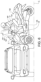
- FIG. 6 is a schematic view if a frontal crash between a car and a powered saddle-ride type vehicle.
- FIG. 7 a discloses one embodiment of a powered saddle-ride type vehicle in a condition when a first design of the airbag has been inflated and deployed.
- FIG. 7 b discloses one embodiment of a powered saddle-ride type vehicle in a condition when a second design of the airbag has been inflated and deployed.
- FIGS. 8 a - 8 c disclose, highly schematically, three different embodiments of airbags with knee-protections.
- the invention refers to an airbag system 1 for a powered saddle-ride type vehicle 100 .
- the term “powered saddle-ride type vehicle” is to be understood as a vehicle where the driver in the ordinary use of the vehicle is seated in a sitting position on a saddle.
- a non-exhaustive list of vehicles of this type includes a motorcycle, a scooter, a moped, a water jet ski or a snow mobile.
- the invention provides an airbag system 1 which is specifically developed for a vehicle 100 of the type where the driver is seated in a non-belted condition, and where the vehicle lacks safety arrangements which are typically integrated in cars, such as deformation zones, a cage structure and numerous airbags.
- the inventive airbag system 1 comprises, in its broadest aspect, an elongated housing 2 which is configured to be fixedly mounted next to a steering column 101 of the vehicle 100 , and more precisely to a leg shield 102 of the steering column 101 of the vehicle 100 .
- the housing 2 may be arranged in level with the driver's knees as seen in the driver's normal driving position.
- the driver's knees are typically substantially in level with the saddle 103 .
- the level of a driver's knees depends on the length of the driver which depends from person to person.
- the term “level” should be understood as an area having a limited vertical extension rather than a horizontal line.
- the elongated housing 2 is configured to be mounted in a substantially horizontal direction, and transverse to a longitudinally extending centreline CL of the vehicle.
- This centreline is often referred to as the Y-axis by the skilled person in the vehicle industry.
- the housing 2 may be arranged symmetrically with the longitudinally extending centreline CL.
- the housing has a thickness that is substantially smaller than its height and longitudinal extension.
- the housing 2 has an elongated shape and comprises a cover 3 configured to face the driver and a bracket 4 forming a rear wall 5 of the housing 2 .
- the cover 3 and the bracket 4 do together define a closed volume that is configured to contain an airbag and an inflator.
- the elongated housing comprises two flanks 16 A and 16 B.
- the bracket 4 which forms the rear wall 5 of the housing 2 comprises a plurality of throughgoing holes 8 configured to allow the housing 2 to be fixedly mounted to the leg shield 102 which as such is directly or indirectly supported by the steering column of the vehicle 100 . Further, the bracket 4 comprises a circumferential rim portion 9 configured to sealingly engage the cover 3 .
- the bracket 4 comprises a central portion 10 configured to support the inflator 7 .
- the inflator 7 is in the disclosed embodiment configured to be fixedly arranged to the bracket 4 by means of four screws or rivets (not illustrated) via a group of mating holes 11 in the inflator 7 and the bracket 4 respectively.
- the central portion 10 comprises a through-going opening 12 configured to receive wiring (not illustrated) required for the operation of the inflator 7 .
- the housing 2 and especially its bracket 4 may have an overall surface extension that corresponds to the surface extension of the leg shield 102 to which it is configured to be fixedly mounted.
- the bracket 4 may accordingly have a substantially flat surface extension or a curved extension.
- the inflator 7 which as such is well known in the art of airbag systems 1 , may comprise a non-disclosed gas generator.
- the inflator 7 is configured to be connected to an ECU (Electrical Control Unit) of the vehicle 100 and to be activated based on an activation signal which is indicating a frontal crash. This may be made by using one or more sensors on the vehicle.
- ECU Electronic Control Unit
- the cover 3 comprises a front wall 13 which in turn comprises a circumferential rim portion 14 configured to sealingly engage the circumferential rim portion 9 of the bracket 4 .
- the interface between the bracket 4 and cover 3 may be provided with a sealing member (not illustrated).
- the cover 3 is configured to be mounted to the bracket 4 to form a closed and sealed housing. This may be made by e.g. screwing, snap-fits, welding, adhesive bonding.
- the closure may be made tamper-proof. It is preferred that the closure is made to resist humidity and rain.
- a central portion 15 of the cover 3 comprises an area having a locally enlarged depth, thereby allowing accommodation of the inflator 7 . It is preferred that the inflator 7 is centrally arranged in the housing 2 . Thus, the inflator 7 is arranged in a central position of the housing 2 where the housing 2 has a locally enlarged depth as compared to the depth of the two opposing flanks 16 A, 16 B of the housing 2 .
- the inflator 7 will be axially aligned with the longitudinally extending centreline CL of the vehicle 100 and the two flanks 16 A, 16 B of the housing 2 will be arranged on opposite sides of the centreline CL. This is best illustrated in FIG. 1 a .
- the locally thicker central portion 15 of the cover 3 , and the thinner flanks 16 A, 16 B will thereby not unduly infringe with the available leg space of the vehicle 100 .
- the cover 3 may comprise an optional padding (not illustrated) on an exterior surface thereof.
- Such optional padding may serve as a knee-protection on the leg shield during ordinary use of the vehicle.
- the cover 3 comprises a split line 17 .
- the split line 17 has, as is best seen in FIG. 3 a , an extension forming an open loop.
- the split line 17 may be formed by a local structurally weaker zone in the material from which the housing 2 is formed.
- the split line 17 may be formed in the inner wall portion of the cover 3 as is disclosed in FIG. 4 a .
- the skilled person realizes that the split line 17 , with remained function, may be formed in the outer wall portion of the cover 3 .
- the housing 2 may instead comprise a split line 17 which has an extension along at least a portion of the circumference of the housing 2 .
- the cover 3 or the housing 2 is configured, upon an activation of the inflator 7 , to rupture long said split line 17 , thereby forming a flap like deflector 18 , see FIG. 4 c .
- the deflector 18 is configured to guide the deployment of the airbag in a direction transverse to the longitudinal extension of the elongated housing 2 . Thereby the airbag will be allowed to be efficiently deployed and fill the available space between the handlebars of the vehicle and the pelvis, abdomen and thorax area of the driver.
- the housing 2 is centrally arranged in view of the longitudinally extending centreline CL, the deployment will be symmetrical in said available space.
- FIG. 5 a a schematic cross section of the housing 2 with an airbag 6 packed therein is disclosed.
- the airbag 6 is disclosed as being packed in the housing 2 in a folded condition.
- the folding is disclosed as being made in a zig-zag fashion.
- the skilled person realizes that the folding may be made in a number of ways with remined function, where the folding pattern is adapted to the overall geometry of the airbag 6 and to its intended deployment.
- FIG. 5 b discloses an alternative embodiment wherein the airbag 6 instead is packed in a rolled condition.
- the airbag 6 is arranged in fluid connection with a gas chamber 19 of the inflator 7 .
- a gas generator 20 which forms part of the inflator 7 will be activated and generate a gas flow which inflates the airbag 6 via the gas chamber 19 .
- the gas enters the airbag 6 via one or more openings 21 in the wall portion of the inflator 7 .
- the split line 17 see FIGS. 4 a - 4 c , will break to thereby form said deflector 18 .
- the airbag 6 has been exemplified as being arranged in the housing 2 in a rolled condition or folded in a zig-zag pattern, the skilled person realizes that other patterns or combinations of different patterns may be used. No matter how the airbag 6 is packed in the housing 2 , it is preferred that the airbag 6 is symmetrically arranged in the housing 2 with a symmetric extension along the opposing flanks 16 A, 16 B on opposite sides of the inflator 7 . Further, it is preferred, no matter pattern, that the airbag 6 is symmetrically inflated and symmetrically deployed on opposite sides of the longitudinal centreline CL of the vehicle.
- the airbag 6 may, as is well known in the art, be made of a flexible fabric material.
- the material may be a textile material such as a woven or non-woven material.
- the material may be plastic or composite material.
- the airbag 6 may be provided with tethers and other types of elements to control the deployment.
- FIG. 6 the operation of the airbag system 1 according to the invention is disclosed.
- the elongated housing 2 containing the inflator 7 and the packed airbag is fixedly mounted to the leg shield 102 of the steering column 101 of the vehicle 100 .
- the housing 2 is illustrated as being arranged in level with the driver's knees as seen in the normal seated position of the driver. It is however to be understood that the housing 2 with remained function may be arranged in other vertical positions in as seen in the area between the handlebars 104 of the vehicle and a foot support 105 of the vehicle.
- the elongated housing 2 is mounted to extend in the horizontal direction and transverse to the longitudinally extending centreline CL of the vehicle 100 .
- the elongated housing 2 is preferably also arranged symmetrically with the longitudinally extending centreline CL of the vehicle 100 .
- the inflator 7 is arranged in communication with the ECU (not illustrated) of the vehicle in a manner which is well known the skilled person.
- an activation signal will be communicated to the inflator 7 which activates the gas generator 20 .
- the gas generator 20 generates a gas flow which inflates the airbag 6 .
- the airbag 6 will inflate and deploy symmetrically on opposite sides of the longitudinally extending centreline CL of the vehicle to thereby fill an available space between the handlebars 104 of the vehicle and the pelvis, abdomen, thorax and head area of the driver.
- the airbag system 1 By arranging the housing 2 on the leg shield 102 of the vehicle 100 , the airbag system 1 will be arranged in an area where it is not in conflict with the otherwise strictly limited dashboard area that is available on this type of vehicles 100 . Further, by packing the airbag 6 in an elongated housing 2 , the thickness of the housing 2 , and especially its opposing flanks 16 A, 16 B may be substantially reduced which is of importance since the available space between the saddle 103 and the leg shield 102 is limited in order of not unduly restricting the leg space for the driver. The latter is of importance for the overall driver's comfort.
- the airbag 6 may have different configurations in its deployed condition in order of providing a coupling of the driver which prevents the driver from tipping over in the event of a frontal crash.
- the airbag 6 may upon an activation thereof be configured to be inflated and deployed to form an inflated body having a lower portion LP, a middle portion MP and an optional upper portion UP, where the middle portion MP has a larger partial volume than the lower portion LP and the optional upper portion UP respectively.
- the lower portion LP of the airbag 6 will thereby in the inflated and deployed condition be received in a position between the drivers' knees/thighs while the middle portion MP of the airbag 6 will abut the driver's pelvis/abdomen/thorax area.
- the airbag 6 also comprises an upper portion UP, as is disclosed in FIGS. 6 and 7 a , this will be arranged in the chest/facial area between the driver's arms, i.e. in the head area.
- the opposite side of the airbag 6 facing away from the driver will in the inflated and deployed condition abut the handlebars 104 and the steering column 101 and thereby prevent the airbag 6 , and hence also the driver's body from tipping forward.
- the airbag 6 will absorb energy in the pelvis/abdomen/thorax area. The loads to the femur and pelvis can thereby be reduced and the driver's upper body is prevented from hitting the obstacle.
- the upper portion UP may, as seen in the inflated and deployed condition of the airbag 6 , have a width W 1 that is smaller than the width of the middle portion W 2 .
- the upper portion UP will thereby be enabled to be better accommodated in the interspace between the driver's arms which during driving are extending in the forward direction to hold the handlebars 104 .
- the lower portion LP has a width W 3 that smaller than the width W 2 of the middle portion MP.
- the lower portion LP may in an inflated and deployed condition of the airbag have a width as seen along the longitudinal direction of the housing which is smaller than the distance between the drivers' knees as seen in a normal, seated driving position.
- FIG. 7 b discloses an alternative embodiment of the inflated and deployed airbag 6 which comprises a lower portion LP and a middle portion MP.
- the airbag 6 do not have the upper portion disclosed in FIG. 7 a .
- the lower portion LP of the airbag 6 will in the inflated and deployed condition be received in a position between the drivers' knees/thighs while the middle portion MP of the airbag 6 will abut the driver's pelvis/abdomen/thorax area. No dedicated coupling of the drivers' head/facial area will be provided for by this airbag design.
- the opposite side of the airbag 6 facing away from the driver will in the inflated and deployed condition abut the handlebars 104 and the steering column 101 and thereby prevent the airbag 6 , and hence also the driver's body from tipping forward. Also, an early coupling with the driver's femur/pelvis area will be enabled. Further, the airbag 6 will absorb energy in the pelvis/abdomen/thorax area. The loads to the femur and pelvis can thereby be reduced and the driver's upper body is prevented from hitting the obstacle.
- the lower portion LP of the airbag 6 may in an inflated and deployed condition of the airbag 6 have a width W 3 as seen along the longitudinal direction of the housing 2 which is smaller than the distance between the drivers' knees as seen in a normal driving position.
- the middle portion MP may in the inflated and deployed condition of the airbag 6 have a width W 2 as seen along the longitudinal direction of the housing 2 which is smaller than the distance between the handlebars 104 of the vehicle 100 but smaller than the width W 3 of the lower portion LP.
- the driver of this type of vehicles will, as long as the grip of the handlebars 104 is remained, have her arms projecting in the forward direction and also often with her body slightly leaning forward.
- the airbag 6 will better fill the volume between the driver's arms and chest and further restrict the forward tipping of the driver's body in the event of a forward crash.
- the middle portion MP may, as seen in the inflated and deployed condition of the airbag 6 , be configured to abut the pelvis, abdomen and thorax area of the driver. It is preferred that the middle portion MP has a width W 2 that allows the pelvis, abdomen and thorax area to be moved in a sideward direction in view of the longitudinal centreline during a crash without losing contact with the intended abutment surface of the airbag 6 . Thereby the airbag system will be highly efficient also in the event of non-strict frontal crashes.
- the middle portion MP may as seen in the inflated and deployed condition of the airbag 6 have a substantially flat surface portion MPS, see FIGS. 7 a and 7 b , configured to abut the pelvis, abdomen and thorax area of the driver. Thereby, the risk of the driver sliding off in the sideward direction will be substantially reduced as compared to a surface portion having a convex curvature.
- the lower portion LP comprises knee-protecting portions 61 .
- the knee-protecting portions 61 are formed as projections that are configured to be deployed in a sideward direction, i.e. transverse to the longitudinal centreline of the vehicle.
- the knee protections 61 are configured to be deployed substantially in level with the knees of the driver as seen in the normally seated position. Thereby, an early coupling with the driver's femur/pelvis area will be further enabled and the loads to the femur and pelvis can thereby be reduced.
- the middle portions MP are like in the previous embodiments configured to abut the pelvis/abdomen/thorax area, and the upper portions UP configured to abut the head/facial area.
- FIG. 8 b differs from the embodiments of FIGS. 8 a and 8 c in that it further comprises shoulder-protecting portions 62 in the upper portion UP thereof.
- the shoulder-protecting portions 62 are formed as projections that are configured to be deployed in a sideward direction, i.e. transverse to the longitudinal centreline of the vehicle.
- the shoulder protections 62 are configured to be deployed in level with the head/facial area and/or in the chest/shoulder area of the driver as seen in the normally seated position.
- FIG. 8 c differs from the embodiments of FIGS. 8 a and 8 b in that the upper portion UP has been omitted.
- An airbag 6 or the type having projections extending in the sideward direction may advantageously be configured to be arranged in the housing 2 in combined rolled and folded condition.
- the material of the airbag 6 may in said middle portion which is configured to abut the abdomen and thorax area of the driver in the deployed condition, be configured to be stretched during the deployment.
- the stretching will add an overall stiffness to the middle portion. This may be provided for by using different material types/properties in local surface areas of the airbag 6 .
- the padding may at least partially be formed by the packed airbag 6 . This may be allowed by providing the cover 3 and/or housing 2 with different strength properties as seen across its surface extension.
Landscapes
- Engineering & Computer Science (AREA)
- Mechanical Engineering (AREA)
- Air Bags (AREA)
Applications Claiming Priority (4)
| Application Number | Priority Date | Filing Date | Title |
|---|---|---|---|
| EP21195576.0A EP4147957B1 (de) | 2021-09-08 | 2021-09-08 | Airbagsystem für ein angetriebenes sattelfahrzeug und mit solch einem system ausgestattetes sattelfahrzeug |
| EP21195576.0 | 2021-09-08 | ||
| EP21195576 | 2021-09-08 | ||
| PCT/EP2022/074698 WO2023036761A1 (en) | 2021-09-08 | 2022-09-06 | Airbag system for a powered saddle-ride type vehicle and a powered saddle-ride type vehicle provided with such system |
Publications (2)
| Publication Number | Publication Date |
|---|---|
| US20240383557A1 US20240383557A1 (en) | 2024-11-21 |
| US12351265B2 true US12351265B2 (en) | 2025-07-08 |
Family
ID=77666402
Family Applications (1)
| Application Number | Title | Priority Date | Filing Date |
|---|---|---|---|
| US18/686,914 Active US12351265B2 (en) | 2021-09-08 | 2022-09-06 | Airbag system for a powered saddle-ride type vehicle and a powered saddle-ride type vehicle provided with such system |
Country Status (6)
| Country | Link |
|---|---|
| US (1) | US12351265B2 (de) |
| EP (1) | EP4147957B1 (de) |
| JP (1) | JP2024530800A (de) |
| CN (1) | CN117916146A (de) |
| ES (1) | ES2986454T3 (de) |
| WO (1) | WO2023036761A1 (de) |
Families Citing this family (1)
| Publication number | Priority date | Publication date | Assignee | Title |
|---|---|---|---|---|
| DE102023126790B4 (de) * | 2023-10-02 | 2026-03-26 | Autoliv Development Ab | Rollerartiges Fahrzeug und Schutzvorrichtung |
Citations (12)
| Publication number | Priority date | Publication date | Assignee | Title |
|---|---|---|---|---|
| FR2486483A1 (fr) * | 1980-07-14 | 1982-01-15 | Haggkvist Bjorn | Dispositif de protection pour les motocyclettes |
| US5096221A (en) * | 1991-02-21 | 1992-03-17 | Davidson Textron Inc. | Air bag door with plural substrates |
| DE4127632C1 (en) * | 1991-08-21 | 1993-02-04 | Bayerische Motoren Werke Ag, 8000 Muenchen, De | Impact restraint pad for motorcyclist - has housing for folded impact bag which restrains riders head and torso |
| US5354094A (en) * | 1990-11-27 | 1994-10-11 | Nissan Motor Co., Ltd. | Air-bag arrangement |
| US5531469A (en) * | 1993-06-18 | 1996-07-02 | Bridgestone Corporation | Air bag housing pad cover and production thereof |
| US5967545A (en) * | 1996-06-11 | 1999-10-19 | Honda Giken Kogyo Kabushiki Kaisha | Device for regulating the pressure of an air bag for a two-wheeled motor vehicle |
| JP2003011871A (ja) | 2001-06-27 | 2003-01-15 | Toyoda Gosei Co Ltd | 鞍乗型車両用エアバッグ装置 |
| EP1375323A2 (de) | 2002-06-27 | 2004-01-02 | Takata Corporation | Airbagvorrichtung, Motorrad mit Airbagvorrichtung, und Herstellungsverfahren für Airbagvorrichtung |
| US20040256848A1 (en) | 2003-06-19 | 2004-12-23 | Takata Corporation | Airbag apparatus, motorcycle equipped with airbag apparatus and manufacturing method of airbag apparatus |
| US20050040628A1 (en) | 2003-08-22 | 2005-02-24 | Takata Corporation | Airbag apparatus, motorbike with airbag apparatus |
| US20060056943A1 (en) * | 2004-09-10 | 2006-03-16 | Honda Motor Co., Ltd. | Rider restraining device for two wheel vehicle |
| JP2018052285A (ja) | 2016-09-28 | 2018-04-05 | 豊田合成株式会社 | バイク用エアバッグ装置 |
-
2021
- 2021-09-08 EP EP21195576.0A patent/EP4147957B1/de active Active
- 2021-09-08 ES ES21195576T patent/ES2986454T3/es active Active
-
2022
- 2022-09-06 JP JP2024514399A patent/JP2024530800A/ja active Pending
- 2022-09-06 US US18/686,914 patent/US12351265B2/en active Active
- 2022-09-06 WO PCT/EP2022/074698 patent/WO2023036761A1/en not_active Ceased
- 2022-09-06 CN CN202280059280.6A patent/CN117916146A/zh active Pending
Patent Citations (13)
| Publication number | Priority date | Publication date | Assignee | Title |
|---|---|---|---|---|
| FR2486483A1 (fr) * | 1980-07-14 | 1982-01-15 | Haggkvist Bjorn | Dispositif de protection pour les motocyclettes |
| US5354094A (en) * | 1990-11-27 | 1994-10-11 | Nissan Motor Co., Ltd. | Air-bag arrangement |
| US5096221A (en) * | 1991-02-21 | 1992-03-17 | Davidson Textron Inc. | Air bag door with plural substrates |
| DE4127632C1 (en) * | 1991-08-21 | 1993-02-04 | Bayerische Motoren Werke Ag, 8000 Muenchen, De | Impact restraint pad for motorcyclist - has housing for folded impact bag which restrains riders head and torso |
| US5531469A (en) * | 1993-06-18 | 1996-07-02 | Bridgestone Corporation | Air bag housing pad cover and production thereof |
| US5967545A (en) * | 1996-06-11 | 1999-10-19 | Honda Giken Kogyo Kabushiki Kaisha | Device for regulating the pressure of an air bag for a two-wheeled motor vehicle |
| JP2003011871A (ja) | 2001-06-27 | 2003-01-15 | Toyoda Gosei Co Ltd | 鞍乗型車両用エアバッグ装置 |
| EP1375323A2 (de) | 2002-06-27 | 2004-01-02 | Takata Corporation | Airbagvorrichtung, Motorrad mit Airbagvorrichtung, und Herstellungsverfahren für Airbagvorrichtung |
| US20040051281A1 (en) * | 2002-06-27 | 2004-03-18 | Takata Corporation | Airbag apparatus, motorcycle with airbag apparatus, and method of manufacturing airbag apparatus |
| US20040256848A1 (en) | 2003-06-19 | 2004-12-23 | Takata Corporation | Airbag apparatus, motorcycle equipped with airbag apparatus and manufacturing method of airbag apparatus |
| US20050040628A1 (en) | 2003-08-22 | 2005-02-24 | Takata Corporation | Airbag apparatus, motorbike with airbag apparatus |
| US20060056943A1 (en) * | 2004-09-10 | 2006-03-16 | Honda Motor Co., Ltd. | Rider restraining device for two wheel vehicle |
| JP2018052285A (ja) | 2016-09-28 | 2018-04-05 | 豊田合成株式会社 | バイク用エアバッグ装置 |
Non-Patent Citations (2)
| Title |
|---|
| Extended European Search Report for Application No. 21195576.0 dated Feb. 1, 2022, 7 pages. |
| International Search Report and Written Opinion for Application No. PCT/EP2022/074698 dated Nov. 25, 2022, 8 pages. |
Also Published As
| Publication number | Publication date |
|---|---|
| CN117916146A (zh) | 2024-04-19 |
| JP2024530800A (ja) | 2024-08-23 |
| EP4147957A1 (de) | 2023-03-15 |
| EP4147957C0 (de) | 2024-05-22 |
| US20240383557A1 (en) | 2024-11-21 |
| ES2986454T3 (es) | 2024-11-11 |
| EP4147957B1 (de) | 2024-05-22 |
| WO2023036761A1 (en) | 2023-03-16 |
Similar Documents
| Publication | Publication Date | Title |
|---|---|---|
| CN103857564B (zh) | 车辆用膝部安全气囊装置 | |
| US5797620A (en) | Knee guard device | |
| US20200238944A1 (en) | Airbag Assembly for a Vehicle Seat of a Motor Vehicle | |
| US20160144818A1 (en) | Airbag module | |
| JP4552840B2 (ja) | サイドエアバッグ装置 | |
| US20060028009A1 (en) | Airbag device | |
| US9180832B2 (en) | Air bag for vehicles | |
| US7946619B2 (en) | Airbag | |
| US11724661B2 (en) | Seat airbag device for vehicle | |
| US7588264B2 (en) | Airbag system and motorcycle with airbag system | |
| EP1813517B1 (de) | Airbagsystem für ein Motorrad und Motorrad | |
| US7566070B2 (en) | Airbag system and motorcycle with airbag system | |
| US20080224456A1 (en) | Motorcycle airbag module | |
| JP4181843B2 (ja) | エアバッグ装置、エアバッグ装置付オートバイおよびエアバッグ装置の製造方法 | |
| US20240383557A1 (en) | Airbag system for a powered saddle-ride type vehicle and a powered saddle-ride type vehicle provided with such system | |
| US12172596B2 (en) | Air bag device for pedestrian protection and method for producing same | |
| KR20150022257A (ko) | 차량용 에어백 장치 | |
| WO2023100544A1 (ja) | 車両用エアバッグ装置 | |
| JP7763800B2 (ja) | オートバイ用エアバッグ装置 | |
| JP7507740B2 (ja) | オートバイ用エアバッグ装置 | |
| JP7762297B2 (ja) | 車両用エアバッグ装置 | |
| KR100814672B1 (ko) | 사이드에어백 | |
| US20240198950A1 (en) | Central airbag, and vehicle occupant restraint system having a central airbag | |
| JP7494158B2 (ja) | オートバイ用安全装置 | |
| JP5725046B2 (ja) | 膝側面拘束用エアバッグ装置 |
Legal Events
| Date | Code | Title | Description |
|---|---|---|---|
| FEPP | Fee payment procedure |
Free format text: ENTITY STATUS SET TO UNDISCOUNTED (ORIGINAL EVENT CODE: BIG.); ENTITY STATUS OF PATENT OWNER: LARGE ENTITY |
|
| AS | Assignment |
Owner name: PIAGGIO & C. S.P.A., ITALY Free format text: ASSIGNMENT OF ASSIGNORS INTEREST;ASSIGNORS:WESTERGREN, ANDERS;RYDSMO, ERIK;BACKMAN, KENNETH;AND OTHERS;SIGNING DATES FROM 20240216 TO 20240220;REEL/FRAME:066630/0166 |
|
| STPP | Information on status: patent application and granting procedure in general |
Free format text: RESPONSE TO NON-FINAL OFFICE ACTION ENTERED AND FORWARDED TO EXAMINER |
|
| STPP | Information on status: patent application and granting procedure in general |
Free format text: EX PARTE QUAYLE ACTION MAILED |
|
| STPP | Information on status: patent application and granting procedure in general |
Free format text: RESPONSE TO EX PARTE QUAYLE ACTION ENTERED AND FORWARDED TO EXAMINER |
|
| AS | Assignment |
Owner name: PIAGGIO & C.S.P.A, ITALY Free format text: ASSIGNMENT OF ASSIGNORS INTEREST;ASSIGNOR:AUTOLIV DEVELOPMENT AB;REEL/FRAME:071275/0358 Effective date: 20250514 |
|
| STCF | Information on status: patent grant |
Free format text: PATENTED CASE |