US12347957B2 - Electrical connector with improved contacts - Google Patents
Electrical connector with improved contacts Download PDFInfo
- Publication number
- US12347957B2 US12347957B2 US17/894,042 US202217894042A US12347957B2 US 12347957 B2 US12347957 B2 US 12347957B2 US 202217894042 A US202217894042 A US 202217894042A US 12347957 B2 US12347957 B2 US 12347957B2
- Authority
- US
- United States
- Prior art keywords
- limb
- base part
- bent
- electrical connector
- limbs
- Prior art date
- Legal status (The legal status is an assumption and is not a legal conclusion. Google has not performed a legal analysis and makes no representation as to the accuracy of the status listed.)
- Active, expires
Links
Images


Classifications
-
- H—ELECTRICITY
- H05—ELECTRIC TECHNIQUES NOT OTHERWISE PROVIDED FOR
- H05K—PRINTED CIRCUITS; CASINGS OR CONSTRUCTIONAL DETAILS OF ELECTRIC APPARATUS; MANUFACTURE OF ASSEMBLAGES OF ELECTRICAL COMPONENTS
- H05K7/00—Constructional details common to different types of electric apparatus
- H05K7/02—Arrangements of circuit components or wiring on supporting structure
- H05K7/10—Plug-in assemblages of components, e.g. IC sockets
- H05K7/1053—Plug-in assemblages of components, e.g. IC sockets having interior leads
- H05K7/1061—Plug-in assemblages of components, e.g. IC sockets having interior leads co-operating by abutting
- H05K7/1069—Plug-in assemblages of components, e.g. IC sockets having interior leads co-operating by abutting with spring contact pieces
-
- H—ELECTRICITY
- H01—ELECTRIC ELEMENTS
- H01R—ELECTRICALLY-CONDUCTIVE CONNECTIONS; STRUCTURAL ASSOCIATIONS OF A PLURALITY OF MUTUALLY-INSULATED ELECTRICAL CONNECTING ELEMENTS; COUPLING DEVICES; CURRENT COLLECTORS
- H01R12/00—Structural associations of a plurality of mutually-insulated electrical connecting elements, specially adapted for printed circuits, e.g. printed circuit boards [PCB], flat or ribbon cables, or like generally planar structures, e.g. terminal strips, terminal blocks; Coupling devices specially adapted for printed circuits, flat or ribbon cables, or like generally planar structures; Terminals specially adapted for contact with, or insertion into, printed circuits, flat or ribbon cables, or like generally planar structures
- H01R12/50—Fixed connections
- H01R12/51—Fixed connections for rigid printed circuits or like structures
- H01R12/55—Fixed connections for rigid printed circuits or like structures characterised by the terminals
- H01R12/57—Fixed connections for rigid printed circuits or like structures characterised by the terminals surface mounting terminals
-
- H—ELECTRICITY
- H01—ELECTRIC ELEMENTS
- H01R—ELECTRICALLY-CONDUCTIVE CONNECTIONS; STRUCTURAL ASSOCIATIONS OF A PLURALITY OF MUTUALLY-INSULATED ELECTRICAL CONNECTING ELEMENTS; COUPLING DEVICES; CURRENT COLLECTORS
- H01R12/00—Structural associations of a plurality of mutually-insulated electrical connecting elements, specially adapted for printed circuits, e.g. printed circuit boards [PCB], flat or ribbon cables, or like generally planar structures, e.g. terminal strips, terminal blocks; Coupling devices specially adapted for printed circuits, flat or ribbon cables, or like generally planar structures; Terminals specially adapted for contact with, or insertion into, printed circuits, flat or ribbon cables, or like generally planar structures
- H01R12/70—Coupling devices
- H01R12/7076—Coupling devices for connection between PCB and component, e.g. display
-
- H—ELECTRICITY
- H01—ELECTRIC ELEMENTS
- H01R—ELECTRICALLY-CONDUCTIVE CONNECTIONS; STRUCTURAL ASSOCIATIONS OF A PLURALITY OF MUTUALLY-INSULATED ELECTRICAL CONNECTING ELEMENTS; COUPLING DEVICES; CURRENT COLLECTORS
- H01R12/00—Structural associations of a plurality of mutually-insulated electrical connecting elements, specially adapted for printed circuits, e.g. printed circuit boards [PCB], flat or ribbon cables, or like generally planar structures, e.g. terminal strips, terminal blocks; Coupling devices specially adapted for printed circuits, flat or ribbon cables, or like generally planar structures; Terminals specially adapted for contact with, or insertion into, printed circuits, flat or ribbon cables, or like generally planar structures
- H01R12/70—Coupling devices
- H01R12/7082—Coupling device supported only by cooperation with PCB
-
- H—ELECTRICITY
- H01—ELECTRIC ELEMENTS
- H01R—ELECTRICALLY-CONDUCTIVE CONNECTIONS; STRUCTURAL ASSOCIATIONS OF A PLURALITY OF MUTUALLY-INSULATED ELECTRICAL CONNECTING ELEMENTS; COUPLING DEVICES; CURRENT COLLECTORS
- H01R13/00—Details of coupling devices of the kinds covered by groups H01R12/70 or H01R24/00 - H01R33/00
- H01R13/02—Contact members
- H01R13/22—Contacts for co-operating by abutting
- H01R13/24—Contacts for co-operating by abutting resilient; resiliently-mounted
- H01R13/2442—Contacts for co-operating by abutting resilient; resiliently-mounted with a single cantilevered beam
-
- H—ELECTRICITY
- H01—ELECTRIC ELEMENTS
- H01R—ELECTRICALLY-CONDUCTIVE CONNECTIONS; STRUCTURAL ASSOCIATIONS OF A PLURALITY OF MUTUALLY-INSULATED ELECTRICAL CONNECTING ELEMENTS; COUPLING DEVICES; CURRENT COLLECTORS
- H01R13/00—Details of coupling devices of the kinds covered by groups H01R12/70 or H01R24/00 - H01R33/00
- H01R13/02—Contact members
- H01R13/22—Contacts for co-operating by abutting
- H01R13/24—Contacts for co-operating by abutting resilient; resiliently-mounted
- H01R13/2464—Contacts for co-operating by abutting resilient; resiliently-mounted characterized by the contact point
- H01R13/2492—Contacts for co-operating by abutting resilient; resiliently-mounted characterized by the contact point multiple contact points
-
- H—ELECTRICITY
- H05—ELECTRIC TECHNIQUES NOT OTHERWISE PROVIDED FOR
- H05K—PRINTED CIRCUITS; CASINGS OR CONSTRUCTIONAL DETAILS OF ELECTRIC APPARATUS; MANUFACTURE OF ASSEMBLAGES OF ELECTRICAL COMPONENTS
- H05K7/00—Constructional details common to different types of electric apparatus
- H05K7/02—Arrangements of circuit components or wiring on supporting structure
- H05K7/10—Plug-in assemblages of components, e.g. IC sockets
-
- H—ELECTRICITY
- H01—ELECTRIC ELEMENTS
- H01R—ELECTRICALLY-CONDUCTIVE CONNECTIONS; STRUCTURAL ASSOCIATIONS OF A PLURALITY OF MUTUALLY-INSULATED ELECTRICAL CONNECTING ELEMENTS; COUPLING DEVICES; CURRENT COLLECTORS
- H01R13/00—Details of coupling devices of the kinds covered by groups H01R12/70 or H01R24/00 - H01R33/00
- H01R13/02—Contact members
- H01R13/22—Contacts for co-operating by abutting
- H01R13/24—Contacts for co-operating by abutting resilient; resiliently-mounted
- H01R13/2435—Contacts for co-operating by abutting resilient; resiliently-mounted with opposite contact points, e.g. C beam
-
- H—ELECTRICITY
- H01—ELECTRIC ELEMENTS
- H01R—ELECTRICALLY-CONDUCTIVE CONNECTIONS; STRUCTURAL ASSOCIATIONS OF A PLURALITY OF MUTUALLY-INSULATED ELECTRICAL CONNECTING ELEMENTS; COUPLING DEVICES; CURRENT COLLECTORS
- H01R13/00—Details of coupling devices of the kinds covered by groups H01R12/70 or H01R24/00 - H01R33/00
- H01R13/02—Contact members
- H01R13/22—Contacts for co-operating by abutting
- H01R13/24—Contacts for co-operating by abutting resilient; resiliently-mounted
- H01R13/2464—Contacts for co-operating by abutting resilient; resiliently-mounted characterized by the contact point
-
- H—ELECTRICITY
- H01—ELECTRIC ELEMENTS
- H01R—ELECTRICALLY-CONDUCTIVE CONNECTIONS; STRUCTURAL ASSOCIATIONS OF A PLURALITY OF MUTUALLY-INSULATED ELECTRICAL CONNECTING ELEMENTS; COUPLING DEVICES; CURRENT COLLECTORS
- H01R43/00—Apparatus or processes specially adapted for manufacturing, assembling, maintaining, or repairing of line connectors or current collectors or for joining electric conductors
- H01R43/16—Apparatus or processes specially adapted for manufacturing, assembling, maintaining, or repairing of line connectors or current collectors or for joining electric conductors for manufacturing contact members, e.g. by punching and by bending
Definitions
- the present invention relates to an electrical connector, especially to a chip socket for receiving a chip module, such as CPU.
- Contacts for electrical connectors have given thickness and are usually made by stamping and forming planar contact stocks.
- Tubular contacts are preferred for increased coupling and decreased impedance in high-frequency applications as well as for better shielding effects.
- An electrical connector comprising: an insulative housing defining an upper face and a lower face and having a plurality of passageways running though the upper and lower face; and a plurality of contacts secured in the plurality of passageways of the insulative housing, each of the plurality of contacts comprising a base part, an upper arm extending from the base part, and a first part and a second part bent from opposite sides of the base part, a first limb bent from the first part and a second limb bent from the second part; wherein the first limb and the second limb are located staggered in an upper and lower direction, thereby the base part, the first and second part and the first and second limbs together form a tubular structure.
- FIG. 1 is a perspective view of an electrical connector of a first embodiment in accordance with the present invention
- FIG. 2 is another perspective view of the electrical connector in FIG. 1 ;
- FIG. 3 is a perspective view of a contact in the electrical connector in FIG. 1 , wherein a strip is connecting with the contacts;
- FIG. 4 is another exploded view of the contact in FIG. 3 ;
- FIG. 5 is another exploded view of the contact in FIG. 3 ;
- FIG. 6 is a front elevational view of the contact in FIG. 3 ;
- FIG. 7 is a side planner view of the contact in FIG. 3 .
- FIG. 10 is another exploded view of the contact in FIG. 9 .
- two first bending portions 281 jointed with the base part 21 and the first part 23 are located at opposite sides of the first limb 25 in the upper and lower direction as viewed from a first direction perpendicular to the base part (as shown in FIG. 6 ), the two second limbs 26 separate from the first part 25 with a gap 291 as viewed from the first direction.
- a second bending portion 282 joined with the base part 21 and the second part 24 are located between the two second limbs 26 in the upper and lower direction as viewed in the first direction, and the first limb 25 separate from the second part 24 with a gap 292 as view from the first direction.
- first bending portion 281 and the second bending portion 282 are visible as viewed from the first direction.
- tools pass through the first gap 291 and the second gap 292 and fitly press against the first and second bending portions 281 , 282 , then the first and second part 23 , 24 can be formed by bending.
- the passageway 11 defines two protruding portions 112 at opposite corners thereof, and the contact 20 is supported by the protruding portions 112 .
- the lower leg 27 extends from the base part 21 and has a soldering plate to be soldered with a solder ball.
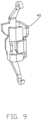
- FIGS. 8 - 10 show that the contact 40 has a lower arm 41 with a contacting portion 411 , and other features are same to the contact 20 .
Landscapes
- Engineering & Computer Science (AREA)
- Microelectronics & Electronic Packaging (AREA)
- Details Of Connecting Devices For Male And Female Coupling (AREA)
- Coupling Device And Connection With Printed Circuit (AREA)
Abstract
Description
Claims (9)
Priority Applications (2)
| Application Number | Priority Date | Filing Date | Title |
|---|---|---|---|
| US17/894,042 US12347957B2 (en) | 2022-08-23 | 2022-08-23 | Electrical connector with improved contacts |
| TW112131049A TW202429772A (en) | 2022-08-23 | 2023-08-18 | Electrical connector |
Applications Claiming Priority (1)
| Application Number | Priority Date | Filing Date | Title |
|---|---|---|---|
| US17/894,042 US12347957B2 (en) | 2022-08-23 | 2022-08-23 | Electrical connector with improved contacts |
Publications (2)
| Publication Number | Publication Date |
|---|---|
| US20240072477A1 US20240072477A1 (en) | 2024-02-29 |
| US12347957B2 true US12347957B2 (en) | 2025-07-01 |
Family
ID=89994385
Family Applications (1)
| Application Number | Title | Priority Date | Filing Date |
|---|---|---|---|
| US17/894,042 Active 2043-09-21 US12347957B2 (en) | 2022-08-23 | 2022-08-23 | Electrical connector with improved contacts |
Country Status (1)
| Country | Link |
|---|---|
| US (1) | US12347957B2 (en) |
Citations (11)
| Publication number | Priority date | Publication date | Assignee | Title |
|---|---|---|---|---|
| US20040259394A1 (en) | 2003-06-05 | 2004-12-23 | Chun-Hsiang Chiang | Conductive terminal and electrical connector applying the conductive terminal |
| US7074055B2 (en) * | 2004-07-23 | 2006-07-11 | Hon Hai Precision Ind. Co., Ltd. | Electrical contact |
| US20090047817A1 (en) * | 2007-08-17 | 2009-02-19 | Hon Hai Precision Ind. Co., Ltd. | Electrical contact having asymmetric dual-contact-engaging-arm |
| US20100297866A1 (en) * | 2009-05-19 | 2010-11-25 | Ted Ju | Electrical connector |
| US20170271801A1 (en) | 2016-03-17 | 2017-09-21 | Foxconn Interconnect Technology Limited | Electrical connector with zero-insertion-force forminals |
| US20190103687A1 (en) * | 2017-09-29 | 2019-04-04 | Intel Corporation | Cpu socket contact for improving bandwidth throughput |
| US20190190207A1 (en) * | 2017-12-19 | 2019-06-20 | Lotes Co., Ltd | Electrical connector |
| US20190334272A1 (en) | 2018-04-27 | 2019-10-31 | Fu Ding Precision Component (Shen Zhen) Co., Ltd. | Electrical contact |
| CN111029819A (en) | 2019-12-25 | 2020-04-17 | 番禺得意精密电子工业有限公司 | Electrical connector |
| US20210203098A1 (en) | 2019-12-26 | 2021-07-01 | Foxconn (Kunshan) Computer Connector Co., Ltd. | Electrical contact |
| CN114188746A (en) | 2020-09-15 | 2022-03-15 | 富士康(昆山)电脑接插件有限公司 | electrical connector |
-
2022
- 2022-08-23 US US17/894,042 patent/US12347957B2/en active Active
Patent Citations (11)
| Publication number | Priority date | Publication date | Assignee | Title |
|---|---|---|---|---|
| US20040259394A1 (en) | 2003-06-05 | 2004-12-23 | Chun-Hsiang Chiang | Conductive terminal and electrical connector applying the conductive terminal |
| US7074055B2 (en) * | 2004-07-23 | 2006-07-11 | Hon Hai Precision Ind. Co., Ltd. | Electrical contact |
| US20090047817A1 (en) * | 2007-08-17 | 2009-02-19 | Hon Hai Precision Ind. Co., Ltd. | Electrical contact having asymmetric dual-contact-engaging-arm |
| US20100297866A1 (en) * | 2009-05-19 | 2010-11-25 | Ted Ju | Electrical connector |
| US20170271801A1 (en) | 2016-03-17 | 2017-09-21 | Foxconn Interconnect Technology Limited | Electrical connector with zero-insertion-force forminals |
| US20190103687A1 (en) * | 2017-09-29 | 2019-04-04 | Intel Corporation | Cpu socket contact for improving bandwidth throughput |
| US20190190207A1 (en) * | 2017-12-19 | 2019-06-20 | Lotes Co., Ltd | Electrical connector |
| US20190334272A1 (en) | 2018-04-27 | 2019-10-31 | Fu Ding Precision Component (Shen Zhen) Co., Ltd. | Electrical contact |
| CN111029819A (en) | 2019-12-25 | 2020-04-17 | 番禺得意精密电子工业有限公司 | Electrical connector |
| US20210203098A1 (en) | 2019-12-26 | 2021-07-01 | Foxconn (Kunshan) Computer Connector Co., Ltd. | Electrical contact |
| CN114188746A (en) | 2020-09-15 | 2022-03-15 | 富士康(昆山)电脑接插件有限公司 | electrical connector |
Also Published As
| Publication number | Publication date |
|---|---|
| US20240072477A1 (en) | 2024-02-29 |
Similar Documents
| Publication | Publication Date | Title |
|---|---|---|
| US8333614B2 (en) | Electrical connector having terminals with increased distances among mounting portions thereof | |
| US10897097B2 (en) | Electrical connector device | |
| US7775805B2 (en) | Electrical terminal | |
| US7559811B1 (en) | Terminal with reduced contact tip | |
| JP4295270B2 (en) | Connector, mating connector and assembly thereof | |
| US10651584B2 (en) | Low profile electrical connector | |
| US7713088B2 (en) | Broadside-coupled signal pair configurations for electrical connectors | |
| US7878818B2 (en) | Electrical socket having contact terminals arranged in fan-out pitch arrangement | |
| US11626678B2 (en) | Connector for high-speed transmission and method for fixing solder to fork portion of connector for high-speed transmission | |
| KR19990045776A (en) | Electrical connector and its manufacturing method | |
| TWM517935U (en) | Contact ribbon for connecting cable to substrate | |
| US20140038465A1 (en) | Shielding socket with two pieces contacts and two pieces housing components | |
| US12347957B2 (en) | Electrical connector with improved contacts | |
| US8932085B2 (en) | Electrical connector with a spacer for retaining contacts thereon | |
| TWI858074B (en) | Electrical connector and manufacturing method thereof | |
| US20090163052A1 (en) | Board to board connector with low board mounting profile | |
| US7004763B2 (en) | Board-to-board electrical connector assembly | |
| US10505299B2 (en) | Electrical connector having an improved metal shell with a soldering portion | |
| US8690585B2 (en) | Electrical connector for low profile application | |
| US8449307B2 (en) | Socket connector having contact with multiple beams jointly grasping ball of IC package | |
| US20140080330A1 (en) | Electrical contact and electrical connector used thereof | |
| JP2006202644A (en) | Shell for electrical connector, electrical connector and manufacturing method thereof | |
| JP2020166970A (en) | Multi-pole coaxial connector | |
| JP7120440B2 (en) | Multi-pole connector set and circuit board connection structure | |
| JP4589777B2 (en) | connector |
Legal Events
| Date | Code | Title | Description |
|---|---|---|---|
| AS | Assignment |
Owner name: FOXCONN INTERCONNECT TECHNOLOGY LIMITED, CAYMAN ISLANDS Free format text: ASSIGNMENT OF ASSIGNORS INTEREST;ASSIGNORS:HSU, SHUO-HSIU;HWANG, TZU-YAO;REEL/FRAME:060875/0708 Effective date: 20220812 Owner name: FOXCONN (KUNSHAN) COMPUTER CONNECTOR CO., LTD., CHINA Free format text: ASSIGNMENT OF ASSIGNORS INTEREST;ASSIGNORS:HSU, SHUO-HSIU;HWANG, TZU-YAO;REEL/FRAME:060875/0708 Effective date: 20220812 |
|
| FEPP | Fee payment procedure |
Free format text: ENTITY STATUS SET TO UNDISCOUNTED (ORIGINAL EVENT CODE: BIG.); ENTITY STATUS OF PATENT OWNER: LARGE ENTITY |
|
| STPP | Information on status: patent application and granting procedure in general |
Free format text: DOCKETED NEW CASE - READY FOR EXAMINATION |
|
| STPP | Information on status: patent application and granting procedure in general |
Free format text: NON FINAL ACTION MAILED |
|
| STPP | Information on status: patent application and granting procedure in general |
Free format text: RESPONSE TO NON-FINAL OFFICE ACTION ENTERED AND FORWARDED TO EXAMINER |
|
| STPP | Information on status: patent application and granting procedure in general |
Free format text: NOTICE OF ALLOWANCE MAILED -- APPLICATION RECEIVED IN OFFICE OF PUBLICATIONS |
|
| STCF | Information on status: patent grant |
Free format text: PATENTED CASE |