US12345909B2 - Templated materials, structures including the materials, and methods of using and forming same - Google Patents
Templated materials, structures including the materials, and methods of using and forming same Download PDFInfo
- Publication number
- US12345909B2 US12345909B2 US17/251,675 US201917251675A US12345909B2 US 12345909 B2 US12345909 B2 US 12345909B2 US 201917251675 A US201917251675 A US 201917251675A US 12345909 B2 US12345909 B2 US 12345909B2
- Authority
- US
- United States
- Prior art keywords
- cholesteric
- reflective material
- reflective
- retarder
- electromagnetic radiation
- Prior art date
- Legal status (The legal status is an assumption and is not a legal conclusion. Google has not performed a legal analysis and makes no representation as to the accuracy of the status listed.)
- Active, expires
Links
Images


Classifications
-
- G—PHYSICS
- G02—OPTICS
- G02B—OPTICAL ELEMENTS, SYSTEMS OR APPARATUS
- G02B5/00—Optical elements other than lenses
- G02B5/30—Polarising elements
- G02B5/3083—Birefringent or phase retarding elements
-
- C—CHEMISTRY; METALLURGY
- C08—ORGANIC MACROMOLECULAR COMPOUNDS; THEIR PREPARATION OR CHEMICAL WORKING-UP; COMPOSITIONS BASED THEREON
- C08L—COMPOSITIONS OF MACROMOLECULAR COMPOUNDS
- C08L1/00—Compositions of cellulose, modified cellulose or cellulose derivatives
- C08L1/02—Cellulose; Modified cellulose
- C08L1/04—Oxycellulose; Hydrocellulose, e.g. microcrystalline cellulose
-
- C—CHEMISTRY; METALLURGY
- C09—DYES; PAINTS; POLISHES; NATURAL RESINS; ADHESIVES; COMPOSITIONS NOT OTHERWISE PROVIDED FOR; APPLICATIONS OF MATERIALS NOT OTHERWISE PROVIDED FOR
- C09K—MATERIALS FOR MISCELLANEOUS APPLICATIONS, NOT PROVIDED FOR ELSEWHERE
- C09K19/00—Liquid crystal materials
- C09K19/52—Liquid crystal materials characterised by components which are not liquid crystals, e.g. additives with special physical aspect: solvents, solid particles
- C09K19/58—Dopants or charge transfer agents
- C09K19/586—Optically active dopants; chiral dopants
-
- G—PHYSICS
- G02—OPTICS
- G02B—OPTICAL ELEMENTS, SYSTEMS OR APPARATUS
- G02B1/00—Optical elements characterised by the material of which they are made; Optical coatings for optical elements
- G02B1/08—Optical elements characterised by the material of which they are made; Optical coatings for optical elements made of polarising materials
-
- G—PHYSICS
- G02—OPTICS
- G02B—OPTICAL ELEMENTS, SYSTEMS OR APPARATUS
- G02B5/00—Optical elements other than lenses
- G02B5/08—Mirrors
- G02B5/0816—Multilayer mirrors, i.e. having two or more reflecting layers
-
- G—PHYSICS
- G02—OPTICS
- G02B—OPTICAL ELEMENTS, SYSTEMS OR APPARATUS
- G02B5/00—Optical elements other than lenses
- G02B5/30—Polarising elements
- G02B5/3008—Polarising elements comprising dielectric particles, e.g. birefringent crystals embedded in a matrix
-
- G—PHYSICS
- G02—OPTICS
- G02B—OPTICAL ELEMENTS, SYSTEMS OR APPARATUS
- G02B5/00—Optical elements other than lenses
- G02B5/30—Polarising elements
- G02B5/3016—Polarising elements involving passive liquid crystal elements
-
- G—PHYSICS
- G02—OPTICS
- G02F—OPTICAL DEVICES OR ARRANGEMENTS FOR THE CONTROL OF LIGHT BY MODIFICATION OF THE OPTICAL PROPERTIES OF THE MEDIA OF THE ELEMENTS INVOLVED THEREIN; NON-LINEAR OPTICS; FREQUENCY-CHANGING OF LIGHT; OPTICAL LOGIC ELEMENTS; OPTICAL ANALOGUE/DIGITAL CONVERTERS
- G02F2201/00—Constructional arrangements not provided for in groups G02F1/00 - G02F7/00
- G02F2201/34—Constructional arrangements not provided for in groups G02F1/00 - G02F7/00 reflector
- G02F2201/343—Constructional arrangements not provided for in groups G02F1/00 - G02F7/00 reflector cholesteric liquid crystal reflector
Definitions
- the present disclosure generally relates to materials that can be templated by one or more of biological material and biologically-derived material, to structures including such materials, and to methods of forming and using same.
- Exemplary materials and structures can be used to reflect and/or retard electromagnetic radiation.
- Photonic crystals enable a host of practical applications such as nonlinear waveguides, advanced anticounterfeiting structures, and low-energy-consuming displays; however, the bulk of these material systems are typically prepared via top-down methods such as deposition of materials, photo- and electron-lithography, and etching. Nanofabrication affords precise control over structures, but is obtained at the cost of detrimentally impacting scalability and throughput, hampering economic feasibility, and ultimately limiting such materials' practical scope. Accordingly, improved materials and structures and methods of forming the materials and structures are desired.
- the present disclosure generally relates to materials that can be templated with one or more of biological material and biologically-derived material, such as cellulose, and to methods of forming and using the materials.
- biological material and biologically-derived material such as cellulose
- exemplary materials and structure described herein can be used for a variety of applications, including reflection and/or retardation of electromagnetic radiation in the visible to near infrared (IR) spectra.
- a cholesteric reflective material is provided.
- the cholesteric reflective material is templated by one or more of biological material and biologically-derived material, such that the cholesteric reflective material comprises a chiral nematic (aka cholesteric) structure.
- the cholesteric reflective material comprises or consists of the one or more of biological material and biologically-derived material.
- the cholesteric reflective material can comprise or consist of other materials, such as silica, organo-silica material, titanium oxide, and one or more polymers, or the like.
- the one or more of biological material and biologically-derived material can include one or more of cellulose nanomaterial, chitin nanomaterial (e.g. chitan nanocrystals) and chitosan nanomaterial (e.g. chitosan nanocrystals).
- the cellulose nanomaterial can include, for example, sulfonated cellulose material.
- the cholesteric reflective material can include one or more of additives to modify material properties.
- the cholesteric reflective material can circularly and/or elliptically polarize visible and near-infrared electromagnetic radiation and/or reflect incident visible and near-infrared electromagnetic radiation.
- the wavelengths of electromagnetic radiation reflected by the cholesteric reflective material can be determined by concentrations of compounds in the composition of the cholesteric reflective material, without changing (e.g., the identity of) the compounds.
- a retarder material is provided.
- the retarder material can be templated by one or more of biological material and biologically-derived material, wherein the retarder material comprises a non-chiral nematic structure.
- the biologically-derived material comprises one or more of cellulose nanomaterial, chitin nanomaterial and chitosan nanomaterial.
- the retarder material can include one or more layers, wherein each layer includes aligned nanomaterial.
- the nanomaterial within a layer and/or within different layers can be sourced from different biological sources, such as plants, animals and microorganisms.
- the nanomaterial can be aligned using, for example, a shear force applied to the material.
- a structure is provided.
- the structure can include reflective material and/or retarder material, such as the reflective material and/or retarder material described herein.
- the structures can include various configurations.
- FIG. 1 illustrates a structure in accordance with exemplary embodiments of the disclosure.
- FIG. 2 illustrates cross-sectional scanning electron micrographs of dried Cellulose nanocrystals (CNC)-based cholesteric-like films confirm effectiveness of static 2000 G magnetic field alignment in promoting macroscopic single-domain configurations.
- FIG. 3 illustrates polarized optical micrographs of the CNC-based retardation plates with the director oriented (a) parallel to the polarizer and (b, c) +45° with respect to the polarizer (b) before and (c) after insertion of a 530 nm retardation plate.
- the CNC director has orientation denoted by the double-headed arrow labeled n.
- FIG. 4 illustrates (a) optical setup used to characterize reflection and CD spectra of both single-layer reflective films and their corresponding sandwich structure.
- P is a linear polarizer
- ⁇ /4 is an achromatic quarter-wave plate
- BS is a beam splitter.
- (b) Optical characterization of a visible-range single reflective film and its corresponding sandwich structure. The reflection spectrum of a single reflective cotton-based CNC-organosilica film with linearly polarized (LP), right-handed circularly and right-handed elliptically polarized (RCP) electromagnetic radiation, and left-handed circularly and left-handed elliptically polarized electromagnetic radiation (LCP) incident electromagnetic radiation.
- LP linearly polarized
- RCP right-handed circularly and right-handed elliptically polarized
- LCP left-handed circularly and left-handed elliptically polarized electromagnetic radiation
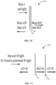
- FIG. 5 illustrates optical characterization of a visibly transparent, single near-IR reflective film and its corresponding sandwich structure.
- FIGS. 6 - 13 illustrate various structures in accordance with various embodiments of the disclosure.
- Various exemplary embodiments of the disclosure relate to materials, structures including the material(s) and to methods of forming and using the material(s).
- the materials and structures described herein allow for a bottom-up manufacturing process, which allows for relatively inexpensive methods to form the desired materials and structures.
- the structures and materials described herein can be used for a variety of applications, including, for example, low-emissivity and solar-gain-regulating films, color and transparent visible-infrared filters, smart fabrics, optically enabled document security features, optical isolators, and other applications where shielding radiative heat while preserving visible-range transparency is desired.
- low-emissivity and solar-gain-regulating films including, for example, low-emissivity and solar-gain-regulating films, color and transparent visible-infrared filters, smart fabrics, optically enabled document security features, optical isolators, and other applications where shielding radiative heat while preserving visible-range transparency is desired.
- the use of inexpensive, abundant biomaterials such as cellulose and the implementation of a bottom-up fabrication approach make these materials a feasible, cost-effective solution that can be readily implemented.
- exemplary embodiments of the disclosure provide cholesteric reflective material templated by one or more of biological material and biologically-derived material.
- the cholesteric reflective material can include periodic liquid crystalline helicoidal arrangements composed of (e.g., cellulose) nanomaterials.
- the term nanomaterial or nanomaterials can refer to, for example, cellulose nanowhiskers, nanocrystalline cellulose (NCC), cellulose nanocrystals (CNCs), nanorods, chitin nanomaterials (e.g. chitin nanocrystals), chitosan nanomaterials (e.g. chitosan nanocrystals), and the like.
- Cellulose nanomaterials can refer to nanomaterials comprising or consisting of cellulose or cellulose-derived material.
- a material can function as a Bragg reflection grating whose center reflection wavelength and reflection bandwidth depend upon the length along the helicoidal axis between consecutive helicoidal twisting periods.
- a length between consecutive helicoidal periods remains constant for a narrow band reflector in the vicinity of the center reflection wavelength.
- the length between consecutive helicoidal periods changes as one follows the helicoidal axis through the thickness of the cholesteric film material for the application of broad band reflector.
- a spacing between consecutive helicoidal twisting periods separated by a 21 rotation, called the pitch is tunable, and thus the resulting reflected wavelength is also tunable from the visible to the near-IR regimes.
- the visible spectrum can be defined to be optical wavelengths between about 400 and about 700 nm.
- the near-IR spectrum can be defined to be radiation wavelengths between about 700 nm and about 2.5 ⁇ m.
- FIG. 1 illustrates a structure 100 in accordance with exemplary embodiments of the disclosure, wherein (a) illustrates a cut-away view of structure 100 and (b) illustrates an exploded view of structure 100 .
- Structure 100 includes a first material 102 , a second material 104 , and a third material 106 .
- structures in accordance with the disclosure can include multiple configurations, wherein the structures include at least one of first material 102 and second material 104 .
- material 102 and/or material 106 is or includes a cholesteric reflective material templated by one or more of biological material and biologically-derived material.
- Material 106 can be the same or similar to material 102 .
- the cholesteric reflective material can have a chiral nematic structure.
- chiral nematic material includes material that adopts a chiral helical structure resembling the liquid crystalline chiral nematic structure.
- the cholesteric reflective material can include or consist of the one or more of biological material and biologically-derived material.
- the cholesteric reflective material can include or consist of cellulose nanomaterial, chitin nanomaterial (e.g., chitin nanocrystals) and chitosan nanomaterials (e.g. chitosan nanocrystals).
- the cellulose nanomaterial can include sulfonated cellulose material.
- the cellulose can be derived from, for example, animals, such as tunicates, microorganisms, such as bacteria (e.g., one or more of Acetobacter hansenil, Acetobacter xylinum ) and/or plants, such as cotton.
- the cholesteric reflective material can be or include one or more of silica, organo-silica material, titanium oxide, and one or more polymers.
- Exemplary polymers include polycondensates of formaldehyde and urea, polycondensate of formaldehyde and melamine, polycondensate of formaldehyde and phenol, poly(ethylene glycol), and chain-wise polymers such as poly(ethylene glycol) diacrylate, poly(acrylic amide), and the like.
- the materials can be templated by the one or more of biological material and biologically-derived material, and the one or more of biological material and biologically-derived material can be removed by dissolution or etching—e.g., using techniques described below.
- material 102 can circularly and/or elliptically polarize (e.g., right-handed) visible and near-infrared electromagnetic radiation. Additionally or alternatively, material 102 can reflect electromagnetic radiation, often polarizing this reflected radiation in the process.
- Material 102 can include one or more additives to modify material properties.
- additives can include softeners or the like, such as plasticizers, such as glucose, fructose, pullulan or other small carbohydrates or small polymeric or oligomeric compounds such as polyethylene glycol and their derivatives, or stiffeners or the likes, such as embedded (e.g., nano) inclusions to enhance mechanical stiffness, such as titanium oxide (TiO 2 ).
- material 102 can reflect electromagnetic radiations and the wavelength of electromagnetic radiation reflected by material 102 can be determined by concentrations of compounds in the composition of the cholesteric reflective material, without changing the compounds—e.g., without changing the chemical makeup of the material or compounds.
- Tunable reflection within the visible and near-IR regimes with material 102 can be achieved by controlling synthetic and processing conditions.
- sulfuric acid-catalyzed hydrolysis of cellulose preferentially etches amorphous cellulose domains, yielding colloidal chiral nanocellulose (e.g., nanocrystalline spindle-shaped rods).
- colloidal chiral nanocellulose e.g., nanocrystalline spindle-shaped rods.
- Different cellulose sources can vary in their degree of crystallinity and/or size of crystallites, and thus the size and yield of the nanomaterial obtained can depend on their source.
- Colloidal stability of the template material can result from Coulombic repulsion between the negatively charged sulfate ester moieties of the sulfonated material (e.g., sulfonated nanomaterial).
- ⁇ is the wavelength of reflected radiation
- n is the average refractive index of the cholesteric medium (taken to be 1.5 for the nanocellulose-organosilica system)
- p is the pitch of the medium, defined as the distance between two LC building blocks separated by a 2 ⁇ rotation
- ⁇ is the angle of incidence with respect to the helical axis X (normal to the plane of the material in this case).
- cotton nanocellulose material is used in material 102 and material 106 due to its smaller size and thus smaller pitch compared to bacterial-based nanocellulose, blue-shifting their reflection into the visible and near-IR domains.
- Material 104 can include any suitable retarder material.
- the retarder material can be templated by one or more of biological material and biologically-derived material, such that the retarder material can include a non-chiral nematic structure.
- material 104 can include or consist of the one or more of biological material and biologically-derived material.
- material can be templated by the one or more of biological material and biologically-derived material and include or consist of other material, such as or more of silica, organo-silica material, titanium oxide, and one or more polymers.
- Exemplary polymers include polycondensate of formaldehyde and urea, polycondensate of formaldehyde and melamine, polycondensate of formaldehyde and phenol, polyethylene glycol, chain-wise polymers such as poly(ethylene glycol) diacrylate, poly(acrylic amide), and the like.
- retarder material includes such materials, the materials can be templated by the one or more of biological material and biologically-derived material, and the one or more of biological material and biologically-derived material can be removed by dissolution or etching—e.g., using techniques described below.
- the retarder material can be or include commercially-available retarder material.
- This layer-by-layer manufacturing approach allows for preparation of optical retarders spanning the visible and near-IR ranges of wavelengths.
- Unidirectionally aligned, nematic-like organization of nanomaterial e.g., pure bacterial and cotton nanomaterial
- polarized optical and scanning electron microscopies respectively.
- Minimal transmitted intensity between crossed polarizers is observed when the shearing direction is parallel to either polarizer ( FIG. 3 ( a ) ).
- Transmission between crossed polarizers is maximized when the nanomaterial director is oriented 45° with respect to either polarizer, confirming the presence of unidirectionally aligned nanomaterial, with their long axes oriented along the shear direction ( FIG. 3 ( b ) ).
- the aligned nanomaterial features positive birefringence, as evidenced by insertion of a 530 nm retardation plate when the director is oriented +45° with respect to the polarizer, causing the overall system to appear bluish ( FIG. 3 ( c ) illustrated in black and white).
- Scanning electron microscopy of the shear plane confirms both bacterial nanomaterial ( FIG. 3 ( d ) ) and cotton nanomaterial ( FIG. 3 ( e ) ) eachadopt the aligned nematic-like configuration with its director oriented along the shear direction.
- Nematic-like bacterial nanomaterial based wave plates with net birefringence of about ⁇ n 0.0226 and retardation spanning from 48 to 838 nm ( FIG.
- Bacterial nanomaterials are larger and retard radiation more than cotton nanomaterials, enabling coarse and fine adjustments of the wave plate's retardation.
- An average wavelength retardation ⁇ n(d) per unit material thickness d for bacterial nanomaterial is found to be 22.6 nm of retardation per micrometer of material thickness, compared to cotton nanomaterial at 6 nm of retardation per micrometer of material thickness.
- a single- (e.g., left-) handed cholesteric-like material can have a theoretical 50% maximum reflection limit due to selective reflection.
- this limitation is overcome with the inclusion of material 104 .
- structure 100 includes two (e.g., left-handed) cholesteric-like composite material 102 and 106 and retarder material 104 .
- Structure 100 can possess a polarization-independent reflection of incident radiation satisfying the Bragg diffraction condition.
- This three-layered structure can achieve total or near total reflection from solely same-handed (e.g., solely left-handed) material.
- any RCP component of incident electromagnetic radiation is transmitted through material 102 , and is then converted into LCP electromagnetic radiation by the retarder material 104 acting as a half-wave plate.
- This LCP electromagnetic radiation is reflected by the material 106 and is converted back into RCP electromagnetic radiation as it transmits through retarder material 104 again.
- this RCP electromagnetic radiation is transmitted through material 102 .
- all polarizations of electromagnetic radiation are reflected, as depicted in the scheme in FIG. 1 ( b ) .
- the reflective performance of the structure is polarization-independent and shows 2-fold reflection enhancement as compared to a single cholesteric-like material. Because the pitch of the material 102 , 106 and the retardation of the nematic-like material are tunable from the visible to near-IR regimes, it follows that this reflection enhancement is also tunable in those same regimes.
- a multiplicity of repeated nematically aligned films and cholesteric reflective films can be stacked to improve reflection bandwidth and/or reflection intensity.
- a stack can include at least two layers comprising the reflective material 102 / 106 and at least one layer comprising the retarder material and a structure can include one or more stacks.
- a non-nematically ordered, e.g., commercially available optical retarder can be used in place of one or more of the nematic-ordered optical retarder.
- Sandwiching material 104 between material 102 and material 106 can increase reflectivity by as much as 95% compared to a material 102 or 106 , due material 104 polarizations of incident radiation satisfying the Bragg diffraction condition.
- Reflection and CD spectra of material 102 / 106 and their corresponding sandwich structure are recorded following the schematic detailed in FIG. 4 ( a ) .
- Spectroscopic data revealing reflection performance of linearly polarized (LP) radiation show a single cholesteric-like organosilica nanocomposite material reflected only 41.6% of peak radiation (occurring at a wavelength of 558.3 nm), reaching 83.2% of its 50% reflection limit originating from selective reflection due to its left-handed chiral structure ( FIG.
- This near doubling of the effective reflection is explained by the nature of LP radiation, which can be thought of as a superposition of in-phase LCP and RCP components.
- the polarization-dependent reflection of a single left-handed cholesteric-like material contrasts with the reflection of the sandwich structure, where polarization-independent reflection is achieved.
- FIG. 4 ( c ) A peak reflected intensity of 73.9% of incident LP radiation at 537.4 nm by the sandwich structure is recorded ( FIG. 4 ( c ) ), corresponding to a 77.64% increase in LP reflection performance compared to a single reflective material.
- the LP reflective performance of the sandwich structure is similar to its performance when LCP radiation is incident, where a peak reflected intensity of 73.9% of 542.5 nm radiation is captured ( FIG. 4 ( c ) ).
- the sandwich structure reflects all polarizations of electromagnetic radiation equally, within experimental error.
- the 9 nm range of peak reflection of the single-layer material and sandwich structure arises from microstructural defects present within the sample.
- the reflective CD spectrum of each structure reinforces the contrast seen in the polarization-dependent nature of a single cholesteric-like material compared to the sandwich structure ( FIG. 4 ( d ) ), as the polarization-dependent single material shows a nontrivial positive CD signal of 60.2% at 567 nm, indicating LCP radiation interacts much more strongly with a single left-handed material than RCP radiation.
- the CD signal of the sandwich structure confirms its polarization-independent interaction with electromagnetic radiation, as a very different CD response is obtained ( FIG. 4 ( e ) ).
- the CD signal of the sandwich structure has a small peak of 11.0% at 567 nm (5.5 times decreased compared to a single material) and is caused by the 9 nm difference in LCP and RCP reflection peaks. Transmission spectra of single materials and their corresponding sandwich structure are characterized by using an optical setup schematically shown in FIG. 4 ( d ) .
- the corresponding transmission spectra of the single material and sandwich structure show similar transmission of natural light (unpolarized electromagnetic radiation) not satisfying the Bragg condition for both structures, except for the reflection trough at 567 nm ( FIG. 4 ( f ) ), which is found to be 66% lower for the sandwich structure compared to its single material counterpart.
- the polarization-dependent interaction of electromagnetic radiation in a single visibly reflective film and the polarization-independent interaction of electromagnetic radiation of its corresponding visibly reflective sandwich structure were confirmed and visualized via reflective optical microscopy.
- a single reflective film was observed to moderately reflect green LCP electromagnetic radiation, while only marginally reflecting incident green LP electromagnetic radiation.
- RCP radiation is incident upon a single reflective film, about 10% of all electromagnetic radiation across the visible spectrum was reflected, and so the corresponding micrograph was dark gray.
- the sandwich structure reflects electromagnetic radiation with all polarizations of incident radiation equally.
- Visibly transparent, near-IR reflective nanomaterial-organosilica photonic structures were prepared by increasing organosilica loading to red-shift both helicoidal optical components' reflection.
- the polarization-dependent nature of a single material compared to the polarization-independent reflection of its corresponding sandwich structure emulates observations of the visibly reflective photonic nanomaterial (e.g., crystal structures). Their reflection, CD, and transmission spectra are obtained using the optical setup detailed in FIGS. 4 ( a ) and ( d ) , respectively.
- a single reflective film has peak LP reflectivity 40.4% at 915.4 nm
- FIG. 5 ( a ) and comparatively shows a 97.0% increase in reflectivity when LCP radiation is incident, reaching 79.6% reflection at 915.4 nm ( FIG. 5 ( a ) ).
- RCP radiation is incident upon a single reflective film, no reflection peak is observed and an average background reflectivity of 6.4% is captured FIG. 5 ( a ) due to reflection caused by the refractive index contrast at each of the film's optical interfaces with air.
- the IR-reflective sandwich structure's reflection is polarization independent, as a peak reflectivity of 83.6% at 895.6 nm is seen when LCP radiation is incident, comparable to peak reflectivity of 81.9% at the same wavelength when LP radiation is incident and peak reflectivity of 80.3% at 893.3 nm when RCP radiation is incident ( FIG. 5 ( b ) ).
- the CD signal of the sandwich structure (stack) confirms its polarization-independent interaction with electromagnetic radiation, as a weak CD signal is obtained, averaging 2.1% ( FIG. 5 ( c ) ).
- a single reflective film's CD spectrum shows a positive signal peaking at 72.5% at 915.4 nm, revealing its highly polarization-dependent interaction with incident radiation ( FIG.
- FIGS. 6 - 13 illustrate exemplary configurations of structures in accordance with the disclosure.
- FIG. 6 illustrates a structure 600 including a single cholesteric reflective material 102 .
- the cholesteric material is left-handed; however, this is not necessarily the case.
- the cholesteric reflective material could alternatively each be right handed or could be a combination of right handed and left handed material.
- Material 102 can reflect LCP, transmit RCP, and acts as an RCP polarizer and an LCP mirror.
- FIG. 7 illustrates a structure 700 that includes a single optical retarder material 104 , which changes handedness of electromagnetic radiation, RCP to LCP or LCP to RCP.
- FIG. 8 illustrates a stack structure 800 (which can be the same or similar to structure 100 ) that can reflect both LCP and RCP, and that achieves total reflection of targeted wavelength/color).
- FIG. 9 illustrates structures 902 , 904 , and 906 including, multiple stacks 908 , which can provide broadband total reflection.
- Each stack 908 includes two cholesteric reflective materials and a retarder material as described herein.
- FIG. 10 illustrates a structure 1000 including multiple cholesteric reflective films, no optical retarder. In the case where one cholesteric reflective material is right handed and the other cholesteric reflective material is left handed, total reflection of targeted wavelengths can be achieved without use of retarder material.
- FIG. 10 illustrates a structure 1000 including multiple cholesteric reflective films, no optical retarder. In the case where one cholesteric reflective material is right handed and the other cholesteric reflective material is left handed, total reflection of targeted wavelengths can be achieved without use of retarder material.
- FIG. 11 illustrates a structure 1100 that includes 1x optical retarder material and 1x cholesteric reflective material, with electromagnetic radiation incident on cholesteric film first.
- Structure 1100 can convert natural (unpolarized) or linearly polarized electromagnetic radiation into reflected LCP and transmitted LCP (half of incident electromagnetic radiation reflected as LCP, half transmitted as RCP and then immediately converted to LCP via the optical retarder).
- FIG. 12 illustrates a structure 1200 that includes 1x retarder material+1x cholesteric reflective material, with electromagnetic radiation incident on optical retarder film first, which converts incident electromagnetic radiation into reflected RCP and transmitted RCP (half of incident electromagnetic radiation reflected as LCP and then converted to RCP by the optical retarder, half transmitted as RCP).
- FIG. 12 illustrates a structure 1200 that includes 1x retarder material+1x cholesteric reflective material, with electromagnetic radiation incident on optical retarder film first, which converts incident electromagnetic radiation into reflected RCP and transmitted RCP (half of incident electromagnetic radiation reflected as LCP and then converted to RCP
- FIG. 13 illustrates a structure 1300 that includes an inverted sandwich structure, which acts opposite of single cholesteric film in that RCP electromagnetic radiation is reflected and LCP transmitted (acts as an LCP polarizer and RCP mirror).
- Other structures are also included within the scope of this disclosure.
- Visibly and near-IR reflective films made solely from CNCs are prepared as follows: Aqueous CNCs are gently sonicated for 10 minutes in 5-15° C. water. Optionally, plasticizer agents or other additives can be added to the aqueous CNCs to enhance the final reflective solid film's mechanical properties, see plasticizer section below.
- the solution is deposited (‘cast’) on a substrate (e.g., a polystyrene Petri dish) and the water is allowed to natural evaporate (‘cure’) under ambient conditions or under various humidity and temperature conditions (from 0-100% relative humidity, from 5° C.
Landscapes
- Physics & Mathematics (AREA)
- Optics & Photonics (AREA)
- General Physics & Mathematics (AREA)
- Chemical & Material Sciences (AREA)
- Crystallography & Structural Chemistry (AREA)
- Organic Chemistry (AREA)
- Health & Medical Sciences (AREA)
- Polymers & Plastics (AREA)
- Medicinal Chemistry (AREA)
- Chemical Kinetics & Catalysis (AREA)
- Engineering & Computer Science (AREA)
- Materials Engineering (AREA)
- Optical Filters (AREA)
- Compositions Of Macromolecular Compounds (AREA)
Abstract
Description
λ=
where λ is the wavelength of reflected radiation, n is the average refractive index of the cholesteric medium (taken to be 1.5 for the nanocellulose-organosilica system), p is the pitch of the medium, defined as the distance between two LC building blocks separated by a 2π rotation, and θ is the angle of incidence with respect to the helical axis X (normal to the plane of the material in this case). In one example, cotton nanocellulose material is used in
| TABLE 1 | |
| reflective color | |
| near- | ||||
| component | blue | green | red | IR |
| cotton CNC (wt %) | 48.7 | 46.0 | 43.9 | 37.4 |
| organosilica (wt %) | 21.3 | 24.0 | 26.1 | 32.6 |
| PEG-400 (wt %) | 30.0 | 30.0 | 30.0 | 30.0 |
Claims (14)
Priority Applications (1)
| Application Number | Priority Date | Filing Date | Title |
|---|---|---|---|
| US17/251,675 US12345909B2 (en) | 2018-06-13 | 2019-06-13 | Templated materials, structures including the materials, and methods of using and forming same |
Applications Claiming Priority (3)
| Application Number | Priority Date | Filing Date | Title |
|---|---|---|---|
| US201862684683P | 2018-06-13 | 2018-06-13 | |
| US17/251,675 US12345909B2 (en) | 2018-06-13 | 2019-06-13 | Templated materials, structures including the materials, and methods of using and forming same |
| PCT/US2019/037121 WO2019241602A1 (en) | 2018-06-13 | 2019-06-13 | Templated materials, structures including the materials, and methods of using and forming same |
Publications (2)
| Publication Number | Publication Date |
|---|---|
| US20210247557A1 US20210247557A1 (en) | 2021-08-12 |
| US12345909B2 true US12345909B2 (en) | 2025-07-01 |
Family
ID=68843130
Family Applications (1)
| Application Number | Title | Priority Date | Filing Date |
|---|---|---|---|
| US17/251,675 Active 2042-08-01 US12345909B2 (en) | 2018-06-13 | 2019-06-13 | Templated materials, structures including the materials, and methods of using and forming same |
Country Status (2)
| Country | Link |
|---|---|
| US (1) | US12345909B2 (en) |
| WO (1) | WO2019241602A1 (en) |
Citations (4)
| Publication number | Priority date | Publication date | Assignee | Title |
|---|---|---|---|---|
| US20070159671A1 (en) * | 2003-05-16 | 2007-07-12 | Nhk Spring Co., Ltd. | Discrimination medium and discrimination method using the same |
| US20110248214A1 (en) * | 2010-04-09 | 2011-10-13 | Fpinnovations | Inorganic mesoporous materials with chiral nematic structures and preparation method thereof |
| US20140295161A1 (en) * | 2011-03-31 | 2014-10-02 | Fpinnovations | Chiral or achiral, mesoporous carbon |
| US20170097530A1 (en) * | 2015-10-01 | 2017-04-06 | Au Optronics Corporation | Photo-conversion means for liquid crystal displays |
Family Cites Families (2)
| Publication number | Priority date | Publication date | Assignee | Title |
|---|---|---|---|---|
| WO2013049921A1 (en) * | 2011-10-06 | 2013-04-11 | University Of British Columbia | Chiral nematic nanocrystalline metal oxides |
| WO2014153645A1 (en) * | 2013-03-25 | 2014-10-02 | The University Of British Columbia | Polymer materials and composite materials with chiral nematic structures and preparation methods thereof |
-
2019
- 2019-06-13 WO PCT/US2019/037121 patent/WO2019241602A1/en not_active Ceased
- 2019-06-13 US US17/251,675 patent/US12345909B2/en active Active
Patent Citations (4)
| Publication number | Priority date | Publication date | Assignee | Title |
|---|---|---|---|---|
| US20070159671A1 (en) * | 2003-05-16 | 2007-07-12 | Nhk Spring Co., Ltd. | Discrimination medium and discrimination method using the same |
| US20110248214A1 (en) * | 2010-04-09 | 2011-10-13 | Fpinnovations | Inorganic mesoporous materials with chiral nematic structures and preparation method thereof |
| US20140295161A1 (en) * | 2011-03-31 | 2014-10-02 | Fpinnovations | Chiral or achiral, mesoporous carbon |
| US20170097530A1 (en) * | 2015-10-01 | 2017-04-06 | Au Optronics Corporation | Photo-conversion means for liquid crystal displays |
Also Published As
| Publication number | Publication date |
|---|---|
| WO2019241602A1 (en) | 2019-12-19 |
| US20210247557A1 (en) | 2021-08-12 |
Similar Documents
| Publication | Publication Date | Title |
|---|---|---|
| CN104950373B (en) | The manufacturing method of liquid-crystal compounds, optical film and optical film | |
| CN104181727B (en) | Inverse wavelength dispersion retardation film and display device including the same | |
| TWI578031B (en) | A liquid crystal display device and a publishing crystal and a polarizing light source device | |
| JP4681628B2 (en) | Polarizer | |
| CN103026274B (en) | Blooming | |
| CN103282806B (en) | Optical film and manufacturing method thereof, polarizing plate and image display element having said optical film, and patterned alignment layer | |
| JP2001004837A (en) | Phase difference plate and circular polarization plate | |
| JP2004528603A (en) | Optical device | |
| US7473446B2 (en) | Retarder and circular polarizer | |
| JP6098223B2 (en) | Functional film | |
| WO2011048989A1 (en) | Heat-insulating particulate pigment and infrared-reflective coating solution | |
| KR20120107256A (en) | Polarizing plate and liquid crystal display device comprising the same | |
| KR20230151987A (en) | Circular polarizer and image display device using the same | |
| US20250172731A1 (en) | Polarizing plate | |
| US12345909B2 (en) | Templated materials, structures including the materials, and methods of using and forming same | |
| TW201512713A (en) | Polarizing plate manufacturing method | |
| JP4209530B2 (en) | Liquid crystal film and optical element | |
| JP4278451B2 (en) | Retardation plate and circularly polarizing plate | |
| JP2012173452A (en) | Depolarizing element | |
| JP2000284120A (en) | Phase difference plate and circular polarizing plate | |
| KR102126682B1 (en) | Polarizing Element and use thereof | |
| CN116018631B (en) | Circular polarizer, organic electroluminescent display device, display device | |
| CN115840266A (en) | Broadband quarter-wave phase compensation film, calculation method and preparation method | |
| CN206374300U (en) | LCD screen diaphragm | |
| KR100803715B1 (en) | Method for manufacturing broadband reflective polarizer with prism pattern |
Legal Events
| Date | Code | Title | Description |
|---|---|---|---|
| FEPP | Fee payment procedure |
Free format text: ENTITY STATUS SET TO UNDISCOUNTED (ORIGINAL EVENT CODE: BIG.); ENTITY STATUS OF PATENT OWNER: SMALL ENTITY |
|
| FEPP | Fee payment procedure |
Free format text: ENTITY STATUS SET TO SMALL (ORIGINAL EVENT CODE: SMAL); ENTITY STATUS OF PATENT OWNER: SMALL ENTITY |
|
| AS | Assignment |
Owner name: U.S. DEPARTMENT OF ENERGY, DISTRICT OF COLUMBIA Free format text: CONFIRMATORY LICENSE;ASSIGNOR:UNIVERSITY OF COLORADO;REEL/FRAME:054810/0639 Effective date: 20201217 |
|
| STPP | Information on status: patent application and granting procedure in general |
Free format text: APPLICATION DISPATCHED FROM PREEXAM, NOT YET DOCKETED |
|
| STPP | Information on status: patent application and granting procedure in general |
Free format text: DOCKETED NEW CASE - READY FOR EXAMINATION |
|
| STPP | Information on status: patent application and granting procedure in general |
Free format text: NON FINAL ACTION MAILED |
|
| STPP | Information on status: patent application and granting procedure in general |
Free format text: RESPONSE TO NON-FINAL OFFICE ACTION ENTERED AND FORWARDED TO EXAMINER |
|
| STPP | Information on status: patent application and granting procedure in general |
Free format text: NOTICE OF ALLOWANCE MAILED -- APPLICATION RECEIVED IN OFFICE OF PUBLICATIONS |
|
| AS | Assignment |
Owner name: THE REGENTS OF THE UNIVERSITY OF COLORADO, A BODY CORPORATE, COLORADO Free format text: ASSIGNMENT OF ASSIGNORS INTEREST;ASSIGNORS:SMALYUKH, IVAN I.;HESS, ANDREW JOHNSTON;LIU, QINGKUN;AND OTHERS;SIGNING DATES FROM 20190715 TO 20190718;REEL/FRAME:070514/0694 |
|
| STCF | Information on status: patent grant |
Free format text: PATENTED CASE |