US12345285B2 - Clam shell insert utility - Google Patents
Clam shell insert utility Download PDFInfo
- Publication number
- US12345285B2 US12345285B2 US18/140,242 US202318140242A US12345285B2 US 12345285 B2 US12345285 B2 US 12345285B2 US 202318140242 A US202318140242 A US 202318140242A US 12345285 B2 US12345285 B2 US 12345285B2
- Authority
- US
- United States
- Prior art keywords
- nut
- housing
- faces
- opening
- cavity
- Prior art date
- Legal status (The legal status is an assumption and is not a legal conclusion. Google has not performed a legal analysis and makes no representation as to the accuracy of the status listed.)
- Active
Links
Images


Classifications
-
- F—MECHANICAL ENGINEERING; LIGHTING; HEATING; WEAPONS; BLASTING
- F16—ENGINEERING ELEMENTS AND UNITS; GENERAL MEASURES FOR PRODUCING AND MAINTAINING EFFECTIVE FUNCTIONING OF MACHINES OR INSTALLATIONS; THERMAL INSULATION IN GENERAL
- F16B—DEVICES FOR FASTENING OR SECURING CONSTRUCTIONAL ELEMENTS OR MACHINE PARTS TOGETHER, e.g. NAILS, BOLTS, CIRCLIPS, CLAMPS, CLIPS OR WEDGES; JOINTS OR JOINTING
- F16B37/00—Nuts or like thread-engaging members
- F16B37/04—Devices for fastening nuts to surfaces, e.g. sheets, plates
- F16B37/044—Nut cages
-
- F—MECHANICAL ENGINEERING; LIGHTING; HEATING; WEAPONS; BLASTING
- F16—ENGINEERING ELEMENTS AND UNITS; GENERAL MEASURES FOR PRODUCING AND MAINTAINING EFFECTIVE FUNCTIONING OF MACHINES OR INSTALLATIONS; THERMAL INSULATION IN GENERAL
- F16B—DEVICES FOR FASTENING OR SECURING CONSTRUCTIONAL ELEMENTS OR MACHINE PARTS TOGETHER, e.g. NAILS, BOLTS, CIRCLIPS, CLAMPS, CLIPS OR WEDGES; JOINTS OR JOINTING
- F16B5/00—Joining sheets or plates, e.g. panels, to one another or to strips or bars parallel to them
- F16B5/01—Joining sheets or plates, e.g. panels, to one another or to strips or bars parallel to them by means of fastening elements specially adapted for honeycomb panels
-
- F—MECHANICAL ENGINEERING; LIGHTING; HEATING; WEAPONS; BLASTING
- F16—ENGINEERING ELEMENTS AND UNITS; GENERAL MEASURES FOR PRODUCING AND MAINTAINING EFFECTIVE FUNCTIONING OF MACHINES OR INSTALLATIONS; THERMAL INSULATION IN GENERAL
- F16B—DEVICES FOR FASTENING OR SECURING CONSTRUCTIONAL ELEMENTS OR MACHINE PARTS TOGETHER, e.g. NAILS, BOLTS, CIRCLIPS, CLAMPS, CLIPS OR WEDGES; JOINTS OR JOINTING
- F16B37/00—Nuts or like thread-engaging members
- F16B37/04—Devices for fastening nuts to surfaces, e.g. sheets, plates
- F16B37/041—Releasable devices
- F16B37/043—Releasable devices with snap action
-
- F—MECHANICAL ENGINEERING; LIGHTING; HEATING; WEAPONS; BLASTING
- F16—ENGINEERING ELEMENTS AND UNITS; GENERAL MEASURES FOR PRODUCING AND MAINTAINING EFFECTIVE FUNCTIONING OF MACHINES OR INSTALLATIONS; THERMAL INSULATION IN GENERAL
- F16B—DEVICES FOR FASTENING OR SECURING CONSTRUCTIONAL ELEMENTS OR MACHINE PARTS TOGETHER, e.g. NAILS, BOLTS, CIRCLIPS, CLAMPS, CLIPS OR WEDGES; JOINTS OR JOINTING
- F16B37/00—Nuts or like thread-engaging members
- F16B37/04—Devices for fastening nuts to surfaces, e.g. sheets, plates
- F16B37/06—Devices for fastening nuts to surfaces, e.g. sheets, plates by means of welding or riveting
- F16B37/061—Devices for fastening nuts to surfaces, e.g. sheets, plates by means of welding or riveting by means of welding
Definitions
- FIG. 3 is a perspective view of another embodiment of the sandwich panel insert of the invention having two halves and the nut in which each half has on abutting surfaces two pegs and two holes for receiving the pegs.
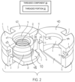
- FIG. 4 shows the embodiment of the floating sandwich panel insert of FIG. 2 completely disassembled.
- FIG. 5 shows the embodiment of the floating sandwich panel insert of FIG. 3 completely disassembled.
- the floating sandwich panel insert 1 of this invention includes a housing formed of two identical halves 2 and 3 which at the top or open end of the insert form an annular lateral distal flange 4 when the two halves are joined or closed on each other like a clamshell.
- the thus formed annular lateral distal flange is provided with slots or holes 5 for the introduction of potting material.
- Each of the halves 2 and 3 when joined forms a central internal bore 6 .
- Each of the halves 2 and 3 has a laterally extending member 7 and 8 when joined forms a tight closed end of the bore 6 .
- Members 7 and 8 are integrally formed with and are part of halves 2 and 3 , respectively.
- each of the halves 2 and 3 have abutting surfaces or faces 9 and 10 in the embodiment of FIGS. 2 and 4 . Faces or abutting surfaces 11 and 12 are shown in the embodiment of FIGS. 3 and 5 . The faces are at the side of the half bores 13 and 14 . In the embodiment of FIGS. 2 and 4 each of the halves' faces has a single laterally projecting peg 15 and a single hole 16 . In the embodiment of FIGS. 2 and 4 , the faces abut when the halves 2 and 3 are joined by the engagement of the peg 15 on one of the halves with the hole 16 on the other half to form the closed insert housing.
- the faces provide abutting surfaces whereby when said halves are joined the peg or pegs are received in the hole or holes by a snap fit.
- the two halves 2 and 3 that comprise the housing are identical and are designed to press fit together, they can be easily assembled using automated equipment.
- the inserts of this invention are stronger than prior inserts (in shear, tensile and/or torque testing), as the weakest member of prior inserts consisted of the cap.
- the present invention eliminates the cap element and allows the strength to be increased by designing the part to allow maximum material in the critical areas of the housing.
- the two identical halves 2 and 3 of the clam shell-like housing are made of a thermoplastic polymeric material.
- the abutting faces 9 with 10 and 11 with 12 are fused or welded to each other by the application of sonic energy which melts and fuses the polymeric material forming the housing.
- the post-assembly welding operation can be automated. Energy directors can be added to half of the abutting surfaces or faces (resulting in the entire abutting surfaces having said energy directors when the two halves are pressed together) to aid in the effectivity of the sonic welding operation, and adding to the strength of the resultant insert assembly.
- the nut 19 is received in the bore 6 of the housing and configured to float therein, and has a truncated flange 20 and a hollow shaft 21 extending from the truncated flange 20 .
- the hollow shaft 21 includes a surface 48 and has internal female threads 22 adapted to receive a threaded portion 32 of a male threaded screw 30 .
- the surface 48 faces toward the inner surfaces 42 , 43 when the two halves 2 and 3 are joined around the nut 19 in the bore 6 . When the threaded portion 32 of the male threaded screw 30 and the internal female threads 22 are sufficiently engaged, the surface 48 and the inner surfaces 42 , 43 apply opposing forces to one another.
- the truncated flange 20 is received in recessed portions of each of the halves 2 and 3 at the closed distal end of bore 6 which prevents the-rotation of the nut within the bore.
- FIGS. 2 and 3 show the nut 19 positioned relative to the half 3 such that one side of the truncated flange 20 is disposed within the recessed portion of the half 3 .
- the recessed portions include the inner surfaces 44 and 45 , respectively ( FIGS. 4 and 5 ).
- the truncated flange 20 includes a surface 50 that faces toward the inner surfaces 44 , 45 when the two halves 2 and 3 are joined around the nut 19 in the bore 6 . When the threaded portion 32 of the male threaded screw 30 and the internal female threads 22 are sufficiently engaged, the surface 50 and the inner surfaces 44 , 45 apply opposing forces to one another.
Landscapes
- Engineering & Computer Science (AREA)
- General Engineering & Computer Science (AREA)
- Mechanical Engineering (AREA)
- Connection Of Plates (AREA)
Abstract
Description
Claims (20)
Priority Applications (1)
| Application Number | Priority Date | Filing Date | Title |
|---|---|---|---|
| US18/140,242 US12345285B2 (en) | 2020-05-13 | 2023-04-27 | Clam shell insert utility |
Applications Claiming Priority (2)
| Application Number | Priority Date | Filing Date | Title |
|---|---|---|---|
| US15/929,617 US11644058B2 (en) | 2020-05-13 | 2020-05-13 | Clam shell insert utility |
| US18/140,242 US12345285B2 (en) | 2020-05-13 | 2023-04-27 | Clam shell insert utility |
Related Parent Applications (1)
| Application Number | Title | Priority Date | Filing Date |
|---|---|---|---|
| US15/929,617 Continuation US11644058B2 (en) | 2020-05-13 | 2020-05-13 | Clam shell insert utility |
Publications (2)
| Publication Number | Publication Date |
|---|---|
| US20230407902A1 US20230407902A1 (en) | 2023-12-21 |
| US12345285B2 true US12345285B2 (en) | 2025-07-01 |
Family
ID=78513209
Family Applications (2)
| Application Number | Title | Priority Date | Filing Date |
|---|---|---|---|
| US15/929,617 Active 2041-04-20 US11644058B2 (en) | 2020-05-13 | 2020-05-13 | Clam shell insert utility |
| US18/140,242 Active US12345285B2 (en) | 2020-05-13 | 2023-04-27 | Clam shell insert utility |
Family Applications Before (1)
| Application Number | Title | Priority Date | Filing Date |
|---|---|---|---|
| US15/929,617 Active 2041-04-20 US11644058B2 (en) | 2020-05-13 | 2020-05-13 | Clam shell insert utility |
Country Status (1)
| Country | Link |
|---|---|
| US (2) | US11644058B2 (en) |
Families Citing this family (1)
| Publication number | Priority date | Publication date | Assignee | Title |
|---|---|---|---|---|
| DE102020117921A1 (en) * | 2020-07-07 | 2022-01-13 | Böllhoff Verbindungstechnik GmbH | Multi-piece socket-type glue-in holder |
Citations (96)
| Publication number | Priority date | Publication date | Assignee | Title |
|---|---|---|---|---|
| US2235078A (en) | 1939-01-19 | 1941-03-18 | Gothaer Waggonfabrik Ag | Nut and screw fastening |
| US2764886A (en) | 1951-04-10 | 1956-10-02 | Robertson Co H H | Identification device for the wiring cells of a floor |
| US3018565A (en) | 1952-11-25 | 1962-01-30 | Cel Elevator Company Inc | Radar sweep simulator |
| US3213914A (en) | 1961-11-06 | 1965-10-26 | Illinois Tool Works | Self-piercing nut with attaching groove |
| US3313078A (en) | 1964-03-30 | 1967-04-11 | Frederick W Rohe | Molded-in insert with floating nut |
| US3339609A (en) | 1965-08-02 | 1967-09-05 | Delron Company Inc | Floating nut insert |
| US3493025A (en) | 1968-04-01 | 1970-02-03 | Youngstown Sheet And Tube Co | Attachment device for apertured structural members |
| US3504723A (en) | 1968-05-27 | 1970-04-07 | Delron Fastener Division Rex C | Floating nut insert |
| US3621557A (en) | 1969-06-06 | 1971-11-23 | Rex Chainbelt Inc | Insert for sandwich panels and method of installation |
| US3646982A (en) | 1969-09-12 | 1972-03-07 | Rex Chainbelt Inc | Encapsulated floating and nonfloating fasteners |
| US3646981A (en) | 1970-06-02 | 1972-03-07 | Amerace Esna Corp | Insert for sandwich panels |
| US3662805A (en) | 1970-05-19 | 1972-05-16 | Illinois Tool Works | Panel insert device |
| US3695324A (en) | 1970-01-09 | 1972-10-03 | Deutsch Fastener Corp | Floating nut assembly |
| US3964531A (en) | 1972-02-04 | 1976-06-22 | Dzus Fastener Co., Inc. | Panel insert |
| US4121963A (en) | 1972-06-15 | 1978-10-24 | Dunlop Limited | Bonding polyamide plastics to rubber compositions |
| US4185438A (en) | 1977-10-08 | 1980-01-29 | Artur Fischer | Element for and a method of mounting an object to a support structure |
| US4227561A (en) | 1978-05-05 | 1980-10-14 | Deutsch Fastener Corp. | Sealed fastener |
| US4341053A (en) | 1979-03-21 | 1982-07-27 | Messerschmitt-Boelkow-Blohm Gesellschaft Mit Beschraenkter Haftung | Built-in connector element for sandwich type compound panels |
| US4417028A (en) | 1981-05-11 | 1983-11-22 | Loctite Corporation | Preapplied plastic film adhesive composition |
| US4428705A (en) | 1980-11-11 | 1984-01-31 | Messerschmitt-Boelkow-Blohm Gesellschaft Mit Beschraenkter Haftung | Spreading dowel for securing an insert in a panel with the aid of the dowel |
| US4509308A (en) | 1982-04-08 | 1985-04-09 | Messerschmitt-Boelkow-Blohm Gmbh | Mounting assembly and method for installing dowels in compound panels |
| USD278594S (en) | 1982-07-30 | 1985-04-30 | Lye Howard D | Ratchet wrench socket unit nut ejector spring retainer |
| US4752171A (en) | 1987-04-16 | 1988-06-21 | Illinois Tool Works, Inc. | Frictionally welded fastening anchor |
| US4812193A (en) | 1986-12-22 | 1989-03-14 | Gauron Richard F | Inset panel fastener and method of using |
| US4817264A (en) | 1987-08-10 | 1989-04-04 | Shur-Lok Corporation | Fastener and assembly process |
| US4846612A (en) | 1987-10-19 | 1989-07-11 | Shur-Lok Corporation | Sandwich panel fastener |
| US4902180A (en) | 1986-12-22 | 1990-02-20 | Gauron Richard F | Inset panel fastener |
| US4973208A (en) | 1989-08-31 | 1990-11-27 | Gauron Richard F | Inset panel fastener with floating member |
| US4993902A (en) | 1990-08-09 | 1991-02-19 | Maclean-Fogg Company | Plastic capped lock nut |
| USD322929S (en) | 1989-06-20 | 1992-01-07 | Skf Specialty Products Ab | Track-guided nut |
| US5082405A (en) | 1989-09-13 | 1992-01-21 | Witten Donald W | Potted insert for honeycomb panels |
| US5092725A (en) | 1989-10-10 | 1992-03-03 | Ford Motor Company | Locking fastener |
| US5240543A (en) | 1990-06-11 | 1993-08-31 | Atr International, Inc. | Apparatus for and method of seating a fastener insert in a honeycomb panel |
| US5302069A (en) | 1992-09-29 | 1994-04-12 | Key Manufacturing Group, Inc. | Stepped, capped wheel nut |
| US5322208A (en) | 1992-07-09 | 1994-06-21 | A. O. Smith Corporation | Method for welding vehicle frame |
| US5378099A (en) | 1993-07-01 | 1995-01-03 | Gauron; Richard F. | Inset panel fastener with shoulder-engaging floating member |
| US5431578A (en) | 1994-03-02 | 1995-07-11 | Abrams Electronics, Inc. | Compression mating electrical connector |
| US5437750A (en) | 1994-04-08 | 1995-08-01 | Fokker Special Products B.V. | Method for securing a thermoplastic insert |
| USD364882S (en) | 1994-06-23 | 1995-12-05 | Junkers John K | Bolt tensioner |
| US5553984A (en) | 1995-01-10 | 1996-09-10 | Smith; Donald E. | Encapsulated nut |
| US5632582A (en) | 1996-07-10 | 1997-05-27 | Gauron; Richard F. | Inset panel fastener with two-part stem |
| US5840149A (en) | 1993-05-21 | 1998-11-24 | Kasai Kogyo Co., Ltd. | Molding method for laminated body using cooling air |
| US5840147A (en) | 1995-06-07 | 1998-11-24 | Edison Welding Institute | Plastic joining method |
| US5947518A (en) | 1996-07-11 | 1999-09-07 | Daimlerchrysler Corporation | Bracket with floating tap plate for connecting vehicle suspension to body |
| US6096253A (en) | 1997-05-22 | 2000-08-01 | Hatsunen Co., Ltd. | Process for producing foundry exothermic body |
| US6146071A (en) | 1999-04-14 | 2000-11-14 | Illinois Tool Works, Inc. | Caged nut assembly |
| US6153035A (en) | 1999-02-12 | 2000-11-28 | The Boeing Company | Method and apparatus for securing a thermoplastic insert within a sandwich panel |
| US6217695B1 (en) | 1996-05-06 | 2001-04-17 | Wmw Systems, Llc | Method and apparatus for radiation heating substrates and applying extruded material |
| US6264412B1 (en) | 1999-01-26 | 2001-07-24 | Sakura Rubber Co., Ltd. | Honeycomb panel fixing device |
| US6273985B1 (en) | 1998-06-26 | 2001-08-14 | Xerox Corporation | Bonding process |
| US6278562B1 (en) | 1997-07-09 | 2001-08-21 | Branson Ultrasonics Corporation | Radiation filter used in welding apparatus |
| US6299596B1 (en) | 1998-03-20 | 2001-10-09 | Schneider (Usa) Inc. | Method of bonding polymers and medical devices comprising materials bonded by said method |
| USD452428S1 (en) | 2000-05-18 | 2001-12-25 | Yugenkaisha Shinjo Seisakusho | Clinch nut |
| USD453000S1 (en) | 2000-05-11 | 2002-01-22 | Yugenkaisha Shinjo Seisakusho | Clinch nut |
| US6350093B1 (en) | 2000-10-02 | 2002-02-26 | Cxt Incorporated | Electrically insulated threaded fastener anchor |
| USD454057S1 (en) | 1999-03-24 | 2002-03-05 | R B & W Manufacturing Llc | Self-piercing clinch nut |
| US6488460B1 (en) | 2000-05-02 | 2002-12-03 | Bell Helicopter Textron Inc. | Composite panel insert with hold out recess feature |
| US20040005205A1 (en) | 2002-04-30 | 2004-01-08 | Yake Donald L. | Cage nut with inverted cage |
| US6692206B1 (en) | 2002-08-16 | 2004-02-17 | Textron Inc. | Split weld cage nut assembly |
| US6733221B2 (en) | 2000-04-27 | 2004-05-11 | Jokab Safety Ab | Insert nut for a screw nut joint |
| US6758645B2 (en) | 2002-02-01 | 2004-07-06 | Illinois Tool Works Inc. | Locking cage fastener |
| US6811363B1 (en) | 2003-02-25 | 2004-11-02 | Dana Corporation | Floating cage nut assembly |
| USD499010S1 (en) | 2003-07-10 | 2004-11-30 | Bosch Rexroth Aktiengesellschaft | Hammer bolt |
| US20050169727A1 (en) | 2004-02-02 | 2005-08-04 | Cosenza Frank J. | Fastener component |
| USD519530S1 (en) | 2004-12-30 | 2006-04-25 | Htc Sweden Ab | Grinding tool |
| USD520859S1 (en) | 2004-09-17 | 2006-05-16 | John D. Brush & Co., Inc. | Knob for a combination lock |
| USD520856S1 (en) | 2004-09-17 | 2006-05-16 | John D. Brush & Co., Inc. | Knob for a combination lock |
| US7124821B2 (en) | 1998-12-22 | 2006-10-24 | Weatherford/Lamb, Inc. | Apparatus and method for expanding a tubular |
| USD534796S1 (en) | 2002-08-02 | 2007-01-09 | Falkenburg Charles W | Bottle coupling device |
| US7192231B2 (en) | 2004-04-05 | 2007-03-20 | Newfrey Llc | Cage nut with non-cross threading angled cage |
| USD545584S1 (en) | 2005-10-21 | 2007-07-03 | David Sutherland, Inc. | Chair |
| USD549091S1 (en) | 2004-12-24 | 2007-08-21 | Mcintyre Dale Michael | Washer |
| USD551269S1 (en) | 2004-08-23 | 2007-09-18 | Irwin Industrial Tool Company | Hole blade |
| USD557132S1 (en) | 2006-06-05 | 2007-12-11 | Shinjo Manufacturing Co., Ltd. | Self-piercing nut |
| USD572302S1 (en) | 2005-10-12 | 2008-07-01 | Peavey Electronics Corporation | Guitar headstock |
| US20080292425A1 (en) * | 2007-05-17 | 2008-11-27 | Victor Pineiros | Threaded insert for receiving a threaded fastener in a composite panel |
| USD604611S1 (en) | 2008-07-08 | 2009-11-24 | The Procter & Gamble Company | Cap |
| US8029221B2 (en) | 2008-03-31 | 2011-10-04 | Illinois Tool Works, Inc. | Cage nut assembly |
| USD662869S1 (en) | 2010-06-01 | 2012-07-03 | Ballard Claudio R | Automotive wheel center nut |
| USD668919S1 (en) | 2011-07-28 | 2012-10-16 | Teng Eric Y | Mincer |
| US20130078052A1 (en) * | 2011-09-28 | 2013-03-28 | Apple Inc. | Floating fastners |
| USD684455S1 (en) | 2012-07-17 | 2013-06-18 | Pem Management, Inc. | Clinch nut |
| USD690581S1 (en) | 2011-07-22 | 2013-10-01 | The Gas Hand, LLC | Nozzle trigger chock |
| USD693669S1 (en) | 2012-04-23 | 2013-11-19 | William Kousens | Floating barrel nut |
| USD703524S1 (en) | 2013-03-01 | 2014-04-29 | Newfrey Llc | Press nut |
| USD704044S1 (en) | 2012-05-02 | 2014-05-06 | Newfrey Llc | Blind nut |
| US9003662B2 (en) | 2013-01-31 | 2015-04-14 | B/E Aerospace, Inc. | Insert and method for anchoring in a cored panel |
| US9109615B2 (en) | 2013-01-23 | 2015-08-18 | The Boeing Company | Apparatus and method for associating the edge of a composite object with another object |
| US9234536B2 (en) | 2006-11-17 | 2016-01-12 | The Boeing Company | Receptacle for fasteners and an associated installation method |
| US20160186796A1 (en) | 2013-08-05 | 2016-06-30 | Lisi Aerospace | Floating nut |
| US20170167523A1 (en) | 2015-12-14 | 2017-06-15 | Chatsworth Products, Inc. | Cage nut fastener and methods for tool-less installation of same |
| US9702394B2 (en) | 2015-07-13 | 2017-07-11 | The Boeing Company | Floating, bottom-filled and twist insert and methods for use thereof |
| US9822808B2 (en) | 2015-02-19 | 2017-11-21 | Mitsubishi Aircraft Corporation | Penetrated floating nut |
| US20180038399A1 (en) | 2016-08-05 | 2018-02-08 | Sps Technologies, Llc | Lightweight floating blind panel insert |
| US20180298936A1 (en) * | 2017-04-13 | 2018-10-18 | Illinois Tool Works Inc. | System made up of an attachment part and a retaining element |
| US10113579B2 (en) * | 2015-04-17 | 2018-10-30 | Nmc Group, Inc. | Hybrid composite-metal breakaway nut fastener |
Family Cites Families (3)
| Publication number | Priority date | Publication date | Assignee | Title |
|---|---|---|---|---|
| DE1109457B (en) | 1959-11-11 | 1961-06-22 | Shur Lok Corp | Duebel for insertion in light sandwich panels |
| US5622208A (en) | 1995-09-11 | 1997-04-22 | Polymer Molding, Inc. | Port protector |
| US6096256A (en) | 1998-05-04 | 2000-08-01 | Buffalo Molded Plastics, Inc. | Method of making inserts for molded plastic parts |
-
2020
- 2020-05-13 US US15/929,617 patent/US11644058B2/en active Active
-
2023
- 2023-04-27 US US18/140,242 patent/US12345285B2/en active Active
Patent Citations (101)
| Publication number | Priority date | Publication date | Assignee | Title |
|---|---|---|---|---|
| US2235078A (en) | 1939-01-19 | 1941-03-18 | Gothaer Waggonfabrik Ag | Nut and screw fastening |
| US2764886A (en) | 1951-04-10 | 1956-10-02 | Robertson Co H H | Identification device for the wiring cells of a floor |
| US3018565A (en) | 1952-11-25 | 1962-01-30 | Cel Elevator Company Inc | Radar sweep simulator |
| US3213914A (en) | 1961-11-06 | 1965-10-26 | Illinois Tool Works | Self-piercing nut with attaching groove |
| US3313078A (en) | 1964-03-30 | 1967-04-11 | Frederick W Rohe | Molded-in insert with floating nut |
| US3339609A (en) | 1965-08-02 | 1967-09-05 | Delron Company Inc | Floating nut insert |
| US3493025A (en) | 1968-04-01 | 1970-02-03 | Youngstown Sheet And Tube Co | Attachment device for apertured structural members |
| US3504723A (en) | 1968-05-27 | 1970-04-07 | Delron Fastener Division Rex C | Floating nut insert |
| US3621557A (en) | 1969-06-06 | 1971-11-23 | Rex Chainbelt Inc | Insert for sandwich panels and method of installation |
| US3646982A (en) | 1969-09-12 | 1972-03-07 | Rex Chainbelt Inc | Encapsulated floating and nonfloating fasteners |
| US3695324A (en) | 1970-01-09 | 1972-10-03 | Deutsch Fastener Corp | Floating nut assembly |
| US3662805A (en) | 1970-05-19 | 1972-05-16 | Illinois Tool Works | Panel insert device |
| US3646981A (en) | 1970-06-02 | 1972-03-07 | Amerace Esna Corp | Insert for sandwich panels |
| US3964531A (en) | 1972-02-04 | 1976-06-22 | Dzus Fastener Co., Inc. | Panel insert |
| US4121963A (en) | 1972-06-15 | 1978-10-24 | Dunlop Limited | Bonding polyamide plastics to rubber compositions |
| US4185438A (en) | 1977-10-08 | 1980-01-29 | Artur Fischer | Element for and a method of mounting an object to a support structure |
| US4227561A (en) | 1978-05-05 | 1980-10-14 | Deutsch Fastener Corp. | Sealed fastener |
| US4341053A (en) | 1979-03-21 | 1982-07-27 | Messerschmitt-Boelkow-Blohm Gesellschaft Mit Beschraenkter Haftung | Built-in connector element for sandwich type compound panels |
| US4428705A (en) | 1980-11-11 | 1984-01-31 | Messerschmitt-Boelkow-Blohm Gesellschaft Mit Beschraenkter Haftung | Spreading dowel for securing an insert in a panel with the aid of the dowel |
| US4417028A (en) | 1981-05-11 | 1983-11-22 | Loctite Corporation | Preapplied plastic film adhesive composition |
| US4509308A (en) | 1982-04-08 | 1985-04-09 | Messerschmitt-Boelkow-Blohm Gmbh | Mounting assembly and method for installing dowels in compound panels |
| USD278594S (en) | 1982-07-30 | 1985-04-30 | Lye Howard D | Ratchet wrench socket unit nut ejector spring retainer |
| US4812193A (en) | 1986-12-22 | 1989-03-14 | Gauron Richard F | Inset panel fastener and method of using |
| US4902180A (en) | 1986-12-22 | 1990-02-20 | Gauron Richard F | Inset panel fastener |
| US4752171A (en) | 1987-04-16 | 1988-06-21 | Illinois Tool Works, Inc. | Frictionally welded fastening anchor |
| US4817264A (en) | 1987-08-10 | 1989-04-04 | Shur-Lok Corporation | Fastener and assembly process |
| US4846612A (en) | 1987-10-19 | 1989-07-11 | Shur-Lok Corporation | Sandwich panel fastener |
| USD322929S (en) | 1989-06-20 | 1992-01-07 | Skf Specialty Products Ab | Track-guided nut |
| US4973208A (en) | 1989-08-31 | 1990-11-27 | Gauron Richard F | Inset panel fastener with floating member |
| US5082405A (en) | 1989-09-13 | 1992-01-21 | Witten Donald W | Potted insert for honeycomb panels |
| US5092725A (en) | 1989-10-10 | 1992-03-03 | Ford Motor Company | Locking fastener |
| US5240543A (en) | 1990-06-11 | 1993-08-31 | Atr International, Inc. | Apparatus for and method of seating a fastener insert in a honeycomb panel |
| US4993902A (en) | 1990-08-09 | 1991-02-19 | Maclean-Fogg Company | Plastic capped lock nut |
| US5322208A (en) | 1992-07-09 | 1994-06-21 | A. O. Smith Corporation | Method for welding vehicle frame |
| US5302069A (en) | 1992-09-29 | 1994-04-12 | Key Manufacturing Group, Inc. | Stepped, capped wheel nut |
| US5840149A (en) | 1993-05-21 | 1998-11-24 | Kasai Kogyo Co., Ltd. | Molding method for laminated body using cooling air |
| US5378099A (en) | 1993-07-01 | 1995-01-03 | Gauron; Richard F. | Inset panel fastener with shoulder-engaging floating member |
| US5431578A (en) | 1994-03-02 | 1995-07-11 | Abrams Electronics, Inc. | Compression mating electrical connector |
| US5437750A (en) | 1994-04-08 | 1995-08-01 | Fokker Special Products B.V. | Method for securing a thermoplastic insert |
| USD364882S (en) | 1994-06-23 | 1995-12-05 | Junkers John K | Bolt tensioner |
| US5553984A (en) | 1995-01-10 | 1996-09-10 | Smith; Donald E. | Encapsulated nut |
| US5840147A (en) | 1995-06-07 | 1998-11-24 | Edison Welding Institute | Plastic joining method |
| US5843265A (en) | 1995-06-07 | 1998-12-01 | Edison Welding Institute | Joining method |
| US6217695B1 (en) | 1996-05-06 | 2001-04-17 | Wmw Systems, Llc | Method and apparatus for radiation heating substrates and applying extruded material |
| US5632582A (en) | 1996-07-10 | 1997-05-27 | Gauron; Richard F. | Inset panel fastener with two-part stem |
| US5947518A (en) | 1996-07-11 | 1999-09-07 | Daimlerchrysler Corporation | Bracket with floating tap plate for connecting vehicle suspension to body |
| US6096253A (en) | 1997-05-22 | 2000-08-01 | Hatsunen Co., Ltd. | Process for producing foundry exothermic body |
| US6278562B1 (en) | 1997-07-09 | 2001-08-21 | Branson Ultrasonics Corporation | Radiation filter used in welding apparatus |
| US6299596B1 (en) | 1998-03-20 | 2001-10-09 | Schneider (Usa) Inc. | Method of bonding polymers and medical devices comprising materials bonded by said method |
| US6273985B1 (en) | 1998-06-26 | 2001-08-14 | Xerox Corporation | Bonding process |
| US6485130B2 (en) | 1998-06-26 | 2002-11-26 | Xerox Corporation | Bonding process |
| US7124821B2 (en) | 1998-12-22 | 2006-10-24 | Weatherford/Lamb, Inc. | Apparatus and method for expanding a tubular |
| US6264412B1 (en) | 1999-01-26 | 2001-07-24 | Sakura Rubber Co., Ltd. | Honeycomb panel fixing device |
| US6153035A (en) | 1999-02-12 | 2000-11-28 | The Boeing Company | Method and apparatus for securing a thermoplastic insert within a sandwich panel |
| USD457054S1 (en) | 1999-03-24 | 2002-05-14 | R B & W Corporation | Self-piercing clinch nut |
| USD454057S1 (en) | 1999-03-24 | 2002-03-05 | R B & W Manufacturing Llc | Self-piercing clinch nut |
| US6146071A (en) | 1999-04-14 | 2000-11-14 | Illinois Tool Works, Inc. | Caged nut assembly |
| US6733221B2 (en) | 2000-04-27 | 2004-05-11 | Jokab Safety Ab | Insert nut for a screw nut joint |
| US6488460B1 (en) | 2000-05-02 | 2002-12-03 | Bell Helicopter Textron Inc. | Composite panel insert with hold out recess feature |
| USD453000S1 (en) | 2000-05-11 | 2002-01-22 | Yugenkaisha Shinjo Seisakusho | Clinch nut |
| USD452428S1 (en) | 2000-05-18 | 2001-12-25 | Yugenkaisha Shinjo Seisakusho | Clinch nut |
| US6350093B1 (en) | 2000-10-02 | 2002-02-26 | Cxt Incorporated | Electrically insulated threaded fastener anchor |
| US6758645B2 (en) | 2002-02-01 | 2004-07-06 | Illinois Tool Works Inc. | Locking cage fastener |
| US20040005205A1 (en) | 2002-04-30 | 2004-01-08 | Yake Donald L. | Cage nut with inverted cage |
| USD534796S1 (en) | 2002-08-02 | 2007-01-09 | Falkenburg Charles W | Bottle coupling device |
| US6692206B1 (en) | 2002-08-16 | 2004-02-17 | Textron Inc. | Split weld cage nut assembly |
| US6811363B1 (en) | 2003-02-25 | 2004-11-02 | Dana Corporation | Floating cage nut assembly |
| USD499010S1 (en) | 2003-07-10 | 2004-11-30 | Bosch Rexroth Aktiengesellschaft | Hammer bolt |
| US20050169727A1 (en) | 2004-02-02 | 2005-08-04 | Cosenza Frank J. | Fastener component |
| US7192231B2 (en) | 2004-04-05 | 2007-03-20 | Newfrey Llc | Cage nut with non-cross threading angled cage |
| USD634343S1 (en) | 2004-08-23 | 2011-03-15 | Irwin Industrial Tool Company | Hole saw blade |
| USD551269S1 (en) | 2004-08-23 | 2007-09-18 | Irwin Industrial Tool Company | Hole blade |
| USD520859S1 (en) | 2004-09-17 | 2006-05-16 | John D. Brush & Co., Inc. | Knob for a combination lock |
| USD520856S1 (en) | 2004-09-17 | 2006-05-16 | John D. Brush & Co., Inc. | Knob for a combination lock |
| USD549091S1 (en) | 2004-12-24 | 2007-08-21 | Mcintyre Dale Michael | Washer |
| USD519530S1 (en) | 2004-12-30 | 2006-04-25 | Htc Sweden Ab | Grinding tool |
| USD572302S1 (en) | 2005-10-12 | 2008-07-01 | Peavey Electronics Corporation | Guitar headstock |
| USD545584S1 (en) | 2005-10-21 | 2007-07-03 | David Sutherland, Inc. | Chair |
| USD557132S1 (en) | 2006-06-05 | 2007-12-11 | Shinjo Manufacturing Co., Ltd. | Self-piercing nut |
| US9234536B2 (en) | 2006-11-17 | 2016-01-12 | The Boeing Company | Receptacle for fasteners and an associated installation method |
| US20080292425A1 (en) * | 2007-05-17 | 2008-11-27 | Victor Pineiros | Threaded insert for receiving a threaded fastener in a composite panel |
| US8029221B2 (en) | 2008-03-31 | 2011-10-04 | Illinois Tool Works, Inc. | Cage nut assembly |
| USD604611S1 (en) | 2008-07-08 | 2009-11-24 | The Procter & Gamble Company | Cap |
| USD662869S1 (en) | 2010-06-01 | 2012-07-03 | Ballard Claudio R | Automotive wheel center nut |
| USD690581S1 (en) | 2011-07-22 | 2013-10-01 | The Gas Hand, LLC | Nozzle trigger chock |
| USD668919S1 (en) | 2011-07-28 | 2012-10-16 | Teng Eric Y | Mincer |
| US20130078052A1 (en) * | 2011-09-28 | 2013-03-28 | Apple Inc. | Floating fastners |
| USD693669S1 (en) | 2012-04-23 | 2013-11-19 | William Kousens | Floating barrel nut |
| USD704044S1 (en) | 2012-05-02 | 2014-05-06 | Newfrey Llc | Blind nut |
| USD684455S1 (en) | 2012-07-17 | 2013-06-18 | Pem Management, Inc. | Clinch nut |
| US9109615B2 (en) | 2013-01-23 | 2015-08-18 | The Boeing Company | Apparatus and method for associating the edge of a composite object with another object |
| US9003662B2 (en) | 2013-01-31 | 2015-04-14 | B/E Aerospace, Inc. | Insert and method for anchoring in a cored panel |
| USD703524S1 (en) | 2013-03-01 | 2014-04-29 | Newfrey Llc | Press nut |
| US20160186796A1 (en) | 2013-08-05 | 2016-06-30 | Lisi Aerospace | Floating nut |
| US9822808B2 (en) | 2015-02-19 | 2017-11-21 | Mitsubishi Aircraft Corporation | Penetrated floating nut |
| US10113579B2 (en) * | 2015-04-17 | 2018-10-30 | Nmc Group, Inc. | Hybrid composite-metal breakaway nut fastener |
| US9702394B2 (en) | 2015-07-13 | 2017-07-11 | The Boeing Company | Floating, bottom-filled and twist insert and methods for use thereof |
| US20170268560A1 (en) | 2015-07-13 | 2017-09-21 | The Boeing Company | Floating, Bottom-Filled and Twist Insert and Methods for Use Thereof |
| US20170167523A1 (en) | 2015-12-14 | 2017-06-15 | Chatsworth Products, Inc. | Cage nut fastener and methods for tool-less installation of same |
| US20180038399A1 (en) | 2016-08-05 | 2018-02-08 | Sps Technologies, Llc | Lightweight floating blind panel insert |
| US20180298936A1 (en) * | 2017-04-13 | 2018-10-18 | Illinois Tool Works Inc. | System made up of an attachment part and a retaining element |
Also Published As
| Publication number | Publication date |
|---|---|
| US20210355983A1 (en) | 2021-11-18 |
| US20230407902A1 (en) | 2023-12-21 |
| US11644058B2 (en) | 2023-05-09 |
Similar Documents
| Publication | Publication Date | Title |
|---|---|---|
| US4606783A (en) | Tube couplings | |
| US4627759A (en) | Screw type connector set | |
| US6485240B2 (en) | Weld joint between thermoplastic structural and fastening members | |
| JP7296889B2 (en) | cable bushing | |
| EP3193419B1 (en) | Pass-through bulkhead seal fitting | |
| US12345285B2 (en) | Clam shell insert utility | |
| EP1452748A2 (en) | Fastener for connecting and spacing parts | |
| JPH08226420A (en) | Connector for plate body | |
| US4764131A (en) | Electrical connector | |
| WO2000009932A1 (en) | Pipe coupler | |
| JP2005315424A (en) | Fastener | |
| KR970028007A (en) | Assembly for connecting the rotary valve and the actuator | |
| US5609434A (en) | Surface connector | |
| CN114838048B (en) | Combined nut with anti-loosening function | |
| US20040037666A1 (en) | Anti-cross threading device | |
| US20240243561A1 (en) | Cord connector | |
| US5533850A (en) | Welding nut | |
| US4062569A (en) | Pipe joints | |
| GB2319402A (en) | Two-part connector to join conductors | |
| US20200256374A1 (en) | Fastener with retention element | |
| EP1834123B1 (en) | Flange | |
| JPH10144382A (en) | Block connector | |
| JP2021095971A (en) | Clamp chain-type pipe joint | |
| JP2000081159A (en) | Multiple connecting structure for solenoid valve | |
| KR20040066101A (en) | Fastening device and method for attaching an object to a support structure |
Legal Events
| Date | Code | Title | Description |
|---|---|---|---|
| FEPP | Fee payment procedure |
Free format text: ENTITY STATUS SET TO UNDISCOUNTED (ORIGINAL EVENT CODE: BIG.); ENTITY STATUS OF PATENT OWNER: LARGE ENTITY |
|
| AS | Assignment |
Owner name: THE YOUNG ENGINEERS, INC., CALIFORNIA Free format text: ASSIGNMENT OF ASSIGNORS INTEREST;ASSIGNOR:WELLS, PATRICK W.;REEL/FRAME:065283/0302 Effective date: 20200511 |
|
| STPP | Information on status: patent application and granting procedure in general |
Free format text: NON FINAL ACTION MAILED |
|
| STPP | Information on status: patent application and granting procedure in general |
Free format text: RESPONSE TO NON-FINAL OFFICE ACTION ENTERED AND FORWARDED TO EXAMINER |
|
| STPP | Information on status: patent application and granting procedure in general |
Free format text: FINAL REJECTION MAILED |
|
| STPP | Information on status: patent application and granting procedure in general |
Free format text: RESPONSE AFTER FINAL ACTION FORWARDED TO EXAMINER |
|
| STPP | Information on status: patent application and granting procedure in general |
Free format text: DOCKETED NEW CASE - READY FOR EXAMINATION |
|
| STPP | Information on status: patent application and granting procedure in general |
Free format text: NON FINAL ACTION MAILED |
|
| STPP | Information on status: patent application and granting procedure in general |
Free format text: RESPONSE TO NON-FINAL OFFICE ACTION ENTERED AND FORWARDED TO EXAMINER |
|
| STPP | Information on status: patent application and granting procedure in general |
Free format text: NOTICE OF ALLOWANCE MAILED -- APPLICATION RECEIVED IN OFFICE OF PUBLICATIONS |
|
| STCF | Information on status: patent grant |
Free format text: PATENTED CASE |
|
| CC | Certificate of correction |