US12344192B2 - Wheel clamp - Google Patents

Wheel clamp Download PDF

Info

Publication number
US12344192B2
US12344192B2 US18/197,720 US202318197720A US12344192B2 US 12344192 B2 US12344192 B2 US 12344192B2 US 202318197720 A US202318197720 A US 202318197720A US 12344192 B2 US12344192 B2 US 12344192B2
Authority
US
United States
Prior art keywords
hook member
hook
wheel clamp
outer hook
inner hook
Prior art date
Legal status (The legal status is an assumption and is not a legal conclusion. Google has not performed a legal analysis and makes no representation as to the accuracy of the status listed.)
Active, expires
Application number
US18/197,720
Other versions
US20230407681A1 (en
Inventor
Bryan Witchey
Current Assignee (The listed assignees may be inaccurate. Google has not performed a legal analysis and makes no representation or warranty as to the accuracy of the list.)
Individual
Original Assignee
Individual
Priority date (The priority date is an assumption and is not a legal conclusion. Google has not performed a legal analysis and makes no representation as to the accuracy of the date listed.)
Filing date
Publication date
Application filed by Individual filed Critical Individual
Priority to US18/197,720 priority Critical patent/US12344192B2/en
Publication of US20230407681A1 publication Critical patent/US20230407681A1/en
Priority to US19/241,349 priority patent/US20250313174A1/en
Application granted granted Critical
Publication of US12344192B2 publication Critical patent/US12344192B2/en
Active legal-status Critical Current
Adjusted expiration legal-status Critical

Links

Images

Classifications

    • BPERFORMING OPERATIONS; TRANSPORTING
    • B60VEHICLES IN GENERAL
    • B60RVEHICLES, VEHICLE FITTINGS, OR VEHICLE PARTS, NOT OTHERWISE PROVIDED FOR
    • B60R25/00Fittings or systems for preventing or indicating unauthorised use or theft of vehicles
    • B60R25/01Fittings or systems for preventing or indicating unauthorised use or theft of vehicles operating on vehicle systems or fittings, e.g. on doors, seats or windscreens
    • B60R25/09Fittings or systems for preventing or indicating unauthorised use or theft of vehicles operating on vehicle systems or fittings, e.g. on doors, seats or windscreens by restraining wheel rotation, e.g. wheel clamps
    • B60R25/096Fittings or systems for preventing or indicating unauthorised use or theft of vehicles operating on vehicle systems or fittings, e.g. on doors, seats or windscreens by restraining wheel rotation, e.g. wheel clamps comprising means for deflating tyres

Definitions

  • FIG. 1 shows a perspective environmental view of a wheel clamp according to the invention.
  • FIG. 2 shows a perspective front view of a wheel clamp according to the invention.
  • FIG. 3 shows an exploded view of a wheel clamp according to the invention.
  • FIG. 5 shows a perspective view of an outer hook with a plate attached thereto according to the invention.
  • FIG. 6 shows an elevated view of a plate member according to the invention.
  • FIG. 7 shows a bottom view of the plate member shown in FIG. 6 .
  • FIG. 8 A shows a front view of a wheel clamp according to the invention.
  • FIGS. 8 B and 8 C each show a front view (with the invention's lock mechanism and housing removed to show details there below) of a wheel clamp according to the invention.
  • FIG. 9 shows a top view of an elongated extension member according to the invention.
  • FIG. 11 shows a longitudinal section view according to the invention.
  • FIG. 12 shows a further longitudinal section view according to the invention.
  • FIG. 15 shows an exploded view of a wheel clamp according to the invention.
  • the wheel clamp 100 according to the present invention can be fitted, for example, to the driver's side front wheel (see, for example, FIG. 1 ) of a variety of vehicles which is to say the invention is not limited to a particular vehicle.
  • the female receiving member 200 receives the angular shaped first end 350 of the third outer hook member 340 whereupon a first angular cap 360 is fitted over the first end 350 .
  • the wheel clamp 100 comprises nail like projection 600 , and the plate member 160 as well as an elongated extension member 640 that extends from the third inner hook member 440 ; the elongated extension member 640 defines an upper side 680 , a tubular member 660 is attached to the upper side 680 , the tubular member 660 being parallel to the elongated extension member 640 (see, for example, FIG. 18 C ).
  • the wheel clamp 100 lacks the plate member 160 , i.e., the plate aperture 180 therethrough, and further lacks a female receiving member 200 as shown in FIGS. 19 and 20 .
  • the wheel clamp 100 is made of steel.
  • the wheel clamp 100 is made of composite material.
  • the wheel clamp 100 is made of a combination of composite material and steel.
  • the amount of composite can vary between 5% and 95% the remaining being steel, and vice versa.
  • the composite material can take any suitable form such as, but not limited to, fiber-reinforced plastic.
  • Patents which explain how to make and mould fiber-reinforced plastics include, alone or in combination, as follows: U.S. Pat. No. 4,255,087 (to Wackerle, et al, “Member formed of fiber-reinforced plastic material, such as a rotor blade”), U.S. Pat. No. 4,188,032 (to Yanagiok, “Nickel-plated golf club shaft made of fiber-reinforced plastics”), U.S. Pat. No. 4,339,490 (to Yoshioka, et al, “Fiber reinforced plastic sheet molding compound”), U.S. Pat. No. 4,696,459 (to Woltron, et al.
  • Composite materials that can also be used in the present invention include those described in; U.S. Pat. No. 11,220,465 (to Kube, et al, “Method for producing SiC/SiC composite material”), U.S. Pat. No. 11,208,535 (to Ochi, et al, “Production method for prepreg, and production method for fiber-reinforced composite material”), U.S. Pat. No. 11,203,178 (to Kuroda, “Reinforced substrate for composite material, composite material, and method for manufacturing reinforced substrate for composite material”), U.S. Pat. No.

Landscapes

  • Engineering & Computer Science (AREA)
  • Mechanical Engineering (AREA)
  • Clamps And Clips (AREA)

Abstract

A wheel clamp having an outer hook; an inner hook; a plate member having a plate aperture; a lock mechanism, wherein the lock mechanism is at least partly surrounded by a housing; the outer hook comprises a first outer hook member, a second outer hook member, and a third outer hook member; a female receiving member receives a first end of the third outer hook member; the inner hook comprises a first inner hook member, a second inner hook member, and a third inner hook member; and the first inner hook member is perforated to provide an inner hole, the first outer hook member is perforated to provide a plurality of outer holes, wherein when the inner hole is aligned with one of the plurality of the outer holes the lock mechanism is capable of engaging the inner hole with one of the plurality of outer holes.

Description

CROSS-REFERENCE TO RELATED APPLICATIONS
This application claims the benefit of U.S. Application No. 63/353,037, filed Jun. 17, 2022, the content of which is incorporated herein by reference in its entirety.
STATEMENT REGARDING FEDERALLY SPONSORED RESEARCH OR DEVELOPMENT
Not Applicable.
FIELD OF THE INVENTION
The invention relates to a wheel clamp to be applied to the outer and inner faces of a wheel.
BACKGROUND
Wheel clamps are used, for example, to immobilize vehicles such as ATVs, campers, and pickup trucks, but none render the present invention invalid.
SUMMARY
In one non-limiting embodiment of the present invention, a wheel clamp comprises: an outer hook; an inner hook, a plate member, and a lock mechanism at least partly surrounded by a housing. The plate member defines a plate aperture therethrough. A female receiving member both surrounds and extends from the plate aperture. The outer hook comprises a first outer hook member, a second outer hook member, and a third outer hook member. The female receiving member receives a first end of the third outer hook member. The inner hook comprises a first inner hook member, a second inner hook member, and a third inner hook member; wherein an elongated extension member extends from the third inner hook member. The first inner hook member is perforated to provide an inner hole, the first outer hook member is perforated to provide a plurality of outer holes, wherein when the inner hole is aligned with one of the plurality of the outer holes the lock mechanism is capable of engaging the inner hole with one of the plurality of outer holes to prevent movement of the first outer hook member relative to the first inner hook member and thereby preventing movement of the outer hook relative to the inner hook.
BRIEF DESCRIPTION OF THE DRAWINGS
FIG. 1 shows a perspective environmental view of a wheel clamp according to the invention.
FIG. 2 shows a perspective front view of a wheel clamp according to the invention.
FIG. 3 shows an exploded view of a wheel clamp according to the invention.
FIG. 4 shows a perspective view of a wheel clamp according to the invention.
FIG. 5 shows a perspective view of an outer hook with a plate attached thereto according to the invention.
FIG. 6 shows an elevated view of a plate member according to the invention.
FIG. 7 shows a bottom view of the plate member shown in FIG. 6 .
FIG. 8A shows a front view of a wheel clamp according to the invention.
FIGS. 8B and 8C each show a front view (with the invention's lock mechanism and housing removed to show details there below) of a wheel clamp according to the invention.
FIG. 9 shows a top view of an elongated extension member according to the invention.
FIG. 10 shows a bottom view of the elongated extension member shown in FIG. 9 .
FIG. 11 shows a longitudinal section view according to the invention.
FIG. 12 shows a further longitudinal section view according to the invention.
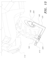
FIG. 13 shows a perspective environmental view of a wheel clamp according to the invention,
FIG. 14 shows a perspective front view of a wheel clamp according to the invention.
FIG. 15 shows an exploded view of a wheel clamp according to the invention.
FIG. 16 shows a perspective front view of a wheel clamp according to the invention.
FIG. 17 shows a perspective view of an outer hook with a plate attached thereto according to the invention.
FIG. 18A shows a front view of a wheel clamp according to the invention.
FIG. 18B shows a front view of a wheel clamp according to the invention,
FIG. 18C shows a front view of a wheel clamp according to the invention.
FIG. 19 shows a perspective environmental view of a wheel clamp according to the invention.
FIG. 20 shows a perspective environmental view of a wheel clamp according to the invention.
FIG. 21 is a table listing parts.
DETAILED DESCRIPTION OF THE INVENTION
It is to be understood that the terms “top” “bottom”, “left”, “right”, “side”, “front”, “rear”, “upper” “lower”, “vertical”, “horizontal”, “height”, “width”, “length”, “end” and the like are used herein merely to describe points of reference and do not limit the present invention to any specific orientation or configuration. It should also be understood that the claimed invention and parts may be of any size, shape or configuration suitable for operation of the invention and may be constructed of any suitable materials. Still further, any and all dimensions if shown in attached Figures are example dimensions; dimensions (length, width, height) can vary from those shown.
The wheel clamp 100 according to the present invention can be fitted, for example, to the driver's side front wheel (see, for example, FIG. 1 ) of a variety of vehicles which is to say the invention is not limited to a particular vehicle.
The wheel clamp 100 according to the invention is shown in the accompanying drawings clamped to an all-terrain vehicle (ATV) 110 (specifically, in FIGS. 1, 13, 19, and 20 ). However, it should be expressly understood that the wheel clamp 100 of the present invention can be used to clamp a variety of wheels and hence is expressly not limited to clamping an ATV's wheel.
Table 1 of parts (FIG. 21 ) is a useful point of reference with respect to the Figures.
Referring to the Figures in general, the wheel clamp 100 of the present invention comprises an outer hook 120, an inner hook 140, a plate member 160, and a lock mechanism 220 (the lock mechanism 220 is at least partly surrounded by a housing 240).
The outer hook 120 comprises a first outer hook member 300, a second outer hook member 320 and a third outer hook member 340. The second outer hook member 320 is located between the first outer hook member 300 and the third outer hook member 340. The first outer hook member 300 is connected to a bottom end 325 of the second outer hook member 320. The third outer hook member 340 is connected to a top end 335 of the second outer hook member 320. The third outer hook member 340 defines an angular shaped first end 350. (See, for example, FIG. 3 .) It should be understood that the first end 350 can adopt any suitable shape and hence is expressly not restricted to having an angular shape.
The inner hook 140 comprises a first inner hook member 400, a second inner hook member 420 and a third inner hook member 440. The second inner hook member 420 is located between the first inner hook member 400 and the third inner hook member 440. The first inner hook member 400 is connected to a bottom end 425 of the second inner hook member 420. The third inner hook member 440 is connected to a top end 435 of the second inner hook member 420. The third inner hook member 440 defines an angular shaped second end 450. It should be understood that the second end 450 can adopt any suitable shape and hence is expressly not restricted to having an angular shape. The second end 450 of the third inner hook member points inward toward the first end 350 of the third outer hook member 340.
The plate member 160 comprises a plate aperture 180 therethrough. A female receiving member 200 both surrounds and extends from the plate aperture 180. (See, for example, FIGS. 6 and 7 ). Hence the plate member 160 comprises the plate aperture 180 and the female receiving member 200. The female receiving member 200 receives the first end 350 of the third outer hook member 340. In normal use of the wheel clamp 100, the plate member 160 covers one or more wheel lugs.
The first inner hook member 400 is perforated to provide an inner hole 405. (See, for example, FIG. 8B in which the lock mechanism 220 and housing 240 are shown removed for the purpose of revealing inner hole 405). The first outer hook member 300 is perforated to provide a plurality of outer holes 410. (See, for example, FIGS. 1, 3, 5, and 13 ). Wherein when the inner hole 405 is aligned with one of the plurality of outer holes 410 the lock mechanism 220 is capable of engaging the inner hole 405 (see FIGS. 8B and 11 ) with one of the plurality of outer holes 410 to prevent movement of the first outer hook member 300 relative to the first inner hook member 400 and thereby preventing movement of the outer hook 120 relative to the inner hook 140.
In one non-limiting embodiment, the first inner hook member 400 is further perforated to provide a plurality of inner holes 415. (See, for example, FIG. 8C in which the lock mechanism 220 and housing 240 are shown removed for the purpose of revealing the plurality of inner holes 415). Wherein when one of the inner holes 415 is aligned with one of the plurality of outer holes 410 the lock mechanism is capable of engaging at least one of the plurality of inner holes 415 with one of the plurality of outer holes 410 to prevent movement of the first outer hook member 300 relative to the first inner hook member 400 and thereby preventing movement of the outer hook 120 relative to the inner hook 140.
The lock mechanism 220 can be any suitable lock. In one non-limiting embodiment, the lock mechanism 220 is a barrel lock 230. (See, for example, FIGS. 3, 8A, 11, and 12 ).
In one non-limiting embodiment, a 220 lock cap 225 covers at least a part of the lock mechanism 220 to keep out dust and unwanted detritus. (See, for example, FIGS. 2 and 3 ).
In one non-limiting embodiment, the wheel clamp 100 further comprises a nail like projection 600 extending from an inner side 620 of the first outer hook member 300. (See, for example, FIG. 8A). The purpose of the nail like projection 600 is to increase the possibility of causing a flat tire should someone interfere with the wheel clamp 100 thereby reducing the risk of theft or illicit use of the vehicle.
In one non-limiting embodiment, the wheel clamp 100 further comprises an elongated extension member 640 that extends from the third inner hook member 440 (see, for example, FIGS. 8A and 18A); the elongated extension member 640 defines an upper side 680, a tubular member 660 is attached to the upper side 680, the tubular member 660 being parallel to the elongated extension member 640 (see, for example, FIGS. 9 and 10 ).
In one non-limiting embodiment, the outer hook 120 adopts a first generally rectangular u-shaped configuration, and the inner hook 140 adopts a second generally rectangular u-shaped configuration, wherein the outer hook and inner hook face each other.
In one non-limiting embodiment, a first angular cap 360 fits over the angular shaped first end 350; and a second angular cap 460 fits over the angular shaped second end 450. (See, for example, FIGS. 3 and 15 ).
In one non-limiting embodiment, during normal operation of the wheel clamp 100 the female receiving member 200 receives the angular shaped first end 350 of the third outer hook member 340 whereupon a first angular cap 360 is fitted over the first end 350.
In one non-limiting embodiment, the outer hook 120 defines a first hollow square cross-section 122; and the inner hook 140 defines a second hollow square cross-section 142. (See, for example, FIGS. 3 and 15 ). The nature of the hollow cross-section of the outer hook 120 and inner hook 140 can vary and, for example, can take the form of a hollow rectangular cross-section.
In one non-limiting embodiment, the wheel clamp 100 comprises the plate member 160 as well as an elongated extension member 640 that extends from the third inner hook member 440; the elongated extension member 640 defines an upper side 680, a tubular member 660 is attached to the upper side 680, the tubular member 660 being parallel to the elongated extension member 640 (see, for example, FIG. 188 ).
In one non-limiting embodiment, the wheel clamp 100 comprises nail like projection 600, and the plate member 160 as well as an elongated extension member 640 that extends from the third inner hook member 440; the elongated extension member 640 defines an upper side 680, a tubular member 660 is attached to the upper side 680, the tubular member 660 being parallel to the elongated extension member 640 (see, for example, FIG. 18C).
In one non-limiting embodiment, the wheel clamp 100 lacks the plate member 160, i.e., the plate aperture 180 therethrough, and further lacks a female receiving member 200 as shown in FIGS. 19 and 20 .
In one non-limiting embodiment, the wheel clamp 100 is made of steel.
In one non-limiting embodiment, the wheel clamp 100 is made of composite material.
In one non-limiting embodiment, the wheel clamp 100 is made of a combination of composite material and steel. For example, the amount of composite can vary between 5% and 95% the remaining being steel, and vice versa.
The composite material can take any suitable form such as, but not limited to, fiber-reinforced plastic.
Patents which explain how to make and mould fiber-reinforced plastics include, alone or in combination, as follows: U.S. Pat. No. 4,255,087 (to Wackerle, et al, “Member formed of fiber-reinforced plastic material, such as a rotor blade”), U.S. Pat. No. 4,188,032 (to Yanagiok, “Nickel-plated golf club shaft made of fiber-reinforced plastics”), U.S. Pat. No. 4,339,490 (to Yoshioka, et al, “Fiber reinforced plastic sheet molding compound”), U.S. Pat. No. 4,696,459 (to Woltron, et al. “Plastic leaf spring with at least one spring-eye body or spring-eye section”), U.S. Pat. No. 4,671,842 (to Prochaska, et al, “System for the manufacture of tubular structural parts of a fiber-reinforced plastic”), U.S. Pat. No. 4,234,190 (to Airhart, “Carbon fiber-reinforced plastic arrow”), U.S. Pat. No. 6,797,331 (to Singler, et al, “Process for producing a chemical-resistant protective layer for a rotary body having a base body made from fiber-reinforced plastic”), U.S. Pat. No. 5,665,470 (to Key, et al, “Glass fibers and fiber-reinforced plastics”), U.S. Pat. No. 5,601,493 (to Nakazono, et al, “Drive shaft made of fiber reinforced plastics, and method for connecting pipe made of fire-reinforced plastics”), U.S. Pat. No. 5,534,318 (to Andre De La Porte, et al, “Hollow fiber-reinforced plastic body”), U.S. Pat. No. 10,611,057 (to Taketa, et al), U.S. Pat. No. 9,751,239 (to Murai, et al, “Method and device for molding fiber-reinforced plastic member”), U.S. Pat. No. 9,574,081 (to Ishimoto, et al, “Epoxy-resin composition, and film, prepreg and fiber-reinforced plastic using the same”), U.S. Pat. No. 9,168,801 (to Dicke, et al, “Transverse link made of fibre-reinforced plastics material for a wheel suspension of a vehicle”), U.S. Pat. No. 7,083,199 (to Graber, et al, “Chassis part consisting of fiber-reinforced plastics, equipped with an integrated sensor”), U.S. Pat. No. 8,376,426 (to Choi, et al, “Plastic composite bumper beam for vehicle”) U.S. Pat. No. 10,773,472 (to Takano, et al, “Method for manufacturing fiber-reinforced plastic molded body”), and U.S. Pat. No. 10,227,464 (to Saji, “Fiber-reinforced plastic shaped product”).
Composite materials that can also be used in the present invention include those described in; U.S. Pat. No. 11,220,465 (to Kube, et al, “Method for producing SiC/SiC composite material”), U.S. Pat. No. 11,208,535 (to Ochi, et al, “Production method for prepreg, and production method for fiber-reinforced composite material”), U.S. Pat. No. 11,203,178 (to Kuroda, “Reinforced substrate for composite material, composite material, and method for manufacturing reinforced substrate for composite material”), U.S. Pat. No. 11,187,09 (to Ochi, et al, “Coating-liquid-impregnated fiber-reinforced fabric, sheet-shaped integrated object, prepreg, prepreg tape, and method for manufacturing fiber-reinforced composite material”), U.S. Pat. No. 11,208,911 (to Sadler, et al, “Turbine shroud ring segments with ceramic matrix composite components”), U.S. Pat. No. 11,198,651 (to Sadler, et al, “Turbine shroud ring segments with ceramic matrix composite components”)”); and U.S. Pat. No. 11,198,924 (to Chandrasekaran, et al, “Composite materials”).
It is to be understood that the present invention is not limited to the embodiments described above, but encompasses any and all embodiments within the scope of the following claims.

Claims (15)

What is claimed:
1. A wheel clamp, comprising:
an outer hook;
an inner hook;
a plate member having a plate aperture therethrough, wherein a female receiving member both surrounds and extends from the plate aperture;
wherein the outer hook comprises a first outer hook member, a second outer hook member, and a third outer hook member,
wherein the female receiving member receives a first end of the third outer hook member,
wherein the inner hook comprises a first inner hook member, a second inner hook member, and a third inner hook member,
a lock mechanism, wherein the lock mechanism is at least partly surrounded by a housing, wherein the lock mechanism and housing form part of the first inner hook member,
wherein an elongated extension member extends from the third inner hook member, wherein the extension member is located directly opposite the plate member,
wherein the elongated extension member defines an upper side, wherein a tubular member is attached to the upper side,
wherein the first inner hook member is perforated to provide an inner hole, the first outer hook member is perforated to provide a plurality of outer holes, wherein when the inner hole is aligned with one of the plurality of the outer holes the lock mechanism is capable of engaging the inner hole with one of the plurality of outer holes to prevent movement of the first outer hook member relative to the first inner hook member and thereby preventing movement of the outer hook relative to the inner hook.
2. The wheel clamp according to claim 1, further comprises a nail like projection extending from an inner side of the first outer hook member.
3. The wheel clamp according to claim 1, wherein the tubular member is parallel to the elongated extension member.
4. The wheel clamp according to claim 1, wherein the first end defines an angular shape.
5. The wheel clamp according to claim 1, wherein the wheel clamp is made of composite material.
6. The wheel clamp according to claim 1, wherein the wheel clamp is made of steel.
7. The wheel clamp according to claim 2, wherein the wheel clamp is made of a combination of composite material and steel.
8. The wheel clamp according to claim 1, wherein the outer hook adopts a first generally rectangular u-shaped configuration and the inner hook adopts a second generally rectangular u-shaped configuration, wherein the outer hook and inner hook face each other.
9. A wheel clamp, comprising:
an outer hook, the outer hook comprises a first outer hook member, a second outer hook member and a third outer hook member, wherein the second outer hook member is located between the first outer hook member and the third outer hook member, the first outer hook member is connected to a bottom end of the second outer hook member, the third outer hook member being connected to a top end of the second outer hook member;
an inner hook, wherein the inner hook comprises a first inner hook member, a second inner hook member, and a third inner hook member, wherein the outer hook adopts a first generally rectangular u-shaped configuration, and the inner hook adopts a second generally rectangular u-shaped configuration, wherein the outer hook and inner hook face each other;
a plate member having a plate aperture therethrough, wherein a female receiving member both surrounds and extends from the plate aperture, wherein the female receiving member receives a first end of the third outer hook member; and
a lock mechanism, wherein the lock mechanism is at least partly surrounded by a housing, wherein the lock mechanism and housing form part of the first inner hook member,
wherein an elongated extension member extends from the third inner hook member, wherein the extension member is located directly opposite the plate member, the elongated extension member defines an upper side, a tubular member is attached to the upper side, the tubular member being parallel to the elongated extension member,
wherein the first inner hook member is perforated to provide an inner hole, the first outer hook member is perforated to provide a plurality of outer holes, wherein when the inner hole is aligned with one of the plurality of outer holes the lock mechanism is capable of engaging the inner hole with one of the plurality of outer holes to prevent movement of the first outer hook member relative to the first inner hook member and thereby preventing movement of the outer hook relative to the inner hook.
10. The wheel clamp according to claim 9, wherein the lock mechanism is a barrel lock.
11. The wheel clamp according to claim 9, further comprises a nail like projection extending from an inner side of the first outer hook member.
12. The wheel clamp according to claim 9, wherein the wheel clamp is made of composite material.
13. The wheel clamp according to claim 9, wherein the wheel clamp is made of steel.
14. The wheel clamp according to claim 9, wherein the wheel clamp is made of a combination of composite material and steel.
15. A wheel clamp, comprising:
an outer hook;
an inner hook;
a plate member having a plate aperture therethrough, wherein a female receiving member both surrounds and extends from the plate aperture;
wherein the outer hook comprises a first outer hook member, a second outer hook member, and a third outer hook member,
wherein the female receiving member receives a first end of the third outer hook member,
wherein the inner hook comprises a first inner hook member, a second inner hook member, and a third inner hook member,
a lock mechanism, wherein the lock mechanism is at least partly surrounded by a housing, wherein the lock mechanism and housing form part of the first inner hook member, wherein the lock mechanism is a barrel lock,
wherein an elongated extension member extends from the third inner hook member,
wherein an elongated extension member extends from the third inner hook member, wherein the extension member is located directly opposite the plate member,
wherein the elongated extension member defines an upper side, wherein a tubular member is attached to the upper side,
wherein the first inner hook member is perforated to provide an inner hole, the first outer hook member is perforated to provide a plurality of outer holes, wherein when the inner hole is aligned with one of the plurality of the outer holes the barrel lock is capable of engaging the inner hole with one of the plurality of outer holes to prevent movement of the first outer hook member relative to the first inner hook member and thereby preventing movement of the outer hook relative to the inner hook.
US18/197,720 2022-06-17 2023-05-16 Wheel clamp Active 2043-07-14 US12344192B2 (en)

Priority Applications (2)

Application Number Priority Date Filing Date Title
US18/197,720 US12344192B2 (en) 2022-06-17 2023-05-16 Wheel clamp
US19/241,349 US20250313174A1 (en) 2022-06-17 2025-06-17 Wheel Clamp

Applications Claiming Priority (2)

Application Number Priority Date Filing Date Title
US202263353037P 2022-06-17 2022-06-17
US18/197,720 US12344192B2 (en) 2022-06-17 2023-05-16 Wheel clamp

Related Child Applications (1)

Application Number Title Priority Date Filing Date
US19/241,349 Division US20250313174A1 (en) 2022-06-17 2025-06-17 Wheel Clamp

Publications (2)

Publication Number Publication Date
US20230407681A1 US20230407681A1 (en) 2023-12-21
US12344192B2 true US12344192B2 (en) 2025-07-01

Family

ID=89169402

Family Applications (2)

Application Number Title Priority Date Filing Date
US18/197,720 Active 2043-07-14 US12344192B2 (en) 2022-06-17 2023-05-16 Wheel clamp
US19/241,349 Pending US20250313174A1 (en) 2022-06-17 2025-06-17 Wheel Clamp

Family Applications After (1)

Application Number Title Priority Date Filing Date
US19/241,349 Pending US20250313174A1 (en) 2022-06-17 2025-06-17 Wheel Clamp

Country Status (1)

Country Link
US (2) US12344192B2 (en)

Citations (47)

* Cited by examiner, † Cited by third party
Publication number Priority date Publication date Assignee Title
US2960857A (en) * 1958-11-24 1960-11-22 Rhino Products Corp Automobile wheel chock
US4188032A (en) 1976-05-19 1980-02-12 Seiichi Yanagioka Nickel-plated golf club shaft made of fiber-reinforced plastics
US4234190A (en) 1978-02-06 1980-11-18 Skyline Industries, Inc. Carbon fiber-reinforced plastic arrow
US4255087A (en) 1978-06-19 1981-03-10 Messerschmitt-Bolkow-Blohm Gmbh Member formed of fiber-reinforced plastic material, such as a rotor blade
US4339490A (en) 1979-09-12 1982-07-13 Mitsubishi Rayon Company, Limited Fiber reinforced plastic sheet molding compound
US4671842A (en) 1983-12-13 1987-06-09 Messerschmitt-Boelkow-Blohm Gmbh System for the manufacture of tubular structural parts of a fiber-reinforced plastic
US4696459A (en) 1984-03-02 1987-09-29 Isoport Verbundbauteile Ges. m.b.H. Plastic leaf spring with at least one spring-eye body or spring-eye section
US4819462A (en) * 1987-05-06 1989-04-11 Micrologic, Inc. Locking clamp for a trailer tire-carrying wheel and the like
US4854144A (en) * 1987-08-17 1989-08-08 Double Helix Enterprises Vehicle immobilization device
US5315848A (en) * 1993-01-19 1994-05-31 Beyer Terrance L Wheel lock
US5375442A (en) * 1993-04-28 1994-12-27 Hammer; Robert N. Clamp assembly for a trailer or like wheeled vehicle
US5534318A (en) 1991-03-18 1996-07-09 Parabeam Industrie-En Handelsonderneming B.V. Hollow fiber-reinforced plastic body
US5601493A (en) 1992-10-22 1997-02-11 Sumitomo Chemical Company Limited Drive shaft made of fiber reinforced plastics, and method for connecting pipe made of fire-reinforced plastics
US5665470A (en) 1994-07-27 1997-09-09 National Starch And Chemical Investment Holding Corporation Glass fibers and fiber-reinforced plastics
US6173590B1 (en) 2000-01-27 2001-01-16 Bryan Witchey Skid steer lock
US20020104336A1 (en) 2001-02-05 2002-08-08 Bryan Witchey Backhoe lock
US20020104342A1 (en) 2001-02-05 2002-08-08 Bryan Witchey Skid steer lock
US20020104340A1 (en) 2001-02-05 2002-08-08 Bryan Witchey E-series skid steer lock
US20030167805A1 (en) 2002-03-11 2003-09-11 Bryan Witchey Skid steer attachment lock
US20030167807A1 (en) 2002-03-11 2003-09-11 Bryan Witchey Excavator lock
US20030167806A1 (en) 2002-03-11 2003-09-11 Bryan Witchey Ball and ring hitch lock
US6797331B2 (en) 2001-06-08 2004-09-28 Man Roland Druckmaschinen Ag Process for producing a chemical-resistant protective layer for a rotary body having a base body made from fiber-reinforced plastic
US20040200246A1 (en) 2003-04-14 2004-10-14 Bryan Witchey Changeable combination skidsteer lock
US20050099018A1 (en) 2003-11-12 2005-05-12 Bryan Witchey Cargo door lock
US7083199B2 (en) 2001-11-06 2006-08-01 ZF Lemförder Metallwaren AG Chassis part consisting of fiber-reinforced plastics, equipped with an integrated sensor
US20060220347A1 (en) 2005-03-29 2006-10-05 Bryan Witchey Hitch storage device
US20070228693A1 (en) 2006-03-29 2007-10-04 Bryan Witchey Hitch storage device
US7337636B2 (en) 2005-03-29 2008-03-04 Bryan Witchey Anti-theft device
US8376426B2 (en) 2011-05-31 2013-02-19 Hyundai Motor Company Plastic composite bumper beam for vehicle
US9168801B2 (en) 2013-01-28 2015-10-27 Gestamp Umformtechnik Gmbh Transverse link made of fibre-reinforced plastics material for a wheel suspension of a vehicle
US9574081B2 (en) 2012-08-20 2017-02-21 Mitsubishi Rayon Co., Ltd. Epoxy-resin composition, and film, prepreg and fiber-reinforced plastic using the same
US9751239B2 (en) 2013-06-04 2017-09-05 Mitsubishi Aircraft Corporation Method and device for molding fiber-reinforced plastic member
US20180010369A1 (en) 2016-07-11 2018-01-11 Bryan Witchey Rolling door lock
US9963105B1 (en) * 2017-07-19 2018-05-08 Mike Gordon Locking boot for vehicle wheel
US20180194320A1 (en) 2017-01-11 2018-07-12 Bryan Witchey Landing gear leg lock
US10227464B2 (en) 2014-03-20 2019-03-12 Teijin Limited Fiber-reinforced plastic shaped product
US20200070774A1 (en) * 2017-05-11 2020-03-05 Cimmino-Cotona Partnership Assembly, system and method of an electronic wheel locking assembly (boot) with wireless unlocking
US10611057B2 (en) 2014-09-19 2020-04-07 Toray Industries, Inc. Process of producing fiber-reinforced plastic
US10773472B2 (en) 2015-06-02 2020-09-15 Mitsubishi Chemical Corporation Method for manufacturing fiber-reinforced plastic molded body
US20210213649A1 (en) 2018-06-05 2021-07-15 Toray Industries, Inc. Coating-liquid-impregnated fiber-reinforced fabric, sheet-shaped integrated object, prepreg, prepreg tape, and method for manufacturing fiber-reinforced composite material
US11198924B2 (en) 2004-10-28 2021-12-14 Qinetiq Limited Composite materials
US11198651B2 (en) 2018-12-20 2021-12-14 Rolls-Royce High Temperature Composites, Inc. Surface layer on a ceramic matrix composite
US11203178B2 (en) 2016-11-01 2021-12-21 Nissan Motor Co., Ltd. Reinforced substrate for composite material, composite material, and method for manufacturing reinforced substrate for composite material
US11208911B2 (en) 2020-04-23 2021-12-28 Rolls-Royce Plc Turbine shroud ring segments with ceramic matrix composite components
US11208535B2 (en) 2017-03-22 2021-12-28 Toray Industries, Inc. Production method for prepreg, and production method for fiber-reinforced composite material
US11220465B2 (en) 2017-05-25 2022-01-11 Ibiden Co., Ltd. Method for producing SiC/SiC composite material
US20220396239A1 (en) * 2021-06-15 2022-12-15 John Clarke Wheel immobilizer

Patent Citations (58)

* Cited by examiner, † Cited by third party
Publication number Priority date Publication date Assignee Title
US2960857A (en) * 1958-11-24 1960-11-22 Rhino Products Corp Automobile wheel chock
US4188032A (en) 1976-05-19 1980-02-12 Seiichi Yanagioka Nickel-plated golf club shaft made of fiber-reinforced plastics
US4234190A (en) 1978-02-06 1980-11-18 Skyline Industries, Inc. Carbon fiber-reinforced plastic arrow
US4255087A (en) 1978-06-19 1981-03-10 Messerschmitt-Bolkow-Blohm Gmbh Member formed of fiber-reinforced plastic material, such as a rotor blade
US4339490A (en) 1979-09-12 1982-07-13 Mitsubishi Rayon Company, Limited Fiber reinforced plastic sheet molding compound
US4671842A (en) 1983-12-13 1987-06-09 Messerschmitt-Boelkow-Blohm Gmbh System for the manufacture of tubular structural parts of a fiber-reinforced plastic
US4696459A (en) 1984-03-02 1987-09-29 Isoport Verbundbauteile Ges. m.b.H. Plastic leaf spring with at least one spring-eye body or spring-eye section
US4819462A (en) * 1987-05-06 1989-04-11 Micrologic, Inc. Locking clamp for a trailer tire-carrying wheel and the like
US4854144A (en) * 1987-08-17 1989-08-08 Double Helix Enterprises Vehicle immobilization device
US5534318A (en) 1991-03-18 1996-07-09 Parabeam Industrie-En Handelsonderneming B.V. Hollow fiber-reinforced plastic body
US5601493A (en) 1992-10-22 1997-02-11 Sumitomo Chemical Company Limited Drive shaft made of fiber reinforced plastics, and method for connecting pipe made of fire-reinforced plastics
US5315848A (en) * 1993-01-19 1994-05-31 Beyer Terrance L Wheel lock
US5375442A (en) * 1993-04-28 1994-12-27 Hammer; Robert N. Clamp assembly for a trailer or like wheeled vehicle
US5665470A (en) 1994-07-27 1997-09-09 National Starch And Chemical Investment Holding Corporation Glass fibers and fiber-reinforced plastics
US6173590B1 (en) 2000-01-27 2001-01-16 Bryan Witchey Skid steer lock
US20020104342A1 (en) 2001-02-05 2002-08-08 Bryan Witchey Skid steer lock
US20020104340A1 (en) 2001-02-05 2002-08-08 Bryan Witchey E-series skid steer lock
US6519983B2 (en) 2001-02-05 2003-02-18 Bryan Witchey Backhoe lock
US6539757B2 (en) 2001-02-05 2003-04-01 Bryan Witchey E-series skid steer lock
US6553797B2 (en) 2001-02-05 2003-04-29 Bryan Witchey Skid steer lock
US20020104336A1 (en) 2001-02-05 2002-08-08 Bryan Witchey Backhoe lock
US6797331B2 (en) 2001-06-08 2004-09-28 Man Roland Druckmaschinen Ag Process for producing a chemical-resistant protective layer for a rotary body having a base body made from fiber-reinforced plastic
US7083199B2 (en) 2001-11-06 2006-08-01 ZF Lemförder Metallwaren AG Chassis part consisting of fiber-reinforced plastics, equipped with an integrated sensor
US20030167805A1 (en) 2002-03-11 2003-09-11 Bryan Witchey Skid steer attachment lock
US6698256B2 (en) 2002-03-11 2004-03-02 Bryan Witchey Ball and ring hitch lock
US6705135B2 (en) 2002-03-11 2004-03-16 Bryan Witchey Excavator lock
US20030167806A1 (en) 2002-03-11 2003-09-11 Bryan Witchey Ball and ring hitch lock
US6990838B2 (en) 2002-03-11 2006-01-31 Bryan Witchey Skid steer attachment lock
US20030167807A1 (en) 2002-03-11 2003-09-11 Bryan Witchey Excavator lock
US20040200246A1 (en) 2003-04-14 2004-10-14 Bryan Witchey Changeable combination skidsteer lock
US7278663B2 (en) 2003-11-12 2007-10-09 Bryan Witchey Cargo door lock
US20050099018A1 (en) 2003-11-12 2005-05-12 Bryan Witchey Cargo door lock
US11198924B2 (en) 2004-10-28 2021-12-14 Qinetiq Limited Composite materials
US20060220347A1 (en) 2005-03-29 2006-10-05 Bryan Witchey Hitch storage device
US7337636B2 (en) 2005-03-29 2008-03-04 Bryan Witchey Anti-theft device
US20070228693A1 (en) 2006-03-29 2007-10-04 Bryan Witchey Hitch storage device
US7815211B2 (en) 2006-03-29 2010-10-19 Bryan Witchey Hitch storage device
US8376426B2 (en) 2011-05-31 2013-02-19 Hyundai Motor Company Plastic composite bumper beam for vehicle
US9574081B2 (en) 2012-08-20 2017-02-21 Mitsubishi Rayon Co., Ltd. Epoxy-resin composition, and film, prepreg and fiber-reinforced plastic using the same
US9168801B2 (en) 2013-01-28 2015-10-27 Gestamp Umformtechnik Gmbh Transverse link made of fibre-reinforced plastics material for a wheel suspension of a vehicle
US9751239B2 (en) 2013-06-04 2017-09-05 Mitsubishi Aircraft Corporation Method and device for molding fiber-reinforced plastic member
US10227464B2 (en) 2014-03-20 2019-03-12 Teijin Limited Fiber-reinforced plastic shaped product
US10611057B2 (en) 2014-09-19 2020-04-07 Toray Industries, Inc. Process of producing fiber-reinforced plastic
US10773472B2 (en) 2015-06-02 2020-09-15 Mitsubishi Chemical Corporation Method for manufacturing fiber-reinforced plastic molded body
US10240371B2 (en) 2016-07-11 2019-03-26 Bryan Witchey Rolling door lock
US20180010369A1 (en) 2016-07-11 2018-01-11 Bryan Witchey Rolling door lock
US11203178B2 (en) 2016-11-01 2021-12-21 Nissan Motor Co., Ltd. Reinforced substrate for composite material, composite material, and method for manufacturing reinforced substrate for composite material
US20180194320A1 (en) 2017-01-11 2018-07-12 Bryan Witchey Landing gear leg lock
US10272873B2 (en) 2017-01-11 2019-04-30 Bryan Witchey Landing gear leg lock
US11208535B2 (en) 2017-03-22 2021-12-28 Toray Industries, Inc. Production method for prepreg, and production method for fiber-reinforced composite material
US20200070774A1 (en) * 2017-05-11 2020-03-05 Cimmino-Cotona Partnership Assembly, system and method of an electronic wheel locking assembly (boot) with wireless unlocking
US11220465B2 (en) 2017-05-25 2022-01-11 Ibiden Co., Ltd. Method for producing SiC/SiC composite material
US9963105B1 (en) * 2017-07-19 2018-05-08 Mike Gordon Locking boot for vehicle wheel
US11192280B2 (en) 2018-06-05 2021-12-07 Toray Industries, Inc. Coating-liquid-impregnated fiber-reinforced fabric, sheet-shaped integrated object, prepreg, prepreg tape, and method for manufacturing fiber-reinforced composite material
US20210213649A1 (en) 2018-06-05 2021-07-15 Toray Industries, Inc. Coating-liquid-impregnated fiber-reinforced fabric, sheet-shaped integrated object, prepreg, prepreg tape, and method for manufacturing fiber-reinforced composite material
US11198651B2 (en) 2018-12-20 2021-12-14 Rolls-Royce High Temperature Composites, Inc. Surface layer on a ceramic matrix composite
US11208911B2 (en) 2020-04-23 2021-12-28 Rolls-Royce Plc Turbine shroud ring segments with ceramic matrix composite components
US20220396239A1 (en) * 2021-06-15 2022-12-15 John Clarke Wheel immobilizer

Also Published As

Publication number Publication date
US20250313174A1 (en) 2025-10-09
US20230407681A1 (en) 2023-12-21

Similar Documents

Publication Publication Date Title
US8636162B2 (en) Fuel tank shell with structural support
US20200276861A1 (en) Wheel comprising a non-pneumatic tire
CN102434722B (en) Clamp member
US12344192B2 (en) Wheel clamp
US7273230B2 (en) Tension shackle x-brace
US20110036654A1 (en) Moulded plastic part for accommodating a vehicle battery
US20040051373A1 (en) Flexible rim wheel with resilient spokes
JP2010101385A (en) Bush
JP6798973B2 (en) Vehicle resin parts
US20100186467A1 (en) Spare tire and rim theft prevention device
JP6798974B2 (en) Vehicle resin parts
US20050104314A1 (en) Bracket of steering rack housing
US20240375609A1 (en) Wheel to Pedal Lock
US9878519B2 (en) Fender for straddled vehicles and straddled vehicle
EP1937502B1 (en) Tank assembly
KR102687390B1 (en) Door impact beam for car vehicle and preparing method thereof
JP5437025B2 (en) Vibration isolator
US617836A (en) Mud-guard
US20190135209A1 (en) Lower Stiffener for Bumper of Vehicle
JP5318731B2 (en) Vibration isolator
CN111163954A (en) Arm for motor vehicle and method for manufacturing arm for motor vehicle
CN1697753A (en) Handle part mounter and handle part mounting structure
CN106573638B (en) Steering column with hybrid component as support structure
KR20200080126A (en) composite material bush
CN107826169A (en) A kind of automobile B-pillar reinforcement plate and its manufacture method

Legal Events

Date Code Title Description
FEPP Fee payment procedure

Free format text: ENTITY STATUS SET TO UNDISCOUNTED (ORIGINAL EVENT CODE: BIG.); ENTITY STATUS OF PATENT OWNER: SMALL ENTITY

FEPP Fee payment procedure

Free format text: ENTITY STATUS SET TO SMALL (ORIGINAL EVENT CODE: SMAL); ENTITY STATUS OF PATENT OWNER: SMALL ENTITY

STPP Information on status: patent application and granting procedure in general

Free format text: DOCKETED NEW CASE - READY FOR EXAMINATION

STPP Information on status: patent application and granting procedure in general

Free format text: NON FINAL ACTION MAILED

STPP Information on status: patent application and granting procedure in general

Free format text: RESPONSE TO NON-FINAL OFFICE ACTION ENTERED AND FORWARDED TO EXAMINER

STPP Information on status: patent application and granting procedure in general

Free format text: NON FINAL ACTION MAILED

STCF Information on status: patent grant

Free format text: PATENTED CASE