US12328183B2 - Method for avoiding function disablements for intelligent electronic units - Google Patents
Method for avoiding function disablements for intelligent electronic units Download PDFInfo
- Publication number
- US12328183B2 US12328183B2 US18/796,558 US202418796558A US12328183B2 US 12328183 B2 US12328183 B2 US 12328183B2 US 202418796558 A US202418796558 A US 202418796558A US 12328183 B2 US12328183 B2 US 12328183B2
- Authority
- US
- United States
- Prior art keywords
- grandmaster
- timing unit
- timing
- role
- ieds
- Prior art date
- Legal status (The legal status is an assumption and is not a legal conclusion. Google has not performed a legal analysis and makes no representation as to the accuracy of the status listed.)
- Active
Links
Images


Classifications
-
- H—ELECTRICITY
- H04—ELECTRIC COMMUNICATION TECHNIQUE
- H04W—WIRELESS COMMUNICATION NETWORKS
- H04W56/00—Synchronisation arrangements
- H04W56/001—Synchronization between nodes
-
- H—ELECTRICITY
- H04—ELECTRIC COMMUNICATION TECHNIQUE
- H04J—MULTIPLEX COMMUNICATION
- H04J3/00—Time-division multiplex systems
- H04J3/02—Details
- H04J3/06—Synchronising arrangements
- H04J3/0635—Clock or time synchronisation in a network
- H04J3/0638—Clock or time synchronisation among nodes; Internode synchronisation
- H04J3/0641—Change of the master or reference, e.g. take-over or failure of the master
-
- H02J13/36—
-
- H—ELECTRICITY
- H04—ELECTRIC COMMUNICATION TECHNIQUE
- H04J—MULTIPLEX COMMUNICATION
- H04J3/00—Time-division multiplex systems
- H04J3/02—Details
- H04J3/06—Synchronising arrangements
- H04J3/0635—Clock or time synchronisation in a network
- H04J3/0638—Clock or time synchronisation among nodes; Internode synchronisation
- H04J3/0658—Clock or time synchronisation among packet nodes
- H04J3/0661—Clock or time synchronisation among packet nodes using timestamps
- H04J3/0667—Bidirectional timestamps, e.g. NTP or PTP for compensation of clock drift and for compensation of propagation delays
-
- H—ELECTRICITY
- H04—ELECTRIC COMMUNICATION TECHNIQUE
- H04W—WIRELESS COMMUNICATION NETWORKS
- H04W56/00—Synchronisation arrangements
- H04W56/001—Synchronization between nodes
- H04W56/0015—Synchronization between nodes one node acting as a reference for the others
-
- H—ELECTRICITY
- H02—GENERATION; CONVERSION OR DISTRIBUTION OF ELECTRIC POWER
- H02J—CIRCUIT ARRANGEMENTS OR SYSTEMS FOR SUPPLYING OR DISTRIBUTING ELECTRIC POWER; SYSTEMS FOR STORING ELECTRIC ENERGY
- H02J3/00—Circuit arrangements for AC mains or AC distribution networks
- H02J3/001—Methods to deal with contingencies, e.g. abnormalities, faults or failures
-
- H—ELECTRICITY
- H04—ELECTRIC COMMUNICATION TECHNIQUE
- H04J—MULTIPLEX COMMUNICATION
- H04J3/00—Time-division multiplex systems
- H04J3/02—Details
- H04J3/12—Arrangements providing for calling or supervisory signals
-
- H—ELECTRICITY
- H04—ELECTRIC COMMUNICATION TECHNIQUE
- H04W—WIRELESS COMMUNICATION NETWORKS
- H04W84/00—Network topologies
- H04W84/02—Hierarchically pre-organised networks, e.g. paging networks, cellular networks, WLAN [Wireless Local Area Network] or WLL [Wireless Local Loop]
- H04W84/10—Small scale networks; Flat hierarchical networks
- H04W84/12—WLAN [Wireless Local Area Networks]
Definitions
- the protocol is referred to as the Precision Time Protocol and is hereinafter referred to as the PTP.
- a local area network is implemented in electrical power supply substations.
- Such substations are used to lower or raise the mains voltages prevailing in the supply grid by means of a transformer whose mode of operation is known.
- substations have switching units such as circuit breakers that, after receiving a switching signal, disconnect conductor outgoers of the substation from the rest of the supply grid.
- switching signals are generated by protection and automation devices that monitor the current and voltage characteristics in the conductors of the substation for the presence of fault conditions. If there is a fault condition, a switching signal is generated and transmitted to one or more selected switching units so that the switching units are moved to their disconnect position. In the disconnect position, the contacts of the selected switching units are separated from one another, preventing a flow of current via the switching units. A conductor run connected to one contact of said switching unit is then disconnected from the rest of the supply grid, which is connected to the other contact of said switching unit.
- the protection and automation devices In order for the protection and automation devices to be able to monitor the current and voltage characteristics in the conductors of the substation for the presence of fault conditions, they must be continuously supplied with time-dependent current and voltage values.
- current and voltage transformers that record current and voltage in the conductors at a measuring point of the substation and provide a calibrated measurement signal on the secondary side, which signal is sampled at a specified sampling rate to obtain samples. The samples are then digitized.
- a time stamp is permanently assigned to the samples. This is done by means of so-called “merging units” or using other intelligent electronic devices (IEDs) in the substation.
- IEDs intelligent electronic devices
- the time recording of the IEDs connected to one another via a process bus In order to be able to compare the measured values with one another, the time recording of the IEDs connected to one another via a process bus must be synchronized. This is accomplished using said PTP (Precision Time Protocol).
- the protocol PTP is thus used in digital electrical power supply substations to synchronize intelligent electronic devices (IEDs), for example in the so-called IEC 61850 process bus.
- IEDs intelligent electronic devices
- the comparability of the measured values originating from different IEDs is critical. Lost or insufficient time synchronization between these devices leads to the protection functions in the protection and automation devices being disabled or to a switching unit being erroneously tripped, with unintended interruption of the power supply as a result.
- a digital substation typically produces a digital process bus environment.
- Current and voltage in the high-voltage conductors is measured for example using current and voltage transformers that provide analog measured values on the output side. These analog measured values are separated from the protection device on the digital side by a special device referred to by those skilled in the art as a merging unit (MU).
- MU merging unit
- a merging unit provides a digital stream of samples. This data stream contains data telegrams that typically comply with the IEC 61850-9-2 standard.
- the protection device which assumes the role of a data telegram receiver, or sampled value subscriber (SV-SUB), in the digital network, registers for a multiplicity of data streams of different MUs, converts the data streams by way of digital filtering, rates the quality and synchronization attributes of the data and makes the converted data available to the protection or other functional algorithms.
- SV-SUB sampled value subscriber
- a differential protection system thus checks that the sum of the currents measured on all sides of a protection object in the fault-free state is equal to zero. Erroneous synchronization leads to a phase difference between the measured data streams and thus to an apparent differential current. This can lead to false tripping. Even in the case of distance protection, incorrect synchronization of the measured value acquisition between current and voltage leads to an incorrect impedance.
- the function of the IEDs will be disabled. For example, protection devices lose their protection function.
- the function of IEDs can be disabled as a result of the detection of step changes in the synchronization time base. Checking the identity of the synchronization source can also produce the same result.
- a common synchronization source is used for all devices that are involved.
- the preferred synchronization method described in the IEC 61850 standard is the IEEE 1588 Precision Time Protocol (PTP).
- PTP Precision Time Protocol
- GMC PTP grandmaster clocks
- BMCA best master clock algorithm
- the invention recognizes that a disablement of the function may be unnecessary when the synchronization source is changed. This is the case when the grandmaster role changes between timing units that are synchronized with one another.
- the present invention proposes methods for avoiding function disablements for intelligent electronic units IEDs that are connected to one another as part of a local network and via the local area network.
- the local area network has multiple and therefore at least two timing units. One of these timing units serves as a synchronization source and assumes an active grandmaster role. All other timing units remain in their slave state and synchronize with the timing unit in the grandmaster role.
- a pre-synchronization message is transmitted to all IEDs of the local network. The pre-synchronization message notifies the IEDs whether and, if applicable, with which previous grandmaster timing unit the present grandmaster timing unit was synchronized.
- the IEDs handle data streams that are synchronized with the previous synchronization source or the present synchronization source, there can be no disablement of the function of the IEDs because these data, although provided with time stamps from different sources, are synchronized with one another.
- the invention therefore allows disablements of the function of IEDs to be avoided.
- the invention also relates to an arrangement for avoiding function disablements for intelligent electronic units, IEDs, having a local area network comprising the IEDs and at least two timing units and also a communication network via which the IEDs and the timing units are connected to one another, wherein the timing units are set up to assume a grandmaster role, in which they serve as a synchronization source for the IEDs, or a slave state, in which they synchronize with a timing unit in the grandmaster role, wherein the timing units are configured such that, when one of the timing units in the slave state changes to the role of the grandmaster timing unit, it notifies all IEDs in the local network via the network, using a pre-synchronization message, whether and, if applicable, with which previous grandmaster timing unit the present grandmaster timing unit was synchronized, so that a disablement of the function of the IEDs that process data streams whose samples have been acquired in sync with the previous grandmaster timing unit is avoided.
- a timing unit can be of basically any design for the purposes of the invention.
- a timing unit in the context of the invention is intended to be understood to mean any unit capable of producing a time standard.
- This unit may be present as a separate device or else may be a component or part of another device, for example an IED, in particular a protection or automation device.
- the timing unit can have its own oscillator.
- Such an oscillator has, for example, a quartz crystal whose oscillations are converted into a time standard. Oscillators are known to those skilled in the art, however, and so there is no further need to go into their exact manner of operation at this juncture.
- the oscillator used in a timing unit can be synchronized with another oscillator in the invention.
- the invention involves the BMCA being executed in the network.
- a timing unit will change to the grandmaster role or remain in the slave state.
- the BMCA detects this and triggers a change of grandmaster role.
- the invention involves a restored or reconnected grandmaster-capable timing unit being forced into its slave state until its own internal oscillator is synchronized with that of the present PTP grandmaster timing unit, if available. Only then is an enforcement of the slave state lifted. The BMCA then determines whether this restored and synchronized timing unit accepts the grandmaster role. In this way, too, a jump in time is avoided.
- the slave state can be enforced by setting the priority of said timing unit. If the priority of a grandmaster-capable timing unit is set to, for example, 254 or 255, it will remain in its slave state for a check by the BMCA. This procedure can be carried out in the invention in addition to sending a pre-synchronization message.
- a local area network referred to as a “LAN” for short, is intended to be understood to mean a spatially delimited network.
- the local area network is a network defined in IEC standard IEC 61850.
- the local area network has structured cabling.
- the network is a process bus communication network.
- the spatially delimited network comprises intelligent electronic devices (IEDs) that are connected to one another for example by wired communication lines or radio, e.g. 5G radio networks.
- IEDs intelligent electronic devices
- 5G radio networks e.g. 5G radio networks.
- Ethernet technology is preferred in the invention.
- other local area networks are also possible in the context of the invention.
- the acronym IED is intended to be understood in the invention to mean an intelligent electronic device.
- the IED is, for example, a protection or automation device, a relay or a field control device that is used for example in the field of protection and control engineering in substations.
- An IED is often also referred to as a processor-based controller.
- Disabling of a function in the context of the invention is intended to be understood to mean that a function for which the IED is designed is not performed in the event of disabling for as long as the disabling exists.
- the IED is a protection device, for example, a protection function of the protection device is disabled.
- Such a protection function comprises a protection algorithm of the protection device that is used in the protection device.
- the invention can also involve all protection functions of a protection device being disabled.
- Other IEDs can have a different function or serve a different purpose. In the event of the function of an automation device, which is also an IED for the purposes of the invention, being disabled, the activities that are otherwise automatically performed by the automation device, for example, cannot be launched for the duration of the disabling.
- a Precision Time Protocol PTP being used.
- the local area network is a radio network.
- the local area network comprises a process bus communication network of a substation.
- Ethernet technology is preferably used in the process bus communication network.
- timing units is not limited to two timing units in the invention. For example five or more timing units can thus also communicate with one another in the network.
- At least one timing unit is integrated or, in other words, installed in an IED. It is therefore part of the IED and arranged in the housing thereof.
- At least one IED is a protection or automation device of an electrical power supply grid.
- an MU may be an IED for the purposes of the invention.
- the pre-synchronization message is a binary pre-synchronization message.
- the term binary pre-synchronization message is intended to be understood to mean that the pre-synchronization message provides information about the pre-synchronization state in the form of binary information.
- the binary pre-synchronization message merely indicates whether pre-synchronization was successful.
- the identity of the synchronization source is not indicated in this case.
- PTP-GMCs synchronization sources
- the unit sends the pre-synchronization message to the IEDs of the local network.
- an IED or a timing unit which detect the change of grandmaster role as a result of the check on the synchronization identity.
- a timer unit may be the timing unit that has changed to the role of grandmaster.
- the invention can also involve the pre-synchronization message being sent by another timing unit that has not changed to the grandmaster role. Further advantages arise when the timing unit sends the pre-synchronization message at the time at which it changes to the role of grandmaster timing unit. This variant avoids a delay when sending the pre-synchronization message.
- the pre-synchronization message comprises the identity of the present grandmaster timing unit, the identity of the previous grandmaster timing unit and a statement indicating whether the present grandmaster timing unit and the previous grandmaster timing unit were synchronized with one another.
- a successfully pre-synchronized synchronization source i.e. in other words the present grandmaster timing unit
- the IEDs can use both values to check the synchronization identity of incoming data streams because they are based on the same time base. Disabling of the protection function can be avoided if the grandmaster identity transmitted by an MU in each data telegram corresponds to one of the grandmaster identities transmitted in the pre-synchronization message and pre-synchronization was successful.
- each pre-synchronization message is transmitted as a GOOSE message.
- GOOSE messages are known to those skilled in the art from the standard IEC 61850-8-1.
- GOOSE is an acronym that stands for “generic object-oriented station event” messages.
- GOOSE messages can be sent by the grandmaster timing unit, IEDs that are in the form of MUs, or by protection devices with a built-in GMC function.
- each pre-synchronization message is sent by a grandmaster timer unit when it assumes the grandmaster role, said grandmaster timer unit being incorporated in the local network as a separate unit.
- the invention is also applicable where the present grandmaster timer unit is a function block that is integrated in an IED. If the grandmaster timer unit is in the form of a function block and is installed as such in an IED and if it is also intended to send the pre-synchronization message, then the pre-synchronization message is preferably transmitted in the form of a GOOSE message.
- the GOOSE mechanism is typically already used for other purposes by the IED in which said grandmaster timing unit is installed.
- the pre-synchronization message comprises a type-length-value (TLV) field.
- TLVs are used in the PTP protocol described above and are known to those skilled in the art in this field. Further information about these can therefore be dispensed with at this juncture.
- the IEDs comprise multiple merging units (MUs) and at least one protection device.
- MUs merging units
- the pre-synchronization message advantageously expires after a predefined time.
- a first timing unit is forced into its slave state when another timing unit in the grandmaster role has been detected in the local area network, wherein the first timer unit synchronizes with the timing unit in the grandmaster role, the enforcement of the slave state for the first timing unit is lifted after synchronization has been achieved, and the first timing unit changes to the role of the grandmaster timing unit if it is better suited to the grandmaster role, or remains in its slave state if another timing unit in the network is better suited to the grandmaster role.
- This too, allows disabling of the function of IEDs to be avoided, since the timing units that alternate in the grandmaster role are always synchronized with one another.
- a grandmaster-capable timing unit that is available again or connected to the network again remains in the slave state and continually synchronized with the present grandmaster timing unit. It changes to the grandmaster role only when the grandmaster timing unit is removed.
- the method according to the invention is advantageously a computer-implemented method or in other words a method carried out by a computer.
- FIG. 1 shows an exemplary embodiment of a process bus communication network
- FIG. 2 shows a flowchart to illustrate an exemplary embodiment of the method according to the invention.
- the network 1 has protection devices 2 a , 2 b and 2 c as IEDs.
- the IEDs also comprise so-called merging units (MUs) 4 a , 4 b and 4 c .
- MUs merging units
- TUs Timing units
- a BMCA ensures that the timing unit 3 a assumes the role of grandmaster.
- the timing units 3 b , 3 c are in the slave state.
- the timing units 3 a can use a communication process bus 6 to transmit PTP synchronization messages based on the predetermined structure “Announce”, “Sync” and “Follow_Up” to the IEDs, that is to say the protection devices 2 a , 2 b and 2 c , and the MUs 4 a , 4 b and 4 c , which are also connected to the process bus communication network 6 .
- the timing units 3 may be in principle connected to a primary reference clock source—the so-called primary reference clock (PRC)—e.g. to the global navigation satellite system (GNSS).
- PRC primary reference clock
- GNSS global navigation satellite system
- PRC primary reference clock
- GNSS global navigation satellite system
- a device-internal oscillator can be used that is installed in the timing units 3 .
- the timing units then specify a relative time reference in the form of time values in the process bus communication network 6 independently of the outside.
- Relative time values provided by the local oscillator in the timing units 2 , 3 are sufficient for synchronization when a process bus communication network 6 is used in a substation of an electrical power supply grid, since no absolute time values are required.
- a single timing unit 3 a is selected as the active grandmaster under failure-free conditions using the best master clock algorithm (BMCA). Only this unit transmits PTP synchronization messages 5 via the network 6 .
- the other timing units 3 b and 3 c do not transmit PTP synchronization messages and are in the slave state. Like the IEDs 2 and 4 , they receive PTP synchronization messages 5 from the grandmaster timing unit 3 a and synchronize their own internal oscillator according to the oscillator of the timing unit 3 a , so that the internal oscillator of the timing unit 3 b , 3 c oscillates almost at the same speed as the internal oscillator of the timing unit 3 a .
- the timing units 3 b and 3 c are ready to switch to an active grandmaster role, however.
- FIG. 1 also shows that the protection devices 2 receive a stream of data telegrams, or in other words a data stream 7 .
- Each data stream 7 is provided by the MUs 4 on the output side.
- the MUs 4 receive, on the input side, measured values from current or voltage measuring devices that record a current or the voltage of a high-voltage conductor or a component in an electrical power supply grid.
- the MUs are connected to the current or voltage measuring devices. These current or voltage measuring devices are not shown in the figures for reasons of clarity. If the measured values at the input of the MUs are analog, each MU samples the analog signals to obtain samples. The samples are digitized by means of an analog-to-digital converter to obtain digital measured values.
- the digital measured values are provided with a time stamp tx, where x represents a serial integer as an index.
- tx represents a serial integer as an index.
- the MUs In order to be able to compare the digital measured values of the MU 4 a with those of the MU 4 b or 4 c , the MUs must be synchronized with one another. This is done using PTP synchronization messages.
- the grandmaster timing unit 3 a If the grandmaster timing unit 3 a malfunctions, the grandmaster role transfers e.g. to the timing unit 3 c . This is determined by the BMCA. Since the timing unit 3 c was synchronized with the timing unit 3 a , there is no loss of synchronization. If the timing unit 3 a is functional again or connected to the network 1 again, a previously implemented algorithm stops the direct acceptance of the grandmaster role by the timing unit 3 a . The timing unit remains in the slave state and synchronizes with the grandmaster timing unit 3 c . Once synchronization has been achieved, the enforcement of the slave state is lifted by said algorithm again. The BMCA then determines the fate of the timing unit 3 a.
- timing unit 3 a If the timing unit 3 a has malfunctioned or if it is disconnected from the network, its absence is detected by the timing units 3 b and 3 c due to the absence of PTP Announce messages from the timing unit 3 a . According to the BMCA, e.g. the timing unit 3 c changes to the grandmaster role. If the timing unit 3 c has detected the change, it directly, or in other words immediately, transmits a pre-synchronization message to the protection devices 2 with the corresponding content that it was synchronized with the timing unit 3 a prior to changing to the grandmaster role.
- the IEDs 2 , 4 detect the change of grandmaster from the timing unit 3 a to the timing unit 3 c on the basis of the PTP messages.
- the time synchronization of the IEDs is not disrupted here if the internal oscillator of the timing unit 3 c was synchronized with the oscillator of the timing unit 3 a prior to the switch. Synchronization of the time recording among the IEDs continues smoothly. There is no jump in time during or after the grandmaster switch.
- the IEDs 2 , 4 do not detect a jump in time after the acceptance and do not need to synchronize their internal oscillator with the new local oscillator of the new grandmaster timing unit 3 c . Such a re-synchronization process can take up to 20 seconds. During this time, the protection devices 2 would disable their protection functions to prevent circuit breakers from possibly being erroneously tripped.
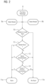
- FIG. 2 illustrates the flowchart for an exemplary embodiment of the method according to the invention.
- the method shown is carried out in the protection devices 2 ( 2 a , 2 b , 2 c ) shown in FIG. 1 .
- Each of the protection devices 2 compares all of its incoming data streams. For this purpose, two data streams, which can originate from different MUs, are always compared with one another at a certain time by the method according to the invention. This procedure is repeated until all data streams received by the respective protection device have been compared with one another.
- FIG. 2 therefore shows two data streams 9 a and 9 b , which originate from the MUs 4 a and 4 b .
- the procedure is carried out to decide whether the MUs 4 a and 4 b are synchronized with one another. If this is the case, the protection function of the protection devices 2 is continued; otherwise, it would have to be disabled.
- the protection devices 2 receive the pre-synchronization message 8 and two data streams 9 a and 9 b from the MUs 4 a and 4 b .
- the data telegrams of the data streams 9 a and 9 b contain information about the synchronization time source (global, local or IED-internal) and the identity of the grandmaster timer unit. This information is conveyed by the attributes “smpSynch” and “gmIdentity”.
- Pre-synchronization message 8 contains the statement indicating whether the present grandmaster timing unit was successfully synchronized with the previous grandmaster timing unit before the grandmaster role change.
- the pre-synchronization message also comprises the identity of the present grandmaster timing unit and the identity of the previous grandmaster timing unit.
- the first step 10 comprises testing whether the MUs 4 a and 4 b are globally or locally synchronized. If one MU were globally synchronized and the other were locally synchronized or at least one MU were synchronized in IED-internal fashion, then the MUs 4 a and 4 b would use different time bases. They would therefore not be synchronized with one another. This would correspond to the result 11 b “not synchronized”.
- the result 11 a of this test procedure is “synchronized”, in other words the data streams of the two MUs 4 a and 4 b are synchronized with one another. In order to be able to confirm that synchronization exists, however, further test steps must be carried out.
- Test step 12 comprises determining whether the MUs 4 a and 4 b are both globally synchronized. If this is the case, the MUs use the same global time base; the test finishes with the result 11 a “synchronized”. If the two data streams are not both globally synchronized, they must both be locally synchronized in view of the result of test step 10 .
- Test step 13 comprises testing whether the MUs 4 a and 4 b are synchronized with the same PTP grandmaster clock. If this is the case, the MUs use the same time base and are synchronized with one another. The result of the test is 11 a “synchronized”. However, if it is found that the MUs 4 a and 4 b are synchronized with different grandmaster timing units, another final test step must be performed.
- the fourth test step 14 comprises testing whether these different grandmaster timing units are the present and previous grandmaster timing units. If so, and pre-synchronization was successful, both use the same time base.
- the MUs 4 a and 4 b are synchronized with one another in this case.
- Test step 14 is performed using pre-synchronization message 8 .
- the two MUs 4 a and 4 b are synchronized with one another if, for example, the present grandmaster timing unit 3 c was synchronized with the previous grandmaster timing unit 3 a before the change of grandmaster role (pre-synchronization) and the two MUs 4 a and 4 b are synchronized with either the present or the previous grandmaster timing unit.
- the result is then 11 a “synchronized,” otherwise 11 b “not synchronized.”
- the test step 14 can thus reliably avoid a disablement of the protection function of the respective protection device, which would have occurred according to previously known methods.
Landscapes
- Engineering & Computer Science (AREA)
- Computer Networks & Wireless Communication (AREA)
- Signal Processing (AREA)
- Synchronisation In Digital Transmission Systems (AREA)
Abstract
Description
-
- assuming, by one of the timing units, an active grandmaster role as a synchronization source, while all other timing units remain in a slave state and synchronize with the one timing unit being the grandmaster timing unit having the active grandmaster role;
- when one of the other timing units changes from the slave state to the role of the grandmaster timing unit, notifying all IEDs in the local network via the local network, using a pre-synchronization message stating whether the presently active grandmaster timing unit was synchronized and, if applicable, with which previously active grandmaster timing unit the presently active grandmaster timing unit was synchronized, in order to avoid a function disablement of the IEDs that process data streams whose samples have been acquired in sync with the previously active grandmaster timing unit.
Claims (13)
Applications Claiming Priority (2)
| Application Number | Priority Date | Filing Date | Title |
|---|---|---|---|
| EP23190098.6 | 2023-08-07 | ||
| EP23190098.6A EP4507220A1 (en) | 2023-08-07 | 2023-08-07 | Method for preventing function blockade of intelligent electronic units (ieds) |
Publications (2)
| Publication Number | Publication Date |
|---|---|
| US20250055586A1 US20250055586A1 (en) | 2025-02-13 |
| US12328183B2 true US12328183B2 (en) | 2025-06-10 |
Family
ID=87557608
Family Applications (1)
| Application Number | Title | Priority Date | Filing Date |
|---|---|---|---|
| US18/796,558 Active US12328183B2 (en) | 2023-08-07 | 2024-08-07 | Method for avoiding function disablements for intelligent electronic units |
Country Status (3)
| Country | Link |
|---|---|
| US (1) | US12328183B2 (en) |
| EP (1) | EP4507220A1 (en) |
| CN (1) | CN119450677A (en) |
Citations (4)
| Publication number | Priority date | Publication date | Assignee | Title |
|---|---|---|---|---|
| US20040044799A1 (en) * | 2002-09-03 | 2004-03-04 | Nokia Corporation | Method, device and system for synchronizing of data providing for the handling of an interrupted synchronization process |
| US20120278421A1 (en) * | 2011-04-27 | 2012-11-01 | Centec Networks (Suzhou) Co., Ltd. | Providing a data sample in a measurement and control system |
| US20140281037A1 (en) | 2013-03-15 | 2014-09-18 | Broadcom Corporation | Fault Tolerant Clock Network |
| US20180109369A1 (en) | 2016-10-14 | 2018-04-19 | General Electric Technology Gmbh | Systems and methods for synchronizing time sources within a protection zone of a digital power substation |
-
2023
- 2023-08-07 EP EP23190098.6A patent/EP4507220A1/en active Pending
-
2024
- 2024-08-05 CN CN202411060782.8A patent/CN119450677A/en active Pending
- 2024-08-07 US US18/796,558 patent/US12328183B2/en active Active
Patent Citations (4)
| Publication number | Priority date | Publication date | Assignee | Title |
|---|---|---|---|---|
| US20040044799A1 (en) * | 2002-09-03 | 2004-03-04 | Nokia Corporation | Method, device and system for synchronizing of data providing for the handling of an interrupted synchronization process |
| US20120278421A1 (en) * | 2011-04-27 | 2012-11-01 | Centec Networks (Suzhou) Co., Ltd. | Providing a data sample in a measurement and control system |
| US20140281037A1 (en) | 2013-03-15 | 2014-09-18 | Broadcom Corporation | Fault Tolerant Clock Network |
| US20180109369A1 (en) | 2016-10-14 | 2018-04-19 | General Electric Technology Gmbh | Systems and methods for synchronizing time sources within a protection zone of a digital power substation |
Non-Patent Citations (4)
| Title |
|---|
| "IEEE Standard Profile for Use of IEEE 1588 Precision Time Protocol in Power System Applications; IEEE Std C37.238-2017 (Revision of IEEE Std C37.238-2011"; IEEE Standard; published: Jun. 17, 2017; pp. 1-42; XP068114900; DOI: 10.1109/IEEESTD.2017.7953616; ISBN: 978-1-5044-2326-7. |
| Brunner, Christoph et al.; "Smarter time sync: Applying the IEEE PC37.238 standard to power system applications"; Protective Relay Enginers; 2011 64th annual conference for; published: Apr. 11, 2011; pp. 91-102; XP031972549; DOI: 10.1109/CPRE.2011.6035608; ISBN: 978-1-4577-0494-9. |
| Spada, Eric et al.: "Time Sync—Redundant Grandmaster Clock Support"; Bd. 802.1; Nr. v1; published: May 14, 2013; pp. 1-10; XP068050436. |
| Whitehead, Michael et al.; "Validation Testing of IEC 61850 Process Bus Architecture in a Typical Digital Substation"; 2021 74th Conference for protective relay engineers; published: Mar. 22, 2021; pp. 1-9; XP033915260; DOI: 10.1109/CPRE48231.2021.9429718. |
Also Published As
| Publication number | Publication date |
|---|---|
| CN119450677A (en) | 2025-02-14 |
| EP4507220A1 (en) | 2025-02-12 |
| US20250055586A1 (en) | 2025-02-13 |
Similar Documents
| Publication | Publication Date | Title |
|---|---|---|
| US10859611B2 (en) | Measuring and mitigating channel delay in remote data acquisition | |
| CN103795143B (en) | Current differential protection | |
| Guo et al. | Design of a time synchronization system based on GPS and IEEE 1588 for transmission substations | |
| CA2771295C (en) | Line current differential protection upon loss of an external time reference | |
| EP2520040B1 (en) | Method and apparatus for detecting communication channel delay asymmetry | |
| CN106451763B (en) | A station-level bus network system of intelligent substation without global synchronization system | |
| EP2159940A1 (en) | Time synchronization in industrial process control or automation systems | |
| Castello et al. | A distributed PMU for electrical substations with wireless redundant process bus | |
| CN103513569A (en) | Method for synchronizing redundant time of intelligent substation | |
| US9614577B2 (en) | Clock synchronization for line differential protection | |
| CN107819537A (en) | It is a kind of based on synchronous closed loop monitoring electric substation automation system pair when method of calibration | |
| CN110620630B (en) | Time synchronization method, device, network equipment and computer readable storage medium | |
| EP4418602A1 (en) | Forwarding device and time synchronization system | |
| CN108762048A (en) | A method of realizing distribution terminal clock synchronization using power frequency current signal | |
| JP2018091828A (en) | System and method for time source synchronization within a protection zone of a digital power substation | |
| KR101698227B1 (en) | Apparatus for time synchronization of substation automation system | |
| Steinhauser et al. | IEEE 1588 for time synchronization of devices in the electric power industry | |
| US20150171621A1 (en) | Current differential relay | |
| US12328183B2 (en) | Method for avoiding function disablements for intelligent electronic units | |
| US11614767B2 (en) | Device and method for providing a clock signal to an application | |
| CN106647228B (en) | A fault judgment system for the master clock of a converter station | |
| Ingram et al. | Quantitative assessment of fault tolerant precision timing for electricity substations | |
| US20230077975A1 (en) | Time synchronization between ieds of different substations | |
| US10534090B2 (en) | Process bus-applied protection system | |
| CN120883542A (en) | Methods for synchronizing smart electronic devices in local restricted networks |
Legal Events
| Date | Code | Title | Description |
|---|---|---|---|
| FEPP | Fee payment procedure |
Free format text: ENTITY STATUS SET TO UNDISCOUNTED (ORIGINAL EVENT CODE: BIG.); ENTITY STATUS OF PATENT OWNER: LARGE ENTITY |
|
| STPP | Information on status: patent application and granting procedure in general |
Free format text: NOTICE OF ALLOWANCE MAILED -- APPLICATION RECEIVED IN OFFICE OF PUBLICATIONS |
|
| AS | Assignment |
Owner name: SIEMENS AKTIENGESELLSCHAFT, GERMANY Free format text: ASSIGNMENT OF ASSIGNORS INTEREST;ASSIGNOR:SIEMENS POWER AUTOMATION LTD.;REEL/FRAME:070472/0954 Effective date: 20250304 Owner name: SIEMENS POWER AUTOMATION LTD., CHINA Free format text: ASSIGNMENT OF ASSIGNORS INTEREST;ASSIGNOR:CHEN, JI;REEL/FRAME:070472/0951 Effective date: 20250304 Owner name: SIEMENS AKTIENGESELLSCHAFT, GERMANY Free format text: ASSIGNMENT OF ASSIGNORS INTEREST;ASSIGNORS:GOERBING, ANDREJ;FLEMMING, STEFAN;KOGAN, IGOR;AND OTHERS;SIGNING DATES FROM 20240903 TO 20240918;REEL/FRAME:070472/0944 |
|
| STCF | Information on status: patent grant |
Free format text: PATENTED CASE |