US12308775B2 - Motor drive device - Google Patents
Motor drive device Download PDFInfo
- Publication number
- US12308775B2 US12308775B2 US18/043,774 US202118043774A US12308775B2 US 12308775 B2 US12308775 B2 US 12308775B2 US 202118043774 A US202118043774 A US 202118043774A US 12308775 B2 US12308775 B2 US 12308775B2
- Authority
- US
- United States
- Prior art keywords
- motor
- cross point
- phase alternating
- current
- alternating current
- Prior art date
- Legal status (The legal status is an assumption and is not a legal conclusion. Google has not performed a legal analysis and makes no representation as to the accuracy of the status listed.)
- Active, expires
Links
Images


Classifications
-
- H—ELECTRICITY
- H02—GENERATION; CONVERSION OR DISTRIBUTION OF ELECTRIC POWER
- H02P—CONTROL OR REGULATION OF ELECTRIC MOTORS, ELECTRIC GENERATORS OR DYNAMO-ELECTRIC CONVERTERS; CONTROLLING TRANSFORMERS, REACTORS OR CHOKE COILS
- H02P29/00—Arrangements for regulating or controlling electric motors, appropriate for both AC and DC motors
- H02P29/02—Providing protection against overload without automatic interruption of supply
- H02P29/024—Detecting a fault condition, e.g. short circuit, locked rotor, open circuit or loss of load
- H02P29/0243—Detecting a fault condition, e.g. short circuit, locked rotor, open circuit or loss of load the fault being a broken phase
-
- H—ELECTRICITY
- H02—GENERATION; CONVERSION OR DISTRIBUTION OF ELECTRIC POWER
- H02P—CONTROL OR REGULATION OF ELECTRIC MOTORS, ELECTRIC GENERATORS OR DYNAMO-ELECTRIC CONVERTERS; CONTROLLING TRANSFORMERS, REACTORS OR CHOKE COILS
- H02P27/00—Arrangements or methods for the control of AC motors characterised by the kind of supply voltage
- H02P27/04—Arrangements or methods for the control of AC motors characterised by the kind of supply voltage using variable-frequency supply voltage, e.g. inverter or converter supply voltage
- H02P27/06—Arrangements or methods for the control of AC motors characterised by the kind of supply voltage using variable-frequency supply voltage, e.g. inverter or converter supply voltage using DC to AC converters or inverters
-
- H—ELECTRICITY
- H02—GENERATION; CONVERSION OR DISTRIBUTION OF ELECTRIC POWER
- H02H—EMERGENCY PROTECTIVE CIRCUIT ARRANGEMENTS
- H02H7/00—Emergency protective circuit arrangements specially adapted for specific types of electric machines or apparatus or for sectionalised protection of cable or line systems, and effecting automatic switching in the event of an undesired change from normal working conditions
- H02H7/08—Emergency protective circuit arrangements specially adapted for specific types of electric machines or apparatus or for sectionalised protection of cable or line systems, and effecting automatic switching in the event of an undesired change from normal working conditions for dynamo-electric motors
- H02H7/09—Emergency protective circuit arrangements specially adapted for specific types of electric machines or apparatus or for sectionalised protection of cable or line systems, and effecting automatic switching in the event of an undesired change from normal working conditions for dynamo-electric motors against over-voltage; against reduction of voltage; against phase interruption
-
- H—ELECTRICITY
- H02—GENERATION; CONVERSION OR DISTRIBUTION OF ELECTRIC POWER
- H02P—CONTROL OR REGULATION OF ELECTRIC MOTORS, ELECTRIC GENERATORS OR DYNAMO-ELECTRIC CONVERTERS; CONTROLLING TRANSFORMERS, REACTORS OR CHOKE COILS
- H02P21/00—Arrangements or methods for the control of electric machines by vector control, e.g. by control of field orientation
- H02P21/22—Current control, e.g. using a current control loop
Definitions
- the present disclosure relates to a motor drive device that drives a motor.
- the motor drive device may not be able to normally drive the motor.
- an object of the present disclosure is to provide a motor drive device capable of outputting a control signal not to drive a motor in a case where there is a possibility that the motor cannot be normally driven due to a phase loss in a three-phase alternating current serving as a power source.
- a motor drive device is a motor drive device that drives a motor using a three-phase alternating current as a power source.
- the motor drive device includes a rectifier circuit that rectifies the three-phase alternating current to generate a direct current, a current detection circuit that detects the direct current rectified by the rectifier current, and a cross point detection circuit that detects a cross point between the direct current detected by the current detection circuit and a predetermined current value, and outputs a control signal indicating whether or not to drive the motor based on a result of the detection.
- the motor drive device capable of outputting the control signal not to drive the motor is provided.
- FIG. 1 is a block diagram illustrating a configuration of a motor drive system according to a first exemplary embodiment.
- FIG. 2 A is a waveform diagram illustrating a voltage waveform in a low load state in a case where there is no phase loss in a three-phase alternating current.
- FIG. 2 B is a waveform diagram illustrating a voltage waveform in a high load state in a case where there is no phase loss in the three-phase alternating current.
- FIG. 2 C is a waveform diagram illustrating a voltage waveform in a low load state in a case where there is a phase loss in the three-phase alternating current.
- FIG. 2 D is a waveform diagram illustrating a voltage waveform in a high load state in a case where there is a phase loss in the three-phase alternating current.
- FIG. 3 A is a waveform diagram illustrating a current waveform and the number of times of detection of a cross point in a low load state in a case where there is no phase loss in the three-phase alternating current.
- FIG. 3 B is a waveform diagram illustrating a current waveform and the number of times of detection of a cross point in a high load state in a case where there is no phase loss in the three-phase alternating current.
- FIG. 3 C is a waveform diagram illustrating a current waveform and the number of times of detection of a cross point in a low load state in a case where there is a phase loss in the three-phase alternating current.
- FIG. 3 D is a waveform diagram illustrating a current waveform and the number of times of detection of a cross point in a high load state in a case where there is a phase loss in a three-phase alternating current.
- FIG. 4 is a flowchart illustrating motor stop processing.
- FIG. 5 is a block diagram illustrating a configuration of a motor drive system according to a second exemplary embodiment.
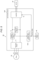
- FIG. 6 is a block diagram illustrating a configuration of a motor drive system according to a third exemplary embodiment.
- CD-ROM compact disk read only memory
- FIG. 1 is a block diagram illustrating a configuration of motor drive system 1 according to a first exemplary embodiment.
- motor drive system 1 includes motor drive device 10 , three-phase alternating current power supply 20 , motor 30 , and display device 40 .
- Motor 30 is driven by motor drive device 10 .
- Display device 40 displays an image based on a control signal (to be described later) output from motor drive device 10 .
- Motor drive device 10 uses, as a power source, the three-phase alternating current supplied from three-phase alternating current power supply 20 to drive motor 30 .
- motor drive device 10 includes rectifier circuit 11 , current detection circuit 12 , cross point detection circuit 13 , inverter 14 , and smoothing circuit 15 .
- Rectifier circuit 11 rectifies the three-phase alternating current supplied from three-phase alternating current power supply 20 .
- a direct current rectified by rectifier circuit 11 and not smoothed by smoothing circuit 15 to be described below is also referred to as an “unsmoothed direct current”.
- the unsmoothed direct current rectified by rectifier circuit 11 is supplied to smoothing circuit 15 , and the supplied unsmoothed direct current is smoothed.
- the direct current smoothed by smoothing circuit 15 is also referred to as a “smoothed direct current”.
- the smoothed direct current smoothed by smoothing circuit 15 is supplied to inverter 14 to drive motor 30 . More specifically, inverter 14 converts the supplied smoothed direct current into a three-phase alternating current, and supplies the converted three-phase alternating current to motor 30 to drive motor 30 .
- inverter 14 stops the conversion into the three-phase alternating current.
- inverter 14 starts the conversion into the three-phase alternating current.
- FIG. 2 A is a waveform diagram illustrating a voltage waveform in a low load state in a case where there is no phase loss in the three-phase alternating current.
- FIG. 2 B is a waveform diagram illustrating a voltage waveform in a high load state in a case where there is no phase loss in the three-phase alternating current.
- FIG. 2 A is a waveform diagram in a state (hereinafter, also referred to as a “low load state”) where a relatively small load with which a voltage drop does not occur is applied to motor 30 only until a voltage of the smoothed direct current is greater than or equal to a minimum voltage of the unsmoothed direct current in a case where there is no phase loss in the three-phase alternating current input to rectifier circuit 11 .
- a low load state a state where a relatively small load with which a voltage drop does not occur is applied to motor 30 only until a voltage of the smoothed direct current is greater than or equal to a minimum voltage of the unsmoothed direct current in a case where there is no phase loss in the three-phase alternating current input to rectifier circuit 11 .
- 2 B is a waveform diagram in a state (hereinafter, also referred to as a “high load state”) where a relatively large load with which a voltage drop occurs is applied to motor 30 until the voltage of the smoothed direct current is less than the minimum voltage of the unsmoothed direct current in a case where there is no phase loss in the three-phase alternating current input to rectifier circuit 11 .
- FIG. 2 C is a waveform diagram illustrating a voltage waveform in a low load state in a case where there is a phase loss in the three-phase alternating current.
- FIG. 2 D is a waveform diagram illustrating a voltage waveform in a high load state in a case where there is a phase loss in the three-phase alternating current.
- a vertical axis represents a voltage
- a horizontal axis represents a time
- L1-L2, L2-L3, and L3-L1 are a voltage difference between the L1 phase and the L2 phase, a voltage difference between the L2 phase and the L3 phase, and a voltage difference between the L3 phase and the L1 phase, respectively.
- Vrec is a voltage of the unsmoothed direct current rectified by rectifier circuit 11 .
- Vpn is a voltage of the smoothed direct current smoothed by smoothing circuit 15 .
- motor drive device 10 Referring back to FIG. 1 , the description of motor drive device 10 will be continued.
- Current detection circuit 12 detects a current of the unsmoothed direct current rectified by rectifier circuit 11 .
- Cross point detection circuit 13 detects a cross point between the current detected by current detection circuit 12 and a predetermined current value (here, the predetermined current value is set to 0 [A].).
- the cross point refers to a state where the current detected by current detection circuit 12 and the predetermined current value have the same value.
- cross point detection circuit 13 detects the cross point by detecting a change point at which the current detected by current detection circuit 12 changes from a state of the predetermined current value or less to a state of the predetermined current value or more.
- cross point detection circuit 13 outputs a drive signal indicating whether or not to drive motor 30 based on a detection result of the cross point. More specifically, cross point detection circuit 13 outputs (1) a control signal indicating that the motor 30 is not to be driven in a case where the number of times of detection of the cross point detected in one cycle of the three-phase alternating current input to rectifier circuit 11 is 2, and outputs (2) a control signal indicating that the motor 30 is to be driven in a case where the number of times of detection of the cross point detected in one cycle of the three-phase alternating current input to rectifier circuit 11 is 0 or 6.
- cross point detection circuit 13 outputs the drive signal in this manner is that the number of times of detection of the cross point detected in one cycle of the three-phase alternating current input to rectifier circuit 11 , which is detected by cross point detection circuit 13 , is 2 in a case where there is a phase loss in the three-phase alternating current input to rectifier circuit 11 , and the number of times of detection of the cross point detected in one cycle of the three-phase alternating current input to rectifier circuit 11 , which is detected by cross point detection circuit 13 , in a case where there is no phase loss in the three-phase alternating current input to rectifier circuit 11 , is 0 or 6.
- cross point detection circuit 13 outputs a control signal indicating that the motor 30 is not to be driven to rectifier circuit 11 in a case where there is a phase loss in the three-phase alternating current input, and outputs a control signal indicating that the motor 30 is to be driven to rectifier circuit 11 in a case where there is no phase loss in the three-phase alternating current input.
- FIG. 3 A is a waveform diagram illustrating a current waveform and the number of times of detection of a cross point in a low load state in a case where there is no phase loss in the three-phase alternating current.
- FIG. 3 B is a waveform diagram illustrating a current waveform and the number of times of detection of a cross point in a high load state in a case where there is no phase loss in the three-phase alternating current.
- FIG. 3 C is a waveform diagram illustrating a current waveform and the number of times of detection of a cross point in a low load state in a case where there is a phase loss in the three-phase alternating current.
- FIG. 3 D is a waveform diagram illustrating a current waveform and the number of times of detection of a cross point in a high load state in a case where there is a phase loss in the three-phase alternating current.
- cross point detection circuit 13 constantly detects the cross point 0 times or 6 times in one cycle of the three-phase alternating current input to rectifier circuit 11 .
- the motor stop processing is processing of stopping the drive of motor 30 when the phase loss occurs in the three-phase alternating current supplied from three-phase alternating current power supply 20 in a case where motor drive device 10 drives motor 30 .
- Motor drive device 10 starts driving motor 30 , and thus, the motor stop processing is started, for example.
- FIG. 4 is a flowchart illustrating the motor stop processing.
- cross point detection circuit 13 checks whether the number of times of detection of the cross point detected in one cycle of the three-phase alternating current input to rectifier circuit 11 is 2 (step S 10 ).
- step S 10 in a case where the number of times of detection of the cross point is not 2 (No in step S 10 ), cross point detection circuit 13 returns to the processing of step S 10 again and repeats the processing of step S 10 .
- cross point detection circuit 13 In the processing of step S 10 , in a case where the number of times of detection of the cross point to be detected is 2 (Yes in step S 10 ), cross point detection circuit 13 outputs a control signal not to drive motor 30 (step S 20 ).
- inverter 14 stops the conversion of the smoothed direct current into the three-phase alternating current supplied to motor 30 (step S 30 ).
- step S 40 When the conversion into the three-phase alternating current supplied to motor 30 is stopped, motor 30 is stopped (step S 40 ).
- step S 50 When the control signal indicating that the motor 30 is not to be driven motor 30 is output, since there is a phase loss in the three-phase alternating current input to rectifier circuit 11 , the display device 40 displays that motor 30 is stopped (step S 50 ).
- step S 50 motor drive system 1 ends the motor stop processing.
- motor drive device 10 outputs the control signal indicating that the motor 30 is not to be driven.
- the control signal indicating that the motor 30 is not to be driven can be output.
- motor drive device 10 in the motor drive device according to the second exemplary embodiment, components similar to the components of motor drive device 10 will be denoted by the same reference marks as those already described, detailed description thereof will be omitted, and differences from motor drive device 10 will be mainly described,
- FIG. 5 is a block diagram illustrating a configuration of motor drive system 1 A according to the second exemplary embodiment.
- motor drive system 1 A is configured such that motor drive device 10 of motor drive system 1 according to the first exemplary embodiment is changed to motor drive device 10 A.
- Motor drive device 10 A is configured such that cross point detection circuit 13 of motor drive device 10 is changed to cross point detection circuit 13 A.
- Cross point detection circuit 13 has a configuration in which a predetermined current value is set to 0 [A].
- cross point detection circuit 13 A has a configuration in which a predetermined current value is set to a positive value X [A].
- predetermined current value X [A] which is a positive value is a maximum value of the current flowing from rectifier circuit 11 to smoothing circuit 15 in a case where a load with which motor 30 can be normally driven is applied to motor 30 even though there is a phase loss in the three-phase alternating current input to rectifier circuit 11 .
- cross point detection circuit 13 A having the above configuration, even in a case where there is a phase loss in the three-phase alternating current input to rectifier circuit 11 , when a load with which motor 30 can be normally driven is applied to motor 30 , the number of times of detection of the cross point detected in one cycle of the three-phase alternating current input to rectifier circuit 11 is 0.
- cross point detection circuit 13 A having the above configuration, in a case where there is a phase loss in the three-phase alternating current input to rectifier circuit 11 , when a load greater than or equal to a load with which motor 30 can be normally driven is applied to motor 30 , similarly to cross point detection circuit 13 according to the first exemplary embodiment, the number of times of detection of the cross point to be detected in one cycle of the three-phase alternating current input to rectifier circuit 11 is 2.
- cross point detection circuit 13 A having the above configuration, in a case where there is no phase loss in the three-phase alternating current input to rectifier circuit 11 , similarly to cross point detection circuit 13 according to the first exemplary embodiment, the number of times of detection of the cross point detected in one cycle of the three-phase alternating current input to rectifier circuit 11 is 0 or 6.
- cross point detection circuit 13 A outputs a control signal to drive motor 30 when the load applied to motor 30 is a load with which motor 30 can be normally driven, and outputs a control signal not to drive motor 30 when there is a phase loss in the three-phase alternating current input to rectifier circuit 11 and the load applied to motor 30 is a load greater than or equal to the load with which motor 30 can be normally driven.
- motor drive device 10 A In addition to a case where there is no phase loss in the three-phase alternating current input to rectifier circuit 11 , even in a case where there is a phase loss in the three-phase alternating current input to rectifier circuit 11 , motor drive device 10 A having the above configuration outputs a control signal indicating that the motor 30 is to be driven when the load applied to motor 30 is small enough to normally drive motor 30 . On the other hand, in a case where there is a phase loss in the three-phase alternating current input to rectifier circuit 11 , when the load applied to motor 30 is a load greater than or equal to a load with which drive motor 30 can be normally driven, motor drive device 10 A outputs a control signal indicating that the motor 30 is not to be driven.
- motor drive device 10 A having the above configuration, in a case where there is a possibility that motor 30 cannot be normally driven due to a phase loss in the three-phase alternating current serving as the power source, it is possible to output the control signal indicating that the motor 30 is not to be driven.
- motor drive device 10 in the motor drive device according to the third exemplary embodiment, components similar to the components of motor drive device 10 will be denoted by the same reference marks as those already described, detailed description thereof will be omitted, and differences from motor drive device 10 will be mainly described.
- FIG. 6 is a block diagram illustrating a configuration of motor drive system 1 B according to the third exemplary embodiment.
- motor drive system 1 B is configured such that motor drive device 10 of motor drive device 10 according to the first exemplary embodiment is changed to motor drive device 10 B.
- motor drive device 10 is configured such that voltage detection circuit 16 and power calculation circuit 17 are added to motor drive device 10 and cross point detection circuit 13 is changed to cross point detection circuit 13 B.
- Voltage detection circuit 16 detects the voltage of the smoothed direct current smoothed by smoothing circuit 15 .
- Power calculation circuit 17 calculates a power for driving motor 30 based on the current detected by current detection circuit 12 and the voltage detected by voltage detection circuit 16 .
- power calculation circuit 17 In a case where the calculated power is smaller than a predetermined power value, power calculation circuit 17 outputs a first signal indicating that the calculated power is smaller than the predetermined power value.
- the predetermined power value is a maximum value of the power for driving motor 30 in a case where the load applied to motor 30 is a load with which motor 30 can be normally driven.
- cross point detection circuit 13 B detects a cross point between the current detected by current detection circuit 12 and a predetermined current value (here, the predetermined current value is set to 0 [A].).
- Cross point detection circuit 13 D outputs a drive signal indicating whether or not to drive motor 30 based on a detection result of the cross point. More specifically, cross point detection circuit 13 D outputs (1) a control signal indicating that the motor 30 is not to be driven when the first signal is not output from power calculation circuit 17 in a case where the number of times of detection of the cross point detected in one cycle of the three-phase alternating current input to rectifier circuit 11 is 2, and outputs (2) a control signal indicating that the motor 30 is to be driven when the first signal is output from power calculation circuit 17 in a case where the number of times of detection of the cross point detected in one cycle of the three-phase alternating current input to rectifier circuit 11 is 0 or 6 and in a case where the number of times of detection of the cross point detected in one cycle of the three-phase alternating current input to rectifier circuit 11 is 2.
- cross point detection circuit 13 B outputs a control signal indicating that the motor 30 is not to be driven when the load applied to motor 30 is a load greater than or equal to a load with which motor 30 can be normally driven in a case where there is a phase loss in the three-phase alternating current input to rectifier circuit 11 , and outputs a control signal indicating that the motor 30 is to be driven when the load applied to motor 30 is a load with which motor 30 can be normally driven in a case where there is no phase loss in the three-phase alternating current input to rectifier circuit 11 and in a case where there is a phase loss in the three-phase alternating current input to rectifier circuit 11 .
- motor drive device 10 B having the above configuration suppresses the output of the control signal indicating that the motor 30 is not to be driven and instead outputs the control signal indicating that the motor 30 is to be driven.
- motor drive device 10 B when there is a phase loss in the three-phase alternating current input to rectifier circuit 11 and the load applied to motor 30 is a load greater than or equal to a load with which motor 30 can be normally driven, motor drive device 10 B outputs a control signal indicating that the motor 30 is not to be driven.
- motor drive device 10 B having the above configuration, in a case where there is a possibility that motor 30 cannot be normally driven due to a phase loss in the three-phase alternating current serving as the power source, it is possible to output the control signal indicating that the motor 30 is not to be driven.
- the motor drive device has been described above based on the first to third exemplary embodiments.
- the present disclosure is not limited to these exemplary embodiments. Configurations in which various modifications conceived by those skilled in the art are applied to these exemplary embodiments, and configurations established by combining structural elements in different exemplary embodiments may also fall within the scope of one or more aspects, without departing from the scope of the present disclosure.
- cross point detection circuit 13 may count the number of times of detection of the cross point detected in one cycle of the three-phase alternating current input to rectifier circuit 11 every one cycle, or may count an average value of a plurality of cycles.
- predetermined current value X [A] set in cross point detection circuit 13 A is the maximum value of the current flowing from rectifier circuit 11 to smoothing circuit 15 in a case where the load applied to motor 30 is a load with which motor 30 can be normally driven even though there is a phase loss in the three-phase alternating current input to rectifier circuit 11 .
- a positive value smaller than the maximum value may be used. In the case of this configuration, in a case where there is a phase loss in the three-phase alternating current input to rectifier circuit 11 , when a control signal indicating that the motor 30 is to be driven is output from cross point detection circuit 13 A, the load applied to motor 30 is a load with which motor 30 can be normally driven.
- the predetermined power value set in power calculation circuit 17 is the maximum value of the power for driving motor 30 in a case where the load applied to motor 30 is a load with which motor 30 can be normally driven even though there is a phase loss in the three-phase alternating current input to rectifier circuit 11 .
- a value smaller than the maximum value may be used. In the case of this configuration, in a case where there is a phase loss in the three-phase alternating current input to rectifier circuit 11 , when a control signal indicating that the motor 30 is to be driven is output from cross point detection circuit 13 B, the load applied to motor 30 is a load with which motor 30 can be normally driven.
- voltage detection circuit 16 is configured to detect the voltage of the smoothed direct current smoothed by smoothing circuit 15 .
- voltage detection circuit 16 may be configured to detect the voltage of the unsmoothed direct current before being smoothed by smoothing circuit 15 .
- a motor drive device is a motor drive device that drives a motor using a three-phase alternating current as a power source.
- the motor drive device includes a rectifier circuit that rectifies the three-phase alternating current to generate a direct current, a current detection circuit that detects the direct current rectified by the rectifier circuit, and a cross point detection circuit that detects a cross point between the direct current detected by the current detection circuit and a predetermined current value, and outputs a control signal indicating whether or not to drive the motor based on a result of the detection.
- the predetermined current value is set to an appropriate value, and thus, a detection frequency of the cross point can be set to be different between a case where there is a possibility that the motor cannot be norm ally driven due to a phase loss in the three-phase alternating current serving as the power source and a case where there is no possibility that the motor cannot be normally driven.
- a detection frequency of the cross point can be set to be different between a case where there is a possibility that the motor cannot be norm ally driven due to a phase loss in the three-phase alternating current serving as the power source and a case where there is no possibility that the motor cannot be normally driven.
- the cross point detection circuit may output the control signal indicating that the motor is not to be drive the motor in a case where the number of times of detection of the cross point detected in one cycle of the three-phase alternating current is 2.
- the predetermined current value may be zero, and the cross point detection circuit may further output a control signal indicating that the motor 30 is to be driven in a case where the number of times of the cross point detected in one cycle of the three-phase alternating current is 0 or 6.
- a control signal to drive the motor can be output.
- the predetermined current value may be a positive value, and the cross point detection circuit may further output a control signal indicating that the motor 30 is to be driven in a case where the number of times of the detection of the cross point in one cycle of the three-phase alternating current is 0.
- the predetermined current value is set to an appropriate value, and thus, it is possible to output a control signal indicating that the motor is to be driven when the load applied to the motor is small enough to normally drive the motor even in a case where there is a phase loss in the three-phase alternating current.
- the motor control device may further include a power calculation circuit that calculates a power for driving the motor, and in a case where the power calculated by the power calculation circuit is smaller than a predetermined power value, the cross point detection circuit may suppress the output of the control signal indicating that the motor is not to be driven.
- the predetermined power value is set to an appropriate value, and thus, it is possible to suppress the output of the control signal indicating that the motor 30 is not to be driven when the load applied to the motor is small enough to normally drive the motor even though there is a phase loss in the three-phase alternating current.
- the motor control device may further include a smoothing circuit that smooths a direct current generated by the rectifier circuit, and an inverter to which the direct current smoothed by the smoothing circuit is supplied to drive the motor.
- the current detection circuit may detect the current value by using the direct current generated by the rectifier circuit before being smoothed by the smoothing circuit.
- the direct current supplied to the inverter can be a smoothed direct current.
- the present disclosure is widely applicable to a motor drive device that drives a motor.
Landscapes
- Engineering & Computer Science (AREA)
- Power Engineering (AREA)
- Control Of Ac Motors In General (AREA)
- Emergency Protection Circuit Devices (AREA)
Abstract
Description
-
- 1: Unexamined Japanese Patent Publication No. 2000-116186
-
- three-phase alternating
current power supply 20 supplies a three-phase alternating current including three phases of an L1 phase, an L2 phase, and an L3 phase tomotor drive device 10.
- three-phase alternating
-
- 1, 1A, 1B: motor drive system
- 10, 10A, 10B: motor drive device
- 11: rectifier circuit
- 12: current detection circuit
- 13, 13A, 13B: cross point detection circuit
- 14: inverter
- 15: smoothing circuit
- 16: voltage detection circuit
- 17: power calculation circuit
- 20: three-phase alternating current power supply
- 30: motor
- 40: display device
Claims (4)
Applications Claiming Priority (3)
| Application Number | Priority Date | Filing Date | Title |
|---|---|---|---|
| JP2020159133 | 2020-09-23 | ||
| JP2020-159133 | 2020-09-23 | ||
| PCT/JP2021/028260 WO2022064840A1 (en) | 2020-09-23 | 2021-07-30 | Motor drive device |
Publications (2)
| Publication Number | Publication Date |
|---|---|
| US20230336103A1 US20230336103A1 (en) | 2023-10-19 |
| US12308775B2 true US12308775B2 (en) | 2025-05-20 |
Family
ID=80845272
Family Applications (1)
| Application Number | Title | Priority Date | Filing Date |
|---|---|---|---|
| US18/043,774 Active 2041-12-17 US12308775B2 (en) | 2020-09-23 | 2021-07-30 | Motor drive device |
Country Status (6)
| Country | Link |
|---|---|
| US (1) | US12308775B2 (en) |
| EP (1) | EP4220939B1 (en) |
| JP (1) | JP7731038B2 (en) |
| CN (1) | CN116325480A (en) |
| TW (1) | TWI899320B (en) |
| WO (1) | WO2022064840A1 (en) |
Citations (11)
| Publication number | Priority date | Publication date | Assignee | Title |
|---|---|---|---|---|
| JPH03207274A (en) | 1990-01-08 | 1991-09-10 | Hitachi Ltd | Abnormality detection device for inverter equipment |
| JPH08223930A (en) | 1995-02-08 | 1996-08-30 | Mitsubishi Electric Corp | Control device for air conditioner |
| JPH09284985A (en) | 1996-04-09 | 1997-10-31 | Daikin Ind Ltd | Power supply device for air conditioner |
| JP2000116186A (en) | 1998-09-30 | 2000-04-21 | Matsushita Electric Ind Co Ltd | AC servo motor control device and open phase detection circuit |
| CN1455263A (en) | 2003-01-17 | 2003-11-12 | 艾默生网络能源有限公司 | Open-phase detecting method and open-phase detecting circuit applying for three-phase four-line input equipment |
| JP2006296168A (en) | 2005-04-14 | 2006-10-26 | Yaskawa Electric Corp | Power converter and its power failure determination method |
| JP2008223930A (en) | 2007-03-14 | 2008-09-25 | Bridgestone Corp | Torsional damper |
| JP2009284985A (en) | 2008-05-27 | 2009-12-10 | Panasonic Electric Works Co Ltd | Dental bleaching mouthpiece and its manufacturing method |
| US20150365020A1 (en) * | 2013-02-14 | 2015-12-17 | Toshiba Mitsubishi-Electric Industrial Systems Corporation | Thyristor starting device and control method therefor |
| EP3502723A1 (en) | 2017-12-18 | 2019-06-26 | Mitsubishi Heavy Industries Thermal Systems, Ltd. | Program, system and method for determination of phase loss alternating power supply |
| US20230261601A1 (en) * | 2020-10-19 | 2023-08-17 | Daikin Industries, Ltd. | Power conversion system |
Family Cites Families (13)
| Publication number | Priority date | Publication date | Assignee | Title |
|---|---|---|---|---|
| JP2003148783A (en) | 2002-08-05 | 2003-05-21 | Yanmar Co Ltd | Engine heat pump |
| TWI297564B (en) * | 2002-08-26 | 2008-06-01 | Int Rectifier Corp | Input filter and motor drive system |
| JP4804100B2 (en) * | 2005-10-18 | 2011-10-26 | 三洋電機株式会社 | Motor drive device, control method therefor, and air conditioner |
| JP2012005257A (en) * | 2010-06-17 | 2012-01-05 | Fuji Electric Co Ltd | Defective phase detector of three-phase inverter |
| JP2013143879A (en) * | 2012-01-12 | 2013-07-22 | Panasonic Corp | Inverter control device |
| WO2015033427A1 (en) * | 2013-09-05 | 2015-03-12 | 三菱電機株式会社 | Air conditioning device |
| JP2015201905A (en) * | 2014-04-04 | 2015-11-12 | パナソニックIpマネジメント株式会社 | Inverter control device |
| KR102314037B1 (en) * | 2014-06-09 | 2021-10-15 | 엘지전자 주식회사 | Mootor driver and air conditioner including the same |
| CN106208865B (en) * | 2016-08-10 | 2018-09-18 | 天津工业大学 | More permanent magnet synchronous motor Virtual-shaft control methods based on Load Torque Observer |
| CN107425765A (en) * | 2017-07-28 | 2017-12-01 | 无锡双能达科技有限公司 | A kind of DC brushless motor controller and its control method based on position-sensor-free |
| CN107800347B (en) * | 2017-11-22 | 2020-09-01 | 广东美的制冷设备有限公司 | AC motor control method, AC motor control circuit, and air conditioner |
| JP2019140778A (en) * | 2018-02-08 | 2019-08-22 | パナソニックIpマネジメント株式会社 | Motor control device, open-phase detection device, and open-phase detection method for motor control device |
| CN111665400A (en) * | 2019-03-07 | 2020-09-15 | 丹佛斯(天津)有限公司 | Phase loss detection device, compressor comprising same and phase loss detection method |
-
2021
- 2021-07-30 WO PCT/JP2021/028260 patent/WO2022064840A1/en not_active Ceased
- 2021-07-30 EP EP21871972.2A patent/EP4220939B1/en active Active
- 2021-07-30 CN CN202180063256.5A patent/CN116325480A/en active Pending
- 2021-07-30 JP JP2022551168A patent/JP7731038B2/en active Active
- 2021-07-30 US US18/043,774 patent/US12308775B2/en active Active
- 2021-09-01 TW TW110132494A patent/TWI899320B/en active
Patent Citations (11)
| Publication number | Priority date | Publication date | Assignee | Title |
|---|---|---|---|---|
| JPH03207274A (en) | 1990-01-08 | 1991-09-10 | Hitachi Ltd | Abnormality detection device for inverter equipment |
| JPH08223930A (en) | 1995-02-08 | 1996-08-30 | Mitsubishi Electric Corp | Control device for air conditioner |
| JPH09284985A (en) | 1996-04-09 | 1997-10-31 | Daikin Ind Ltd | Power supply device for air conditioner |
| JP2000116186A (en) | 1998-09-30 | 2000-04-21 | Matsushita Electric Ind Co Ltd | AC servo motor control device and open phase detection circuit |
| CN1455263A (en) | 2003-01-17 | 2003-11-12 | 艾默生网络能源有限公司 | Open-phase detecting method and open-phase detecting circuit applying for three-phase four-line input equipment |
| JP2006296168A (en) | 2005-04-14 | 2006-10-26 | Yaskawa Electric Corp | Power converter and its power failure determination method |
| JP2008223930A (en) | 2007-03-14 | 2008-09-25 | Bridgestone Corp | Torsional damper |
| JP2009284985A (en) | 2008-05-27 | 2009-12-10 | Panasonic Electric Works Co Ltd | Dental bleaching mouthpiece and its manufacturing method |
| US20150365020A1 (en) * | 2013-02-14 | 2015-12-17 | Toshiba Mitsubishi-Electric Industrial Systems Corporation | Thyristor starting device and control method therefor |
| EP3502723A1 (en) | 2017-12-18 | 2019-06-26 | Mitsubishi Heavy Industries Thermal Systems, Ltd. | Program, system and method for determination of phase loss alternating power supply |
| US20230261601A1 (en) * | 2020-10-19 | 2023-08-17 | Daikin Industries, Ltd. | Power conversion system |
Non-Patent Citations (2)
| Title |
|---|
| International Search Report of PCT application No. PCT/JP2021/028260 dated Sep. 28, 2021. |
| The EPC Office Action dated Jan. 31, 2024 for the related European Patent Application No. 21871972.2. |
Also Published As
| Publication number | Publication date |
|---|---|
| EP4220939B1 (en) | 2025-06-04 |
| TW202215768A (en) | 2022-04-16 |
| US20230336103A1 (en) | 2023-10-19 |
| WO2022064840A1 (en) | 2022-03-31 |
| CN116325480A (en) | 2023-06-23 |
| EP4220939A4 (en) | 2024-02-28 |
| EP4220939A1 (en) | 2023-08-02 |
| JPWO2022064840A1 (en) | 2022-03-31 |
| JP7731038B2 (en) | 2025-08-29 |
| TWI899320B (en) | 2025-10-01 |
Similar Documents
| Publication | Publication Date | Title |
|---|---|---|
| CN100446407C (en) | Method of controlling motor drive speed | |
| JP5274236B2 (en) | Three-phase inverter power circuit protection device | |
| US8030878B2 (en) | Motor driving device having power failure detection function | |
| US9124210B2 (en) | Motor control apparatus with power failure determination unit | |
| EP2892146A2 (en) | Motor control system, control device, and control method | |
| JPH07227086A (en) | Inverter failure detection method | |
| US20090052209A1 (en) | Inverter Device | |
| WO2017154334A1 (en) | Inverter device | |
| JP2016158323A (en) | Harmonic restraint device with active filter | |
| JP6895921B2 (en) | Power converter and abnormality detection method | |
| US11128252B2 (en) | Motor drive device | |
| WO2016121113A1 (en) | Inverter device | |
| US12308775B2 (en) | Motor drive device | |
| JP2002238299A (en) | Inverter failure detection method | |
| EP3229367B1 (en) | Power converter and control method of power converter | |
| US20200161988A1 (en) | Power conversion apparatus | |
| JP2008043057A (en) | PWM converter | |
| JP2012042316A (en) | Inverter device | |
| EP3057222B1 (en) | Rectifying device and motor driving device | |
| US11817774B2 (en) | Control device for power converter | |
| KR20180101837A (en) | Apparatus for controlling inverter | |
| JPWO2022064840A5 (en) | ||
| JP6012453B2 (en) | PWM converter device and elevator device | |
| JP2009147993A (en) | Inverter control device, motor drive device, and air conditioner | |
| JP4804290B2 (en) | Method for determining abnormality of current detection means, control device for three-phase AC motor using the method, and electric vehicle control system using the device |
Legal Events
| Date | Code | Title | Description |
|---|---|---|---|
| FEPP | Fee payment procedure |
Free format text: ENTITY STATUS SET TO UNDISCOUNTED (ORIGINAL EVENT CODE: BIG.); ENTITY STATUS OF PATENT OWNER: LARGE ENTITY |
|
| AS | Assignment |
Owner name: PANASONIC INTELLECTUAL PROPERTY MANAGEMENT CO., LTD., JAPAN Free format text: ASSIGNMENT OF ASSIGNORS INTEREST;ASSIGNOR:FURUKAWA, SATOSHI;REEL/FRAME:064349/0554 Effective date: 20221202 |
|
| STPP | Information on status: patent application and granting procedure in general |
Free format text: DOCKETED NEW CASE - READY FOR EXAMINATION |
|
| STPP | Information on status: patent application and granting procedure in general |
Free format text: NON FINAL ACTION MAILED |
|
| STPP | Information on status: patent application and granting procedure in general |
Free format text: RESPONSE TO NON-FINAL OFFICE ACTION ENTERED AND FORWARDED TO EXAMINER |
|
| STPP | Information on status: patent application and granting procedure in general |
Free format text: FINAL REJECTION MAILED |
|
| STPP | Information on status: patent application and granting procedure in general |
Free format text: RESPONSE AFTER FINAL ACTION FORWARDED TO EXAMINER |
|
| STPP | Information on status: patent application and granting procedure in general |
Free format text: NOTICE OF ALLOWANCE MAILED -- APPLICATION RECEIVED IN OFFICE OF PUBLICATIONS |
|
| STCF | Information on status: patent grant |
Free format text: PATENTED CASE |