US12303671B2 - Syringe with syringe closure - Google Patents
Syringe with syringe closure Download PDFInfo
- Publication number
- US12303671B2 US12303671B2 US17/466,083 US202117466083A US12303671B2 US 12303671 B2 US12303671 B2 US 12303671B2 US 202117466083 A US202117466083 A US 202117466083A US 12303671 B2 US12303671 B2 US 12303671B2
- Authority
- US
- United States
- Prior art keywords
- barrel
- stopper
- cap
- bore
- syringe
- Prior art date
- Legal status (The legal status is an assumption and is not a legal conclusion. Google has not performed a legal analysis and makes no representation as to the accuracy of the status listed.)
- Active, expires
Links
Images


Classifications
-
- A—HUMAN NECESSITIES
- A61—MEDICAL OR VETERINARY SCIENCE; HYGIENE
- A61M—DEVICES FOR INTRODUCING MEDIA INTO, OR ONTO, THE BODY; DEVICES FOR TRANSDUCING BODY MEDIA OR FOR TAKING MEDIA FROM THE BODY; DEVICES FOR PRODUCING OR ENDING SLEEP OR STUPOR
- A61M5/00—Devices for bringing media into the body in a subcutaneous, intra-vascular or intramuscular way; Accessories therefor, e.g. filling or cleaning devices, arm-rests
- A61M5/178—Syringes
- A61M5/20—Automatic syringes, e.g. with automatically actuated piston rod, with automatic needle injection, filling automatically
- A61M5/2053—Media being expelled from injector by pressurised fluid or vacuum
-
- A—HUMAN NECESSITIES
- A61—MEDICAL OR VETERINARY SCIENCE; HYGIENE
- A61M—DEVICES FOR INTRODUCING MEDIA INTO, OR ONTO, THE BODY; DEVICES FOR TRANSDUCING BODY MEDIA OR FOR TAKING MEDIA FROM THE BODY; DEVICES FOR PRODUCING OR ENDING SLEEP OR STUPOR
- A61M5/00—Devices for bringing media into the body in a subcutaneous, intra-vascular or intramuscular way; Accessories therefor, e.g. filling or cleaning devices, arm-rests
- A61M5/178—Syringes
- A61M5/31—Details
- A61M5/315—Pistons; Piston-rods; Guiding, blocking or restricting the movement of the rod or piston; Appliances on the rod for facilitating dosing ; Dosing mechanisms
- A61M5/31501—Means for blocking or restricting the movement of the rod or piston
-
- A—HUMAN NECESSITIES
- A61—MEDICAL OR VETERINARY SCIENCE; HYGIENE
- A61M—DEVICES FOR INTRODUCING MEDIA INTO, OR ONTO, THE BODY; DEVICES FOR TRANSDUCING BODY MEDIA OR FOR TAKING MEDIA FROM THE BODY; DEVICES FOR PRODUCING OR ENDING SLEEP OR STUPOR
- A61M5/00—Devices for bringing media into the body in a subcutaneous, intra-vascular or intramuscular way; Accessories therefor, e.g. filling or cleaning devices, arm-rests
- A61M5/178—Syringes
- A61M5/31—Details
- A61M5/3129—Syringe barrels
- A61M5/3135—Syringe barrels characterised by constructional features of the proximal end
-
- A—HUMAN NECESSITIES
- A61—MEDICAL OR VETERINARY SCIENCE; HYGIENE
- A61M—DEVICES FOR INTRODUCING MEDIA INTO, OR ONTO, THE BODY; DEVICES FOR TRANSDUCING BODY MEDIA OR FOR TAKING MEDIA FROM THE BODY; DEVICES FOR PRODUCING OR ENDING SLEEP OR STUPOR
- A61M5/00—Devices for bringing media into the body in a subcutaneous, intra-vascular or intramuscular way; Accessories therefor, e.g. filling or cleaning devices, arm-rests
- A61M5/178—Syringes
- A61M5/31—Details
- A61M5/3145—Filters incorporated in syringes
-
- A—HUMAN NECESSITIES
- A61—MEDICAL OR VETERINARY SCIENCE; HYGIENE
- A61M—DEVICES FOR INTRODUCING MEDIA INTO, OR ONTO, THE BODY; DEVICES FOR TRANSDUCING BODY MEDIA OR FOR TAKING MEDIA FROM THE BODY; DEVICES FOR PRODUCING OR ENDING SLEEP OR STUPOR
- A61M5/00—Devices for bringing media into the body in a subcutaneous, intra-vascular or intramuscular way; Accessories therefor, e.g. filling or cleaning devices, arm-rests
- A61M5/178—Syringes
- A61M5/31—Details
- A61M5/315—Pistons; Piston-rods; Guiding, blocking or restricting the movement of the rod or piston; Appliances on the rod for facilitating dosing ; Dosing mechanisms
- A61M5/31511—Piston or piston-rod constructions, e.g. connection of piston with piston-rod
- A61M5/31513—Piston constructions to improve sealing or sliding
-
- A—HUMAN NECESSITIES
- A61—MEDICAL OR VETERINARY SCIENCE; HYGIENE
- A61M—DEVICES FOR INTRODUCING MEDIA INTO, OR ONTO, THE BODY; DEVICES FOR TRANSDUCING BODY MEDIA OR FOR TAKING MEDIA FROM THE BODY; DEVICES FOR PRODUCING OR ENDING SLEEP OR STUPOR
- A61M5/00—Devices for bringing media into the body in a subcutaneous, intra-vascular or intramuscular way; Accessories therefor, e.g. filling or cleaning devices, arm-rests
- A61M5/178—Syringes
- A61M5/31—Details
- A61M5/32—Needles; Details of needles pertaining to their connection with syringe or hub; Accessories for bringing the needle into, or holding the needle on, the body; Devices for protection of needles
- A61M5/3202—Devices for protection of the needle before use, e.g. caps
-
- A—HUMAN NECESSITIES
- A61—MEDICAL OR VETERINARY SCIENCE; HYGIENE
- A61M—DEVICES FOR INTRODUCING MEDIA INTO, OR ONTO, THE BODY; DEVICES FOR TRANSDUCING BODY MEDIA OR FOR TAKING MEDIA FROM THE BODY; DEVICES FOR PRODUCING OR ENDING SLEEP OR STUPOR
- A61M5/00—Devices for bringing media into the body in a subcutaneous, intra-vascular or intramuscular way; Accessories therefor, e.g. filling or cleaning devices, arm-rests
- A61M5/178—Syringes
- A61M5/31—Details
- A61M2005/3103—Leak prevention means for distal end of syringes, i.e. syringe end for mounting a needle
- A61M2005/3107—Leak prevention means for distal end of syringes, i.e. syringe end for mounting a needle for needles
- A61M2005/3109—Caps sealing the needle bore by use of, e.g. air-hardening adhesive, elastomer or epoxy resin
-
- A—HUMAN NECESSITIES
- A61—MEDICAL OR VETERINARY SCIENCE; HYGIENE
- A61M—DEVICES FOR INTRODUCING MEDIA INTO, OR ONTO, THE BODY; DEVICES FOR TRANSDUCING BODY MEDIA OR FOR TAKING MEDIA FROM THE BODY; DEVICES FOR PRODUCING OR ENDING SLEEP OR STUPOR
- A61M5/00—Devices for bringing media into the body in a subcutaneous, intra-vascular or intramuscular way; Accessories therefor, e.g. filling or cleaning devices, arm-rests
- A61M5/178—Syringes
- A61M5/31—Details
- A61M2005/3123—Details having air entrapping or venting means, e.g. purging channels in pistons
Definitions
- the present disclosure is generally directed to a closure for a syringe. More particularly, the present disclosure is directed to a closure for a syringe intended to interface with a pneumatic driving system, or driver, and to provide a seal over a range of temperatures.
- cell-based therapies most commonly have been delivered from flexible plastic containers, or bags.
- bags With most cell-based therapeutics requiring cryopreservation at liquid nitrogen temperatures to preserve cell function during shipping or patient preparations regimens, bags present several challenges.
- the bags can be fragile when frozen, and are susceptible to breakage and/or contamination.
- fluids held up in the bag can prevent incomplete dosing.
- Vials are generally easy to handle and can be compatible with cryopreservation.
- the filling of vials is considered an “open” manipulation, however, and carries increased risk of drug product contamination, especially for small lot drugs that would require hand-filling. Thus, vials are not a complete answer.
- Prefilled syringes are another option, in the form of a delivery vessel that is ready-to-use.
- the designs of conventional syringes do not allow them to maintain closure during cryopreservation.
- a syringe in an aspect, includes a barrel, a plunger, and a vented closure.
- the barrel has a bore, and an end with an opening in communication with the bore and a barrel flange disposed outwardly of the opening.
- the plunger is disposed in the bore, and is movable along the bore.
- the vented closure is attached to the barrel at the end, and includes a stopper, a cap and a filter.
- the stopper is disposed over and/or in the opening in communication with the bore.
- the cap includes a body disposed over the stopper, and a fastener engaged with the barrel flange.
- the filter is disposed between the stopper and the cap, or in at least one of the stopper and the cap.
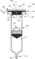
- FIG. 1 is a partial cross-sectional view of a syringe with syringe closure according to an embodiment.
- FIG. 2 is a partial, enlarged, exploded view of the syringe with syringe closure of FIG. 1 .
- FIG. 3 is a partial, enlarged, cross-sectional view of the syringe with syringe closure of FIG. 1 .
- FIG. 4 is a partial cross-sectional view of the syringe with syringe closure of FIG. 1 in combination with a plunger handle.
- FIG. 5 is a schematic view of the syringe with syringe closure of FIG. 1 in combination with a pneumatic driving system, or driver.
- FIG. 6 A is a partial cross-section view of another embodiment of a syringe for use with a syringe closure according to the embodiments disclosed herein.
- FIG. 6 B is a perspective view of a collar used in the syringe of FIG. 6 A to form or define a barrel flange.
- FIG. 7 A is a partial, enlarged, cross-sectional view of a syringe with syringe closure according to another embodiment.
- FIG. 7 B is a plan view of a collar used in the embodiment of FIG. 7 A .
- FIG. 8 B is a partial, enlarged, cross-sectional view of the embodiment of FIG. 8 A , with the fastener engaged with the barrel flange.
- the vented closure 106 is attached to the barrel 102 at the first end 112 (via a snap-fit, for example), and includes a stopper 120 , a cap 122 and a filter 124 .
- the stopper 120 is disposed over and/or in the opening 114 in communication with the bore 110 .
- the cap 122 includes a body 126 disposed over the stopper 120 , and a fastener 128 engaged with the barrel flange 116 .
- the filter 124 is disposed between the stopper 120 and the cap 122 , or in at least one of the stopper 120 and the cap 122 .
- the closure 106 may be removeable so that, after filling, a mechanical control mechanism can cooperate with the plunger 104 directly. That is, the closure 106 is designed to permit gas (e.g., air) to move the plunger 104 along the bore 110 .
- gas e.g., air
- a pneumatic system may be used during filling to move the plunger 104
- a large number of delivery systems use mechanical control mechanisms instead of gaseous ones.
- the closure 106 may be removed so that a first end 180 of a plunger handle 182 may be disposed through the opening 114 and into the bore 110 .
- the plunger 104 may have an attachment mechanism 184 formed therein or on a surface thereof that cooperates with the plunger handle 182 , for example the first end 180 .
- the first end 180 may have a thread formed thereon, and the plunger 104 may have a threaded bore formed therein, the first end 180 capable of being attached to the plunger 104 by screwing the first end 180 into the threaded bore 184 of the plunger 104 .
- the closure 106 is vented, which venting permits the syringe 100 to be used with a pneumatic driver during filing, and perhaps also with a gaseous driver as part of a delivery system.
- the stopper 120 and the body 126 of the cap 122 each have at least one through-lumen 190 , 192 according to the illustrated embodiment. See FIGS. 1 and 3 .
- the through-lumens 190 , 192 of the stopper 120 and cap 122 are aligned along a common longitudinal axis 194 , which axis 194 happens to be central axis of the syringe 100 as well.
- the filter 124 is disposed between the body 126 of the cap 122 and the stopper 120 along the axis 194 , and thus between the through lumen 190 of the stopper 120 and the through-lumen 192 of the cap 122 .
- the filter 124 may be made of filter media that can filter particle as small as 0.22 microns.
- the filter 124 may be joined to either the stopper 120 or the cap 122 .
- the filter 124 may be irreversibly joined to either the stopper 120 or the cap 122 through the use of adhesives, or common plastic joining techniques. These techniques may include spin welding, hot plate welding, radio-frequency (RF) welding, and laser welding, for example, and may be selected based on the materials used for the stopper 120 or cap 122 and the filter 124 .
- RF radio-frequency
- the filter 124 may be embedded in the stopper 120 or the cap 122 . According to such an embodiment, the filter 124 may be in one of the through-lumens 190 , 192 , for example, but still at the junction between the through-lumens 190 , 192 . According to still other embodiments, the filter 124 may be disposed not between the through-lumens 190 , 192 , but at an inner end of the through-lumen 190 or an outer end of the through lumen 192 . Further alternative arrangements are also possible.
- the closure 106 may be used with a pneumatic driver, as mentioned above.
- the closure 106 may be connected to the pneumatic driver, such as the driver 200 illustrated in FIG. 5 .
- the pneumatic driver 200 may be in the form of a pneumatic pump, for example, and may be capable of coupling pressure, vacuum or vent to the syringe 100 .
- the pneumatic driver may include a combination of valves and pressurized reservoirs.
- FIGS. 7 A-B , 8 A-B, 9 A-B An embodiment of the syringe 100 with closure 106 has been illustrated in FIGS. 1 - 5 , other embodiments are possible, as illustrated in FIGS. 7 A-B , 8 A-B, 9 A-B.
- the same numbering scheme has been used for the features of the syringe 100 , with the caveat that the above discussion as to variants of the syringe 100 (e.g., with reference to FIG. 6 ) applies with equal force to these additional embodiments.
- a numbering scheme where structures of the closure of FIGS. 7 A-B , 8 A-B, 9 A-B similar to those of the closure 106 have been numbered in a similar, but not identical, fashion has been adopted for readability.
- FIGS. 7 A and 7 B illustrate a vented closure 206 that is attached to the barrel 102 of the syringe 100 at the first end 112 .
- the vented closure 206 includes a stopper 120 , a cap 222 , and a filter 224 .
- the stopper 120 is disposed over and in the opening 114 in communication with the bore 110 .
- the cap 222 includes a body 226 disposed over the stopper 120 , and a fastener 228 engaged with the barrel flange 116 .
- the filter 224 is illustrated as disposed between the stopper 120 and the cap 222 .
- the embodiment of the cap 222 of FIGS. 7 A and 7 B differs from that of the embodiment of the cap 122 of FIGS. 1 - 5 in that the fastener 228 does not directly engage the barrel flange 116 . Instead, the cap 222 engages an intermediate structure that is disposed between the cap 222 and the barrel flange 116 , with surfaces of the cap 222 and the intermediate structure abutting (i.e. in direct contact) and surfaces of the intermediate structure and the barrel flange 116 abutting.
- the cap 222 includes a skirt 260 having a plurality of spaced barbs 262 , each of the barbs 262 being supported separately about the periphery of the cap 222 .
- Each of the barbs 262 has a head 264 with an inner surface 266 , which has a function similar to the surface 166 of the barb 162 of the cap 122 .
- the closure 206 also includes the afore-mentioned intermediate structure, or collar, 268 , which cooperates with the cap 222 , and in particular the barbs 262 , to secure the cap 222 to the barrel 102 of the syringe 100 .
- the collar 268 has a passage 270 , through which the barrel 102 of the syringe 100 is received when the collar 268 is disposed on the barrel 102 . Similar to the collar 142 , the barrel 102 may be disposed in the passage 270 as the collar 268 is moved from the second end 118 to the first end 112 . The movement of the collar 268 may be halted at the first end 112 by the barrel flange 116 , when a surface of the collar 268 abuts the barrel flange 116 . According to the illustrated embodiment, the collar 268 may have a recess 272 formed in an upper surface thereof to receive the barrel flange when an upper surface of the collar 268 abuts the barrel flange 116 .
- the collar 268 also has a rim 274 disposed radially outward from the passage 270 , and from the recess 272 .
- the rim 274 has a plurality of apertures 276 disposed about the periphery of the rim 274 . As illustrated, there are six apertures 276 , although according to other embodiments there may be a greater number or a lesser number of apertures 276 .
- the apertures 276 are spaced from each other in a pattern that is a mirror image about at least one axis, although again that need not be the case according to all embodiments.
- the apertures 276 are formed through the collar 268 , such that the barbs 262 are received through the apertures 276 , and abut an outer surface 278 of the collar 268 to secure the cap 222 to the barrel flange 116 .
- the surface of the recess 272 abuts the barrel flange 116 , while the opposing surfaces 266 , 278 of the barb 262 and the collar 268 also abut. In this fashion, the closure 206 is secured indirectly to the barrel flange 116 .
- the collar 268 may be positioned on the barrel 102 first, with the collar 268 being advanced from the second end 118 to the first end 112 , until the barrel flange 116 abuts the collar 268 and is received within the recess 272 .
- the filter 224 may be disposed between the stopper 120 and the cap 222 , and the cap 222 pressed downward towards the collar 268 .
- the barbs 262 may deflect outwardly as the barbs 262 are moved through the apertures 276 , until the head 264 of the barb 262 passes beyond the outer surface 278 of the collar 268 .
- the barbs 262 move inwardly and the surfaces 266 , 278 abut to hold the cap 222 to the collar 268 , with the barrel flange 116 , stopper 120 and filter 224 sandwiched between the cap 222 and the collar 268 .
- FIGS. 8 A and 8 B illustrated a vented closure 306 that is attached to the barrel 102 of the syringe 100 as the first end 112 .
- the vented closure 306 includes a stopper 120 , a cap 322 , and a filter 324 .
- the stopper 120 is disposed over and in the opening 114 in communication with the bore 110 .
- the cap 322 includes a body 326 disposed over the stopper 120 , and a fastener 328 engaged with the barrel flange 116 .
- the filter 324 is illustrated as disposed between the stopper 120 and the cap 322 .
- the fastener 328 (and in particular the barbs 362 ) are connected to the body 326 of the cap 322 by a hinge 370 .
- the hinge 370 is a living hinge, made of the material that forms the body 326 of the cap 322 and the skirt 360 .
- the hinge 370 may be a separate structure as to at least one of the body 326 and the skirt 360 , and joined to the body 326 and/or the skirt 360 .
- the hinge 370 permits the fastener 328 to be spaced at a distance from the syringe 100 during the attachment of the closure 306 to the syringe 100 .
- the filter 324 is disposed on the stopper 120 , or according to certain embodiments the filter 324 is joined to the stopper 120 ,
- the cap 322 is then disposed over the stopper 120 and filter 324 , as seen in FIG. 8 A .
- the fasteners 328 may then be brought from a first position or state illustrated in FIG. 8 A to a second position or state illustrated in FIG. 8 B .
- the barbs 362 are spaced radially outward of the body 326 of the cap 322 , thereby limiting interference between the barbs 362 and the barrel flange 116 (or collar, in those embodiments where included) as the cap 322 is fitted onto the syringe.
- the barbs 362 are brought into the second position where the surfaces 366 , 368 abut to secure the cap 322 (and the closure 306 ) to the syringe 100 .
- the fastener 428 is in the form of a C-shaped clamp 460 , as viewed in the cross-section of FIG. 9 A . It may be suggested that the clamp 460 performs the function of the skirt and the barb in the previous embodiments.
- the clamp 460 includes an upper section 462 , a lower section 464 , and a bridging section 466 that connects the upper section 462 to the lower section 464 .
- an inner surface 468 of the upper section 462 abuts an outer surface 470 of the body 426 of the cap 422 .
- an inner surface 472 of the lower section 464 abuts an outer surface 474 of the barrel flange 116 .
- the body 426 of the cap 422 , the filter 424 , the stopper flange 156 and the barrel flange 116 are sandwiched between the opposed inner surfaces 468 , 472 of the clamp 460 to secure the closure 406 to the syringe 100 , and each of the components in place.
- the clamp 460 has two mating halves 476 , 478 (which may be referred to as a left half 476 and a right half 478 according to the orientation of the clamp 460 in FIG. 9 B ) which connect to each other to hold the clamp 460 in place on the syringe 100 .
- one or more connectors may be disposed on the left half 476 or the right half 478 of the clamp 460 , or mating portions of the connectors may be disposed on the left half 476 or the right half 478 .
- the connectors hold the halves 476 , 478 of the clamp 460 together to ensure that the closure 406 remains secured to the syringe 100 .
- the upper section 462 has two connectors 480 , 482 disposed on opposite sides of the clamp 460 (which may also be opposite sides of the syringe 100 ).
- the lower section 464 may also have connectors (not shown) disposed on opposite sides of the clamp 460 . While one arrangement has been illustrated, this not the only possible configuration for the connectors.
- the connectors may be configured such that one half (e.g., the right half 478 ) has only the barbs 484 , and the other half (e.g., the left half 476 ) has only the recesses configured to receive the barbs 484 .
- the connectors of the upper section 462 may have barbs 484 on the right half 478 and recesses on the left half 476
- the lower section 464 has barbs on the left half 476 and recesses 486 on the right half 478 .
- the connector 480 may have a barb 484 on the right half 478 and a recess 486 on the left half 476
- the connector 482 has a barb 484 on the left half 476 and a recess 486 on the right half 478
- the connectors on the lower section 464 may be the same as their counterparts on the upper section 462 , or may be reversed.
- the halves 476 , 478 are advanced toward each other until the barbs 484 are advanced so far in the direction of the recess 486 that the barbs 484 and recess 486 mate, connecting the two halves 476 , 478 of the clamp 460 together.
- the body 426 , filter 424 and stopper 120 , and barrel flange 116 are disposed between the opposing surfaces 468 , 472 of the clamp 460 .
- FIGS. 9 A and 9 B it may also be possible to have a further embodiment, similar to that of FIGS. 9 A and 9 B , where the body 426 of the cap 422 is integrated into the upper section 462 of the clamp 460 .
- the body 426 may be integrated into the supper section 462 .
- the opening in the center of the upper section 462 may be smaller than is illustrated in FIGS. 9 A and 9 B , as it is not necessary to apply force on the separate element of the cap 422 when advancing the halves 476 , 478 toward each other.
- the syringe with syringe closure provides certain advantages relative to conventional syringes for use with pneumatic pumps.
- the closure permits use of a pneumatic driver during filling, which limits or eliminates a potential source of contaminants as the air may be filtered easily.
- the closure permits the syringe to be stored over a wide range of temperatures, while reducing the design burden on the plunger (particularly the plunger stopper) to provide the seal required during cryostorage.
- a syringe with incorporating such a closure can provide a ready-to-use delivery vessel, and one that is amenable to direct integration into instrumentation.
- the rigid nature of the container also may permit robotic instrumentation to facilitate connection for highly-scaled operations.
- Aspect 2 The syringe according to aspect 1, wherein the barrel flange comprises a collar disposed on the barrel at the end thereof.
- Aspect 3 The syringe according to aspect 1 or 2, wherein the stopper comprises an elastomeric stopper with a plug disposed within the bore and a stopper flange depending from an end of the stopper outside the bore.
- Aspect 5 The syringe according to any one of aspects 1-4, wherein the fastener comprises a downwardly depending skirt having a barb that engages the barrel flange.
- Aspect 7 The syringe according to aspect 5, wherein the closure comprises a collar that abuts the barrel flange, and the barb abuts a surface of the collar to engage the barrel flange.
- Aspect 8 The syringe according to any one of aspects 5-7, wherein the fastener is attached to the body of the cap by a hinge.
- Aspect 10 The syringe according to aspect 9, wherein the clamp is disposed about the periphery of the syringe, and is divided into at least two parts that are connected with the at least part of the stopper and the barrel flange disposed between opposing inner surfaces of the clamp.
- Aspect 11 The syringe according to aspect 9 or 10, wherein the body of the cap is separate from the clamp, and the body of the cap, the at least part of the stopper, and the barrel flange are disposed between the opposing inner surface of the clamp.
- Aspect 12 The syringe according to any one of aspects 1-11, wherein the cap is configured to compress the stopper to create a hermetic seal in the bore.
- Aspect 13 The syringe according to any one of the aspects 1-12, wherein the stopper and the body of the cap each have a through-lumen, the filter disposed between the through-lumen of the stopper and the through-lumen of the cap.
- Aspect 14 The syringe according to aspect 13, wherein the through-lumen of the stopper and the through-lumen of the cap are aligned along a common longitudinal axis.
- Aspect 15 The syringe according to any one of aspects 1-14, wherein the closure is removably attached to the barrel.
- Aspect 16 The syringe according to aspect 15, further comprising a plunger handle, the plunger handle disposed through the opening and into the bore, the plunger handle attachable to the plunger to control movement of the plunger along the bore.
- Aspect 17 The syringe according to any one of aspects 1-16, wherein the filter comprises 0.22 micron filter media.
- Aspect 18 The syringe according to any one of aspects 1-17, wherein the barrel comprises cyclic olefin copolymer.
- Aspect 19 The syringe according to any one of aspects 1-18, wherein the barrel has a second end opposite the end, the plunger moveable along the bore between the end and the second end, the second end comprising a tip in fluid communication with the bore.
- a processing set comprising tubing and at least one syringe according to aspect 19, with the tip of the at least one syringe connected to the tubing.
- a processing system comprising a pneumatic driver connected to the closure of a syringe according to any one of aspects 1-19.
Landscapes
- Health & Medical Sciences (AREA)
- Vascular Medicine (AREA)
- Engineering & Computer Science (AREA)
- Anesthesiology (AREA)
- Biomedical Technology (AREA)
- Heart & Thoracic Surgery (AREA)
- Hematology (AREA)
- Life Sciences & Earth Sciences (AREA)
- Animal Behavior & Ethology (AREA)
- General Health & Medical Sciences (AREA)
- Public Health (AREA)
- Veterinary Medicine (AREA)
- Infusion, Injection, And Reservoir Apparatuses (AREA)
Priority Applications (1)
| Application Number | Priority Date | Filing Date | Title |
|---|---|---|---|
| US17/466,083 US12303671B2 (en) | 2020-09-10 | 2021-09-03 | Syringe with syringe closure |
Applications Claiming Priority (2)
| Application Number | Priority Date | Filing Date | Title |
|---|---|---|---|
| US202063076843P | 2020-09-10 | 2020-09-10 | |
| US17/466,083 US12303671B2 (en) | 2020-09-10 | 2021-09-03 | Syringe with syringe closure |
Publications (2)
| Publication Number | Publication Date |
|---|---|
| US20220072234A1 US20220072234A1 (en) | 2022-03-10 |
| US12303671B2 true US12303671B2 (en) | 2025-05-20 |
Family
ID=77411637
Family Applications (1)
| Application Number | Title | Priority Date | Filing Date |
|---|---|---|---|
| US17/466,083 Active 2042-07-11 US12303671B2 (en) | 2020-09-10 | 2021-09-03 | Syringe with syringe closure |
Country Status (4)
| Country | Link |
|---|---|
| US (1) | US12303671B2 (de) |
| EP (1) | EP3967341B1 (de) |
| JP (1) | JP2022046439A (de) |
| CN (1) | CN114159647A (de) |
Families Citing this family (5)
| Publication number | Priority date | Publication date | Assignee | Title |
|---|---|---|---|---|
| JP7094906B2 (ja) * | 2019-02-15 | 2022-07-04 | 三菱重工業株式会社 | 流動性材料吐出装置 |
| USD920519S1 (en) * | 2019-06-28 | 2021-05-25 | Oertli-Instrumente Ag | Medical instrument for eye surgical purposes |
| CN120417953A (zh) * | 2022-12-01 | 2025-08-01 | 迪斯吉尼科斯有限公司 | 带帽注射器及其密封方法 |
| WO2024168243A1 (en) * | 2023-02-09 | 2024-08-15 | West Pharmaceutical Services, Inc. | Container systems and methods for cryogenic storge and delivery of bioink |
| CN118753559A (zh) * | 2024-09-06 | 2024-10-11 | 穆恩制药设备(杭州)有限公司 | 预充式注射器的无菌灌装方法 |
Citations (20)
| Publication number | Priority date | Publication date | Assignee | Title |
|---|---|---|---|---|
| US2186987A (en) * | 1938-08-05 | 1940-01-16 | Baxter Laboratories Inc | Filter flow device |
| US2372227A (en) * | 1940-12-24 | 1945-03-27 | Hugh W Sanford | Closure |
| US4231494A (en) * | 1979-03-22 | 1980-11-04 | Greenwood David L | Syringe adaptor assembly |
| US4251003A (en) * | 1979-01-19 | 1981-02-17 | Toni Casutt | Bottle closing device |
| US5019037A (en) * | 1989-07-06 | 1991-05-28 | Alcon Laboratories, Inc. | Pneumatic retinopexy injector |
| US5165560A (en) * | 1992-03-26 | 1992-11-24 | Genesis Industries, Inc. | Nonrotating hermetically sealed closure for bottle containing liquid |
| US5873499A (en) * | 1996-08-14 | 1999-02-23 | Scientific Resources, Inc. | Pressure breakaway dispensing gun |
| US5887764A (en) * | 1996-11-27 | 1999-03-30 | Ennis, Iii; James F. | Apparatus for a pressurized injector |
| US6296625B1 (en) * | 1999-06-26 | 2001-10-02 | Arzneimittel Gmbh Apotheker Vetter & Co. Ravensburg | Finger brace for hypodermic syringe |
| US6663601B2 (en) | 2001-04-16 | 2003-12-16 | Becton Dickinson And Company | Sterilizable transfer or storage device for medicaments, drugs and vaccines |
| US7810529B2 (en) * | 2000-02-11 | 2010-10-12 | Medical Instill Technologies, Inc. | Device with needle penetrable and laser resealable portion |
| US20120232524A1 (en) * | 2011-03-07 | 2012-09-13 | Hyun Dongchul D | Multi-purpose syringe |
| US20140276415A1 (en) * | 2013-03-15 | 2014-09-18 | Carefusion 303, Inc. | Infusion system with dual-chambered reservoir |
| US20140263403A1 (en) * | 2013-03-15 | 2014-09-18 | Nordson Corporation | Liquid Dispensing Syringe |
| US20160081849A1 (en) * | 2014-09-18 | 2016-03-24 | Ethicon Endo-Surgery, Inc. | Therapeutic agent delivery device |
| US20160243309A1 (en) * | 2015-02-20 | 2016-08-25 | Regeneron Pharmaceuticals, Inc. | Syringe systems, piston seal systems, stopper systems, and methods of use and assembly |
| WO2018065880A1 (en) * | 2016-10-05 | 2018-04-12 | Cane' S.P.A. | Device for filling and priming syringes |
| EP3329947A2 (de) * | 2016-12-01 | 2018-06-06 | Fenwal, Inc. | Füll- und endbearbeitungssysteme und -verfahren |
| US20200039698A1 (en) * | 2017-03-27 | 2020-02-06 | Musashi Engineering, Inc. | Lid for liquid material storage container, and liquid material storage container |
| EP3669910A1 (de) * | 2018-12-19 | 2020-06-24 | Fenwal, Inc. | Einwegspritze zur verwendung mit pneumatischen treibern |
Family Cites Families (1)
| Publication number | Priority date | Publication date | Assignee | Title |
|---|---|---|---|---|
| JP4050579B2 (ja) * | 2002-09-11 | 2008-02-20 | テルモ株式会社 | プレフィルドシリンジ |
-
2021
- 2021-08-19 EP EP21192150.7A patent/EP3967341B1/de active Active
- 2021-09-02 JP JP2021143187A patent/JP2022046439A/ja active Pending
- 2021-09-03 CN CN202111032861.4A patent/CN114159647A/zh active Pending
- 2021-09-03 US US17/466,083 patent/US12303671B2/en active Active
Patent Citations (22)
| Publication number | Priority date | Publication date | Assignee | Title |
|---|---|---|---|---|
| US2186987A (en) * | 1938-08-05 | 1940-01-16 | Baxter Laboratories Inc | Filter flow device |
| US2372227A (en) * | 1940-12-24 | 1945-03-27 | Hugh W Sanford | Closure |
| US4251003A (en) * | 1979-01-19 | 1981-02-17 | Toni Casutt | Bottle closing device |
| US4231494A (en) * | 1979-03-22 | 1980-11-04 | Greenwood David L | Syringe adaptor assembly |
| US5019037A (en) * | 1989-07-06 | 1991-05-28 | Alcon Laboratories, Inc. | Pneumatic retinopexy injector |
| US5165560A (en) * | 1992-03-26 | 1992-11-24 | Genesis Industries, Inc. | Nonrotating hermetically sealed closure for bottle containing liquid |
| US5873499A (en) * | 1996-08-14 | 1999-02-23 | Scientific Resources, Inc. | Pressure breakaway dispensing gun |
| US5887764A (en) * | 1996-11-27 | 1999-03-30 | Ennis, Iii; James F. | Apparatus for a pressurized injector |
| US6296625B1 (en) * | 1999-06-26 | 2001-10-02 | Arzneimittel Gmbh Apotheker Vetter & Co. Ravensburg | Finger brace for hypodermic syringe |
| US7810529B2 (en) * | 2000-02-11 | 2010-10-12 | Medical Instill Technologies, Inc. | Device with needle penetrable and laser resealable portion |
| US6663601B2 (en) | 2001-04-16 | 2003-12-16 | Becton Dickinson And Company | Sterilizable transfer or storage device for medicaments, drugs and vaccines |
| US20120232524A1 (en) * | 2011-03-07 | 2012-09-13 | Hyun Dongchul D | Multi-purpose syringe |
| US20160175529A1 (en) | 2011-03-07 | 2016-06-23 | Medela Holding Ag | Multi-purpose syringe |
| US20140276415A1 (en) * | 2013-03-15 | 2014-09-18 | Carefusion 303, Inc. | Infusion system with dual-chambered reservoir |
| US20140263403A1 (en) * | 2013-03-15 | 2014-09-18 | Nordson Corporation | Liquid Dispensing Syringe |
| US20160081849A1 (en) * | 2014-09-18 | 2016-03-24 | Ethicon Endo-Surgery, Inc. | Therapeutic agent delivery device |
| US20160243309A1 (en) * | 2015-02-20 | 2016-08-25 | Regeneron Pharmaceuticals, Inc. | Syringe systems, piston seal systems, stopper systems, and methods of use and assembly |
| WO2018065880A1 (en) * | 2016-10-05 | 2018-04-12 | Cane' S.P.A. | Device for filling and priming syringes |
| EP3329947A2 (de) * | 2016-12-01 | 2018-06-06 | Fenwal, Inc. | Füll- und endbearbeitungssysteme und -verfahren |
| US20200039698A1 (en) * | 2017-03-27 | 2020-02-06 | Musashi Engineering, Inc. | Lid for liquid material storage container, and liquid material storage container |
| EP3669910A1 (de) * | 2018-12-19 | 2020-06-24 | Fenwal, Inc. | Einwegspritze zur verwendung mit pneumatischen treibern |
| US20200197942A1 (en) | 2018-12-19 | 2020-06-25 | Fenwal, Inc. | Methods and systems for mating disposable syringes with pneumatic drivers without breaking sterility |
Non-Patent Citations (1)
| Title |
|---|
| Extended European Search Report for EP 21192150.7 dated Jan. 4, 2022; 9 pages. |
Also Published As
| Publication number | Publication date |
|---|---|
| EP3967341B1 (de) | 2025-07-09 |
| EP3967341A1 (de) | 2022-03-16 |
| EP3967341C0 (de) | 2025-07-09 |
| CN114159647A (zh) | 2022-03-11 |
| US20220072234A1 (en) | 2022-03-10 |
| JP2022046439A (ja) | 2022-03-23 |
Similar Documents
| Publication | Publication Date | Title |
|---|---|---|
| US12303671B2 (en) | Syringe with syringe closure | |
| US20240108548A1 (en) | Pre-filled diluent syringe vial adapter | |
| US5445630A (en) | Spike with luer fitting | |
| US5391150A (en) | IV bag with needleless connector ports | |
| US5405333A (en) | Liquid medicament bag with needleless connector fitting using boat assembly | |
| US10470974B2 (en) | System for closed transfer of fluids with a locking member | |
| EP2271387B1 (de) | Flüssigkeitsübertragungsvorrichtung mit doppelcontainer | |
| US7905873B2 (en) | Port assembly for use with needleless connector | |
| KR101514915B1 (ko) | 수부재 | |
| AU2011217306B2 (en) | Closure cap for a receptacle for receiving medical liquids, and receptacle | |
| EP3562753B1 (de) | Mit einer verbindungsvorrichtung betätigter behälterverschluss | |
| JP2018507755A (ja) | シリンジコネクタに使用する隔膜ホルダー | |
| KR20220018086A (ko) | 단일 또는 다중 용기를 위한 병합 장치 | |
| EP3107600B1 (de) | Ansaugeventilgerät | |
| EP3562752B1 (de) | Durch drehung betätigter behälterverschluss | |
| US10426942B2 (en) | Connection structure for IV tube of IV infusion set | |
| AU2016276548A1 (en) | Improved components of a fluid transfer apparatus |
Legal Events
| Date | Code | Title | Description |
|---|---|---|---|
| FEPP | Fee payment procedure |
Free format text: ENTITY STATUS SET TO UNDISCOUNTED (ORIGINAL EVENT CODE: BIG.); ENTITY STATUS OF PATENT OWNER: LARGE ENTITY |
|
| STPP | Information on status: patent application and granting procedure in general |
Free format text: DOCKETED NEW CASE - READY FOR EXAMINATION |
|
| AS | Assignment |
Owner name: FENWAL, INC., ILLINOIS Free format text: ASSIGNMENT OF ASSIGNORS INTEREST;ASSIGNOR:WEGENER, CHRISTOPHER J.;REEL/FRAME:057837/0281 Effective date: 20210913 |
|
| STPP | Information on status: patent application and granting procedure in general |
Free format text: NON FINAL ACTION MAILED |
|
| STPP | Information on status: patent application and granting procedure in general |
Free format text: RESPONSE TO NON-FINAL OFFICE ACTION ENTERED AND FORWARDED TO EXAMINER |
|
| STPP | Information on status: patent application and granting procedure in general |
Free format text: FINAL REJECTION MAILED |
|
| STPP | Information on status: patent application and granting procedure in general |
Free format text: DOCKETED NEW CASE - READY FOR EXAMINATION |
|
| STPP | Information on status: patent application and granting procedure in general |
Free format text: NON FINAL ACTION MAILED |
|
| STPP | Information on status: patent application and granting procedure in general |
Free format text: RESPONSE TO NON-FINAL OFFICE ACTION ENTERED AND FORWARDED TO EXAMINER |
|
| STPP | Information on status: patent application and granting procedure in general |
Free format text: NOTICE OF ALLOWANCE MAILED -- APPLICATION RECEIVED IN OFFICE OF PUBLICATIONS |
|
| STCF | Information on status: patent grant |
Free format text: PATENTED CASE |