US12291663B2 - Matrix formulation for polymer dispersed liquid crystal displays in low power direct current (DC) electromagnetic field application - Google Patents
Matrix formulation for polymer dispersed liquid crystal displays in low power direct current (DC) electromagnetic field application Download PDFInfo
- Publication number
- US12291663B2 US12291663B2 US16/692,567 US201916692567A US12291663B2 US 12291663 B2 US12291663 B2 US 12291663B2 US 201916692567 A US201916692567 A US 201916692567A US 12291663 B2 US12291663 B2 US 12291663B2
- Authority
- US
- United States
- Prior art keywords
- formulation
- electromagnetic field
- polymer matrix
- product
- pdlc
- Prior art date
- Legal status (The legal status is an assumption and is not a legal conclusion. Google has not performed a legal analysis and makes no representation as to the accuracy of the status listed.)
- Active, expires
Links
Images


Classifications
-
- C—CHEMISTRY; METALLURGY
- C09—DYES; PAINTS; POLISHES; NATURAL RESINS; ADHESIVES; COMPOSITIONS NOT OTHERWISE PROVIDED FOR; APPLICATIONS OF MATERIALS NOT OTHERWISE PROVIDED FOR
- C09K—MATERIALS FOR MISCELLANEOUS APPLICATIONS, NOT PROVIDED FOR ELSEWHERE
- C09K19/00—Liquid crystal materials
- C09K19/52—Liquid crystal materials characterised by components which are not liquid crystals, e.g. additives with special physical aspect: solvents, solid particles
- C09K19/54—Additives having no specific mesophase characterised by their chemical composition
- C09K19/542—Macromolecular compounds
- C09K19/544—Macromolecular compounds as dispersing or encapsulating medium around the liquid crystal
-
- C—CHEMISTRY; METALLURGY
- C08—ORGANIC MACROMOLECULAR COMPOUNDS; THEIR PREPARATION OR CHEMICAL WORKING-UP; COMPOSITIONS BASED THEREON
- C08F—MACROMOLECULAR COMPOUNDS OBTAINED BY REACTIONS ONLY INVOLVING CARBON-TO-CARBON UNSATURATED BONDS
- C08F220/00—Copolymers of compounds having one or more unsaturated aliphatic radicals, each having only one carbon-to-carbon double bond, and only one being terminated by only one carboxyl radical or a salt, anhydride ester, amide, imide or nitrile thereof
- C08F220/02—Monocarboxylic acids having less than ten carbon atoms; Derivatives thereof
- C08F220/10—Esters
- C08F220/12—Esters of monohydric alcohols or phenols
- C08F220/14—Methyl esters, e.g. methyl (meth)acrylate
-
- G—PHYSICS
- G02—OPTICS
- G02F—OPTICAL DEVICES OR ARRANGEMENTS FOR THE CONTROL OF LIGHT BY MODIFICATION OF THE OPTICAL PROPERTIES OF THE MEDIA OF THE ELEMENTS INVOLVED THEREIN; NON-LINEAR OPTICS; FREQUENCY-CHANGING OF LIGHT; OPTICAL LOGIC ELEMENTS; OPTICAL ANALOGUE/DIGITAL CONVERTERS
- G02F1/00—Devices or arrangements for the control of the intensity, colour, phase, polarisation or direction of light arriving from an independent light source, e.g. switching, gating or modulating; Non-linear optics
- G02F1/01—Devices or arrangements for the control of the intensity, colour, phase, polarisation or direction of light arriving from an independent light source, e.g. switching, gating or modulating; Non-linear optics for the control of the intensity, phase, polarisation or colour
- G02F1/13—Devices or arrangements for the control of the intensity, colour, phase, polarisation or direction of light arriving from an independent light source, e.g. switching, gating or modulating; Non-linear optics for the control of the intensity, phase, polarisation or colour based on liquid crystals, e.g. single liquid crystal display cells
- G02F1/133—Constructional arrangements; Operation of liquid crystal cells; Circuit arrangements
- G02F1/13306—Circuit arrangements or driving methods for the control of single liquid crystal cells
-
- G—PHYSICS
- G02—OPTICS
- G02F—OPTICAL DEVICES OR ARRANGEMENTS FOR THE CONTROL OF LIGHT BY MODIFICATION OF THE OPTICAL PROPERTIES OF THE MEDIA OF THE ELEMENTS INVOLVED THEREIN; NON-LINEAR OPTICS; FREQUENCY-CHANGING OF LIGHT; OPTICAL LOGIC ELEMENTS; OPTICAL ANALOGUE/DIGITAL CONVERTERS
- G02F1/00—Devices or arrangements for the control of the intensity, colour, phase, polarisation or direction of light arriving from an independent light source, e.g. switching, gating or modulating; Non-linear optics
- G02F1/01—Devices or arrangements for the control of the intensity, colour, phase, polarisation or direction of light arriving from an independent light source, e.g. switching, gating or modulating; Non-linear optics for the control of the intensity, phase, polarisation or colour
- G02F1/13—Devices or arrangements for the control of the intensity, colour, phase, polarisation or direction of light arriving from an independent light source, e.g. switching, gating or modulating; Non-linear optics for the control of the intensity, phase, polarisation or colour based on liquid crystals, e.g. single liquid crystal display cells
- G02F1/133—Constructional arrangements; Operation of liquid crystal cells; Circuit arrangements
- G02F1/1333—Constructional arrangements; Manufacturing methods
- G02F1/1334—Constructional arrangements; Manufacturing methods based on polymer dispersed liquid crystals, e.g. microencapsulated liquid crystals
-
- C—CHEMISTRY; METALLURGY
- C09—DYES; PAINTS; POLISHES; NATURAL RESINS; ADHESIVES; COMPOSITIONS NOT OTHERWISE PROVIDED FOR; APPLICATIONS OF MATERIALS NOT OTHERWISE PROVIDED FOR
- C09K—MATERIALS FOR MISCELLANEOUS APPLICATIONS, NOT PROVIDED FOR ELSEWHERE
- C09K19/00—Liquid crystal materials
- C09K19/52—Liquid crystal materials characterised by components which are not liquid crystals, e.g. additives with special physical aspect: solvents, solid particles
- C09K19/54—Additives having no specific mesophase characterised by their chemical composition
- C09K19/542—Macromolecular compounds
- C09K2019/546—Macromolecular compounds creating a polymeric network
Definitions
- the present invention relates to additive manufacturing, and more particularly, this invention relates to a polymer matrix formulation for low power direct current (DC) electromagnetic field conditions, in particular to a photosensitive thermosetting matrix for high optical contrast with low power DC electromagnetic field conditions.
- DC direct current
- PDLC Current polymer dispersed liquid crystal
- AC alternating current
- DC direct current
- a pre-polymer matrix formulation for a polymer dispersed liquid crystal (PDLC) display includes a monofunctional monomer, a trifunctional oligomer, and a trifunctional monomer.
- a product includes a PDLC display formulation comprising a polymer matrix having a plurality of liquid crystal (LC) domains dispersed therein, wherein the polymer matrix comprises a polymerized product of a monofunctional monomer, a trifunctional oligomer, and a trifunctional monomer, and a pair of electrodes having the PDLC display formulation positioned therebetween.
- the PDLC display formulation is characterized as having a substantially constant optical transparency during application of a low power direct current (DC) electromagnetic field between the electrodes for a predefined duration of time.
- DC direct current
- a system includes a PDLC display formulation comprising a polymer matrix having a plurality of LC domains dispersed therein, a first substrate and a second substrate, where the PDLC display formulation is disposed between the first and second substrates.
- the polymer matrix includes a polymerized product of a monofunctional monomer, a trifunctional oligomer, and a trifunctional monomer.
- the system includes at least one electrode layer where the PDLC display formulation is positioned adjacent to the at least one electrode layer, and a power circuit for applying a DC electromagnetic field across the at least one electrode layer.
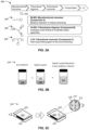
- FIG. 1 is a schematic diagram of LC domain orientation with no field applied and potential LC domain orientation conformations during static field application.
- FIG. 2 A is an optimized formulation of a pre-polymer matrix for mitigating transparency relaxation, according to one aspect of an inventive concept.
- FIG. 2 B is a is a schematic diagram of the PDLC mixing procedure, according to one aspect of an inventive concept.
- FIG. 2 C is a schematic diagram of photo-induced phase separation of a PDLC display formulation, according to one aspect of an inventive concept.
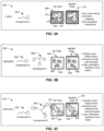
- FIG. 3 A is a schematic diagram of a pre-polymer formulation having nearly 100 wt % of monofunctional monomer (component A), according to one aspect of an inventive concept.
- FIG. 3 B is a schematic diagram of a pre-polymer formulation having about 80 wt % of monofunctional monomer (component A) and about 20 wt % of trifunctional monomer (component C), according to one aspect of an inventive concept.
- FIG. 3 C is a schematic diagram of a pre-polymer formulation having about 80 wt % monofunctional monomer (component A) and about 20 wt % trifunctional oligomer (component B), according to one aspect of an inventive concept.
- FIG. 4 is a schematic diagram of an optimized pre-polymer formulation for polymer dispersed liquid crystal (PDLC) display formulation with DC electromagnetic field application, according to one aspect of an inventive concept.
- PDLC polymer dispersed liquid crystal
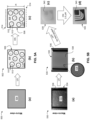
- Parts (a), (b), and (c) of FIG. 5 A are schematic diagrams of a micro-view of forming a PDLC display formulation, according to one aspect of an inventive concept.
- Parts (a), (b), (c), and (d) of FIG. 5 B are images of a macro-view of forming a PDLC display formulation, according to one aspect of an inventive concept.
- FIG. 6 is a schematic drawing of a PDLC display stacking structure, according to one aspect of an inventive concept.
- FIG. 7 A is a schematic diagram of components of a pre-polymer formulation, according to one aspect of an inventive concept.
- FIG. 7 B is a plot of transmission data as a function of applied DC electromagnetic field of various formulations of pre-polymer matrix during DC electromagnetic field application, according to one aspect of an inventive concept.
- FIG. 7 C is a scanning electron microscope (SEM) image of LC domains in a polymer matrix having 90 wt % Component A, according to one aspect of an inventive concept.
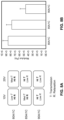
- FIG. 8 A is a transmissivity vs relaxation summary diagram of various formulations of pre-polymer matrix, according to various aspect of an inventive concepts.
- FIG. 8 B is a plot of the modulus of pre-polymer formulations having increased ratios of component A to component C, according to various aspect of an inventive concepts.
- FIG. 9 is a plot of relaxation data comparing formulations having different concentrations of component C, according to one aspect of an inventive concept.
- FIG. 10 is a plot of relaxation data generated from a commercially available matrix resin compared to an inventive matrix formulation, according to one aspect of an inventive concept.
- FIG. 11 is a plot of transmission of an optimized PDLC display formulation over an extended period of time of applied direct current, according to one aspect of an inventive concept.
- a pre-polymer matrix formulation for a polymer dispersed liquid crystal (PDLC) display includes a monofunctional monomer, a trifunctional oligomer, and a trifunctional monomer.
- a product in another general aspect of an inventive concept, includes a PDLC display formulation comprising a polymer matrix having a plurality of liquid crystal (LC) domains dispersed therein, wherein the polymer matrix comprises a polymerized product of a monofunctional monomer, a trifunctional oligomer, and a trifunctional monomer, and a pair of electrodes having the PDLC display formulation positioned therebetween.
- the PDLC display formulation is characterized as having a substantially constant optical transparency during application of a low power direct current (DC) electromagnetic field between the electrodes for a predefined duration of time.
- DC direct current
- a system in yet another general aspect of an inventive concept, includes a PDLC display formulation comprising a polymer matrix having a plurality of LC domains dispersed therein, a first substrate and a second substrate, where the PDLC display formulation is disposed between the first and second substrates.
- the polymer matrix includes a polymerized product of a monofunctional monomer, a trifunctional oligomer, and a trifunctional monomer.
- the system includes at least one electrode layer where the PDLC display formulation is positioned adjacent to the at least one electrode layer, and a power circuit for applying a DC electromagnetic field across the at least one electrode layer.
- Processing PDLC displays includes preparing a pre-polymer and liquid crystal (LC) mixture, followed by polymerization by ultra-violet (UV) light to induce phase separation of the LC domains to scatter light.
- LC liquid crystal
- UV ultra-violet
- the transition of the PDLC from opaque (off) to transparent (on) has typically been powered in conventional systems using an alternating current (AC) electromagnetic field.
- the AC electromagnetic field has long been considered to be preferred to maintain high optical transparency over extended periods of time.
- an optimized formulation of flexible polymer dispersed liquid crystal (PDLC) displays may be used in low power direct current (DC) electromagnetic field applications.
- DC direct current
- a transparency effect is generated.
- Applying a DC electromagnetic field to conventional PDLC displays optimized for AC electromagnetic field causes the displays to exhibit transparency for the first ⁇ 10 ms, but then initial transparency is followed by a quick decay in transparency to a more translucent state.
- a finely-tuned acrylate-based formulation as the PDLC thermosetting matrix may achieve non-variable optical clarity with DC electromagnetic field at low-power conditions.
- the matrix remains intact, e.g., without breakdown of the matrix.
- the transparency relaxation effect typically demonstrated with commercial formulations of a polymer matrix of a PDLC display under application of a DC electromagnetic field may be explained by the anchoring effect of the LC molecules of an LC domain by the surrounding matrix.
- Anchoring may be defined as interfacial forces from the polymer matrix acting upon the LC molecules (that form an LC domain).
- the modulus of the matrix is low, then there is low probability of anchoring the LC domains dispersed through the matrix, and thus there tends to be minimal relaxation of the aligned orientation of the LC molecules.
- the modulus of the matrix is high, then there is a high probability of anchoring of the LC molecules, and the surrounding matrix interacts with the LC domains thereby causing relaxation of the aligned orientation of the LC molecules, and consequently loss of transparency.
- FIG. 1 illustrates the restrictions on LC domains 100 comprised of LC molecules 102 that may cause the relaxation of transparency during initial high optical contrast during an applied field.
- FIG. 1 shows a schematic drawing of an LC domain 100 in a polymer matrix 104 of a PDLC display having no field applied where the LCs molecules 102 are in random order. Under applied field, when there are no relaxation effects, the LC molecules 102 are aligned in orientation of the field. However, a polymer matrix 106 may incur modular stress on the LC molecules 102 as shown with the LC domains 108 , 112 , and 116 under applied field.
- Exposure of the pre-polymer matrix formulation including LC molecules to UV irradiation causes domains of LC molecules as a result of photo-induced phase separation.
- the PDLC display formulation is formed after UV exposure and includes LC domains trapped in the polymer matrix.
- the orientation of the LC molecules within the LC domains of the PDLC display formulation may be affected by the components of the polymer matrix formulation.
- Anchoring of the LC molecules in the LC domains may result in, but are not limited to, spherical LC domains 108 , oblong LC domains 112 , and interconnected neighboring LC domains 116 .
- a spherical LC domain 108 may include an anchoring effect of the LC molecules 110 such that only the centermost LC molecules are aligned and the LC molecules on the edges of the LC domain 108 may be slightly soluble with the matrix resulting in a disorientation of the molecules 110 .
- An oblong LC domain 112 may be formed by high matrix moduli having a similar effect to spherical LCs in which only the centermost LC molecules 114 may be aligned.
- Interconnected neighboring LC domains 116 may have some anchoring effects in between the interconnect as well as on the sides of the LC domains 116 , and the matrix may affect more portions of the LC molecules 118 within the domains 116 .
- a matrix formulation for a PDLC display that operates under an applied DC electromagnetic field includes a finely tuned formulation to mitigate optical relaxation of the LC component of the matrix.
- an apparatus includes a PDLC display formulation for non-variable high optical contrast under low power DC electromagnetic field conditions.
- a photosensitive thermosetting pre-polymer matrix may aid polymerization-induced phase separation from the liquid crystal (LC) during curing of the PDLC display media (e.g., UV light exposure).
- the formulation described herein has been optimized to maintain a steady-state transparency during DC power application.
- Typical commercial polymer matrix formulations for AC electromagnetic fields are optimized for the initial 10 millisecond (ms) to 100 ms pulsed current of optical clarity. According to various approaches described here, a polymer matrix formulation designed for DC applied electromagnetic fields may sustain the optical clarity for the entire duration of applying the DC electromagnetic field.
- a pre-polymer formulation for a PDLC display may include three components, where each component has at least one reactive functional group.
- the three components of the pre-polymer formulation may vary in molecular weight and functionality.
- the pre-polymer formulation is an acrylate-based formulation where each of the components includes an acrylate.
- one of the three components may be included to fine tune the LC domain size in order to reduce transparency relaxation when a static field is applied across the PDLC display, while maintaining a high electro-optical contrast ratio.
- two components of the three components of the pre-polymer formulation may contribute to matrix stress reduction on the LC domains.
- the pre-polymer formulation is a photosensitive thermosetting matrix formulation.
- a mixture of the pre-polymer formulation and the liquid crystal (LC) molecules undergo phase separation where the LC molecules form LC domains with minimal anchoring caused by the polymer matrix.
- the pre-polymer formulation may be tailored to optimize a fast (e.g., less than 10 seconds) photopolymerization-induced phase separation of the LC molecules from the multicomponent polymer matrix.
- the photosensitive thermosetting matrix formulation is optimized to reduce anchoring with the polymer matrix and reduce solubility of the LC in the polymer matrix post phase separation.
- the liquid crystal compounds within a domain may be randomly oriented until aligned in the direction of an applied electromagnetic field.
- FIGS. 2 A- 2 C depict a pre-polymer formulation 200 for a polymer dispersed liquid crystal (PDLC) display, in accordance with one aspect of an inventive concept.
- the present pre-polymer formulation 200 may be implemented in conjunction with features from any other aspect of an inventive concept listed herein, such as those described with reference to the other FIGS.
- PDLC polymer dispersed liquid crystal
- the pre-polymer formulation 200 and others presented herein may be used in various applications and/or in permutations which may or may not be specifically described in the illustrative aspects of an inventive concepts listed herein.
- the pre-polymer formulation 200 presented herein may be used in any desired environment.
- a pre-polymer matrix formulation 200 for a PDLC display includes compounds having at least one reactive functional group 202 .
- the functional group may be an acrylate.
- the functional group may be a mercaptan.
- the functional group may be an epoxide.
- the functional group may be a vinyl group.
- the components of the pre-polymer matrix may include a combination of reactive functional groups.
- the following combinations of reactive functional groups may include: acrylate-acrylate, acrylate-mercaptan, mercaptan-vinyl, mercaptan-epoxide, epoxide-epoxide, etc.
- the pre-polymer matrix formulation 200 includes a monofunctional monomer 204 (e.g., component A), a trifunctional oligomer 206 (e.g., component B), and a trifunctional monomer 208 (e.g., component C).
- the monofunctional monomer 204 may provide a modulus reduction to reduce anchoring of the liquid crystal (LC) domains.
- the trifunctional oligomer 206 may increase cross-linking to moderate phase separation during photopolymerization curing of the pre-polymer.
- the trifunctional monomer 208 may function as a fast cross-linker to fine tune anchoring of the LC domains in the polymer matrix of the PDLC display. In other words, the trifunctional monomer 208 may induce cross-linking of the pre-polymer matrix formulation 200 in a short duration of time (e.g., less than 10 seconds).
- the duration of time to cure a PDLC formulation display may depend on the thickness of the display.
- the speed of the cure may be very quick (e.g., the duration of time of curing is less than 10 seconds).
- the formulation may be cured in at least 2 seconds and no more than 5 seconds.
- an optimized formulation for the pre-polymer matrix formulation may include each component in the following concentration ranges.
- the concentration of the monofunctional monomer 204 may be in a range of about 80 wt % to about 90 wt % of the total weight of the pre-polymer matrix formulation 200 .
- the concentration of the trifunctional oligomer 206 may be in a range of about 10 wt % to about 20 wt % of the total weight of the pre-polymer matrix formulation 200 .
- the concentration of the trifunctional monomer 208 may be in a range of about 1 wt % to about 2 wt % of the total weight of the pre-polymer matrix formulation 200 .
- the pre-polymer formulation is added to a mixture of liquid crystals and cured to form a PDLC display formulation.
- a PDLC display formulation includes a plurality of LC domains dispersed in a polymer matrix formed from the pre-polymer formulation described herein.
- a process 220 of forming PDLC display formulation 224 may include combining the pre-polymer matrix formulation 200 with a liquid crystal (LC) component 222 .
- the liquid crystal component 222 may be dissolved in the pre-polymer matrix formulation 200 to form a PDLC display formulation 224 .
- the PDLC display formulation 224 may be deposited between two transparent electrodes 225 .
- the PDLC display formulation 224 has a known thickness th between the electrodes 225 .
- the UV-irradiated PDLC display formulation 226 undergoes a phase separation thereby resulting in the formation of LC domains 210 .
- a plurality of LC domains 210 may be dispersed in the cured matrix formulation 228 , with each of the LC domains 210 including LC molecules 212 . LC domains do not form until photo-induced phase separation following exposure to UV light.
- the pre-polymer matrix formulation 200 may be configured to adjust a morphology of each LC domain 210 to have an average diameter d in a range of about 500 nanometers (nm) to about 2 microns ( ⁇ m) as a result of UV exposure and photo-induced phase separation.
- a characteristic length of the LC domains containing LC molecules may vary from ⁇ 500 nm to 2 ⁇ m.
- the size of the LC domain may be tuned by varying the ratios of components A, B and C of the pre-polymer matrix formulation 200 .
- the components of the pre-polymer matrix of the PDLC display optimized for applying a DC electromagnetic field and mitigating transparency relaxation are illustrated in the schematic drawings of the PDLC microstructures of FIGS. 3 A- 3 C .
- microstructures of the optimal formations were analyzed and the optical contrast observed under applied DC electromagnetic fields.
- LC domain morphology after phase separation within the polymer matrix may be directly dependent on the matrix curing kinetics.
- the LC molecules may exhibit decreased solubility in the matrix as the polymer matrix crosslinks with UV light exposure.
- the LC molecules may exhibit decreased solubility in the polymer matrix as the matrix cures from a liquid to a gel, solid, etc. Increasing solubility of LC molecules in the cured polymer matrix may increase anchoring of the LC molecules to the polymer matrix and cause the aforementioned relaxation defects in LC domain morphology.
- each component (monofunctional monomer 204 , trifunctional oligomer 206 , and/or trifunctional monomer 208 ) affect anchoring of the LC domains in the matrix of the PDLC display formulation.
- a pre-polymer formulation 300 that includes about 100 wt % of monofunctional monomer 204 forms a PDLC display formulation 306 having polymer matrix 308 formed from the monofunctional monomer 204 and a plurality of LC domains 310 containing LC molecules 312 .
- increasing the monofunctional monomer 204 component may reduce cross-linking, thereby resulting in larger LC domains 310 and less anchoring effects.
- Anchoring effects may be reduced due to a decreased concentration of LC domains 310 trapped in the polymer matrix 308 as the polymerization rate decreases with increasing monofunctional monomer 204 concentration.
- anchoring effects may be reduced with increasing monofunctional monomer 204 due to a reduction in the modulus (i.e. less stress on the LC domains 310 ).
- the decreased cross-linked network e.g., cross-linking may be negligible at a concentration of 100 wt % monofunctional monomer 204
- the LC domains 310 may coalesce (arrow 314 ).
- concentrations of monofunctional monomer 204 at greater than 98 wt % there tends to be less relaxation of the LC domains 310 .
- Reducing cross-linking may also lead to decreased stress on the LC domains 310 and decreased relaxation as the modulus decreases along with the elasticity of the polymer matrix 308 .
- reducing cross-linking to a minimum i.e. ⁇ 100% monofunctional monomer
- entirely spherical LC domains 310 may likely result and coalescence may likely occur.
- the PDLC display formulation 306 may not experience a steady transparency effect with the applied DC electromagnetic field 316 .
- the LC domains 310 may likely be too large to scatter light in the off state (No Field).
- a pre-polymer formulation 300 of nearly 100 wt % monofunctional monomer 204 may demonstrate no cross-linking, the LC domains 310 may coalesce within the polymer matrix 308 , and there may be no orientation restrictions.
- the LC molecules may align during an applied field without restriction.
- no scattering effects will be present during an applied field due to the larger LC domain size.
- the display may not transition from opaque to clear (e.g., transparent) during application of an electromagnetic field.
- FIGS. 3 B and 3 C illustrate a two component system of pre-polymer matrix formulation 320 and 330 , respectively.
- a non-variable optical transparency may be obtained in a two-component system with high concentrations (90-95%) of monofunctional monomer 204 and a second component.
- a lower contrast ratio may result in the two component system with high concentrations of monofunctional monomer and a second component.
- a higher cross-link density may reduce overall LC domain size, increasing the off-state light scattering property (i.e. increasing opacity).
- Component B (trifunctional oligomer 206 ) and component C (trifunctional monomer 208 ) may each preferably be increased carefully as to not apply too much stress on the LC domain or trap a significant amount of LC in the polymer matrix. As illustrated in FIGS. 3 B and 3 C , varying ratios of component C or component B, respectively, incur modulus changes on the matrix.
- utilizing a trifunctional oligomer 206 such as component B may increase the polymerization rate of the pre-polymer matrix 320 and reduce the size of the LC domains 326 in the PDLC display formulation 322 .
- a multifunctional monomer such as component C (trifunctional monomer 208 )
- a multifunctional oligomer e.g., trifunctional oligomer 206 , or component B
- a pre-polymer formulation 320 including about 80 wt % monofunctional monomer 204 and about 20 wt % trifunctional monomer 208 may result in a PDLC display formulation 322 having a tightly cross-linked matrix 324 with small, oblong and stressed LC domains 326 dispersed throughout the matrix 324 .
- the PDLC display formulation 322 may have a high orientation restriction from the matrix 324 during application of a DC electromagnetic field 316 (as shown by highly restricted orientation of the LC molecules 328 within the LC domains 326 ).
- a trifunctional oligomer 206 such as component B in a concentration of about 20 wt % may provide less cross-linking with the monofunctional monomer 204 in a concentration of about 80 wt % in the pre-polymer matrix formulation 330 .
- the PDLC display formulation 332 may include a loosely cross-linked matrix 334 with LC domains 336 less stressed compared to the LC domains 326 of the PDLC display formulation 322 that includes monofunctional monomer 204 and trifunctional monomer 208 (as illustrated in FIG. 3 B ).
- the PDLC display formulation 332 may include LC domains 336 that are less interconnected compared to the LC domains 310 of the PDLC display formulation 306 that includes nearly 100 wt % monofunctional monomer 204 (as illustrated in FIG. 3 A ).
- the PDLC display formulation 332 having higher concentrations of trifunctional oligomer (component B) demonstrate minor orientation restriction from matrix.
- the LC domains 336 may include easily aligned LC molecules 338 in some instances.
- component B may have a lower diffusion rate through the reacting system than the diffusion rate of component C through the reacting system. Furthermore, a lower polymerization rate may result in less trapped LC domains.
- a multifunctional oligomer (e.g., trifunctional oligomer 206 ) having flexible “arms” may likely increase the modulus and elasticity to a lower magnitude compared to using solely using a multifunctional monomer (e.g., trifunctional monomer 208 , or component C), thereby leading to less stress on the LC domains. Therefore, it is preferable to include a higher concentration of a multifunctional oligomer (e.g., trifunctional oligomer 206 , or component B) into the polymer matrix than the multifunctional monomer (e.g., trifunctional monomer 208 , or component C).
- a multifunctional oligomer e.g., trifunctional oligomer 206 , or component B
- an addition of 1 wt % to 2 wt % of multifunctional monomer, or component C may act as molecular “tuning” agent to enable a matrix buffer between neighboring LC domains and to increase the modulus of the matrix to make more isolated LC domains.
- the presence of a multifunctional monomer, or component C may prevent the LC domains from interconnecting with each other.
- a multifunctional monomer, or component C may provide a constant optical effect with an applied DC electromagnetic field while also enabling a high optical contrast ratio between an off and on state. Only a small percentage of a multifunctional monomer, or component C, may be added as the phase-separation rate and polymer matrix modulus may highly impact the LC domain anchoring with increasing amounts of component C. Unlike with the increasing of component A, increasing component C by a 1-2 wt % only slightly increases the LC domain size, while also increasing the cross-link density of the matrix and increasing the polymerization and phase-separation rates.
- FIG. 4 illustrates how including a multifunctional monomer, or component C, (e.g., trifunctional monomer 208 ) to the pre-polymer formulation 400 that includes about 90 wt % monofunctional monomer 204 and about 18 wt % multifunctional oligomer, or component B (e.g., trifunctional oligomer 206 ) may optimize the polymer matrix 406 of the PDLC display formulation 402 for DC electromagnetic field application 404 across the electrodes 412 .
- component C e.g., trifunctional monomer 208
- critical amounts of monofunctional monomer, trifunctional oligomer, and trifunctional monomer may be about 80-90 wt % of monofunctional monomer, 10-20 wt % of trifunctional oligomer, and 1-2 wt % of trifunctional monomer, for optimal PDLC display switching without a transparency relaxation effect with an applied DC electromagnetic field (e.g., highest most stable transparency with applied DC electromagnetic field). It was surprising how sensitive the addition of component C (trifunctional monomer) influenced reduction of the transparency relaxation.
- the polymer matrix 406 may be loosely cross-linked.
- the LC domains 408 may be less stressed and isolated from each other. There may be no orientation restriction of the LC molecules 410 from the matrix 406 .
- the reactive functional group of each of the components may have different curing kinetics in response to UV light, and thus, the ratio of each component may be tuned according to the transparency relaxation effect.
- the reactive functional groups epoxide and mercaptan may have different curing kinetics in response to UV light compared to reactive acrylate groups.
- FIG. 5 A depicts a product 502 for a polymer dispersed liquid crystal (PDLC) display, in accordance with one aspect of an inventive concept.
- the present product 502 may be implemented in conjunction with features from any other aspects of an inventive concept listed herein, such as those described with reference to the other FIGS.
- PDLC polymer dispersed liquid crystal
- the product 502 and others presented herein may be used in various applications and/or in permutations which may or may not be specifically described in the illustrative aspects of an inventive concepts listed herein.
- the product 502 presented herein may be used in any desired environment.
- FIG. 5 A illustrates a schematic drawing of a micro-view 500 of a product 502 including the formation of a polymer dispersed liquid crystal (PDLC) display formulation 506 after UV exposure, according to one aspects of an inventive concept.
- a pre-polymer formulation 504 includes monofunctional monomer 204 , a trifunctional oligomer 206 , and a trifunctional monomer 208 (as shown in FIG. 2 A ).
- LC molecules 512 as shown in FIG. 2 A .
- Mixing the pre-polymer formulation with LC molecules 512 followed by UV curing results in a polymer dispersed liquid crystal (PDLC) display formulation 506 with LC domains 510 as illustrated in part (b) of FIG. 5 A .
- PDLC polymer dispersed liquid crystal
- a product 502 include a PDLC display formulation 506 that includes a polymer matrix 508 having a plurality of LC domains 510 dispersed throughout the polymer matrix 508 .
- Each of the LC domains 510 includes LC molecules 512 .
- the polymer matrix 508 may be a polymerized product of the pre-polymer formulation 504 including a monofunctional monomer 204 , a trifunctional oligomer 206 , and a trifunctional monomer 208 (as shown in FIG. 2 A ).
- the product 502 may include a pair of electrodes 514 having the PDLC display formulation 506 positioned therebetween.
- the PDLC display formulation 506 may be characterized as having a substantially constant optical transparency during application of a low power direct current (DC) field between the electrodes 514 for a predefined duration of time.
- the optical transparency remains substantially constant for as long as the DC electromagnetic field is present.
- a substantially constant optical transparency may be defined as demonstrating a decrease in average rate of transmittance of less than 0.05% transmittance per 20 seconds of application of the DC electromagnetic field.
- the solid line represents of the transmittance of an exemplary formulation during application of 10 volts (V), 20 V and 30 V of DC voltage applied for 20 seconds each.
- the average transmittance of the exemplary formulation is substantially constant during application of each DC voltage.
- the solid line of the transmittance of an exemplary formulation demonstrates a sustained optical transparency over greater than 2000 seconds of application of a DC electromagnetic field.
- the PDLC display formulation as described herein may sustain a substantially constant transparency during applied DC electromagnetic field for a duration of time in a range of greater than 10 seconds (s) to less than 3000 s (e.g., less than 50 minutes).
- the duration of time of sustained transparency may be greater than 100 s, 200 s, 500 s, 1500 s, 2000 s, 2500 s, 3000 s, etc.
- the LC molecules 512 of the LC domains 510 exhibit a random orientation, thereby scattering light and presenting an opaque display.
- Application of DC power, as shown in part (c) of FIG. 5 A during an On-state, a low power DC electromagnetic field is created across the electrodes 514 , and the LC molecules 512 align relative to the applied field, thereby resulting in an optically transparent display.
- the refractive index of the pre-polymer formulation 504 may be matched to the On-state refractive index of the LC molecules 512 thereby allowing a the PDLC display formulation 506 to have optical transparency during an On-state of an applied DC electromagnetic field.
- FIG. 5 B depicts a series of transparent images representing a macro-view of the inventive concept.
- Each image of part (a) and part (b) show a PDLC display 530 that includes spacers 536 on either side of the PDLC display formulation.
- the spacers provide a thickness of the display between each electrode 534 with the PDLC display formulation therebetween.
- the power applied to the electrodes of the PDLC display is dependent on the thickness of the display. In the display shown in FIG. 5 B the thickness of the display provided by the spacers may be about 10 microns ( ⁇ m).
- the image in part (a) shows display 530 with a pre-polymer matrix formulation 532 positioned between the spacers 536 on each side and the transparent electrodes on the top and bottom of the display 530 .
- the display 530 is transparent thereby demonstrating that no LC domains have formed nor can scatter light.
- the pre-polymer matrix formulation 532 includes LC molecules that are soluble in the pre-polymer.
- the image of part (b) of FIG. 5 B shows the display 530 having the PDLC display formulation 535 formed following UV curing of the pre-polymer matrix formulation 532 of part (a).
- the PDLC display formulation 535 includes a polymer matrix 538 having LC domains 539 dispersed throughout the polymer matrix 538 , as shown in the magnified view of part (b).
- LC domains 539 are formed via a photo-induced phase separation of the PDLC display formulation 535 and scatter light, rendering the display 530 opaque.
- applying a DC electromagnetic field, e.g. 2.5 ⁇ W, to the PDLC display formulation 535 enables the display to go from opaque (OFF, part (c)) to transparent (ON), in which the pattern 540 is clearly visible beneath the PDLC display formulation 535 under an applied DC electromagnetic field, as shown in the image of part (d).
- the refractive index of a pre-polymer formulation may be matched to the Off-state refractive index of the LC domains, and thus during the On-state, there would be a mismatch in refractive index between the LC domains and the pre-polymer formulation thereby resulting in scattering light and an opaque display.
- the low power DC electromagnetic field may be at least 2.5 ⁇ W. In another approach, the low power DC electromagnetic field may be in a range of at least 2.5 ⁇ W to less than 30 ⁇ W.
- the PDLC display formulation 506 may have a thickness th defined between the electrodes 514 , where a DC voltage may be applied to the electrodes 514 in a range of greater than 2.5 V of the thickness th to less than 30 V of the thickness th.
- the LC molecules may be expelled from the polymer matrix with decreased solubility, thereby causing LC domains that are held in the LC domain shape.
- the polymer matrix cures from a liquid (e.g., soluble with LC molecule) to a solid state (e.g., insoluble to the LC molecules) with UV exposure, the LC molecules are expelled from the forming matrix into LC domains.
- a liquid e.g., soluble with LC molecule
- a solid state e.g., insoluble to the LC molecules
- this optimized formulation may achieve high transparency PDLC displays using DC electromagnetic fields.
- FIG. 6 depicts a schematic drawing of a system 600 of a PDLC display, according to one aspect of an inventive concept.
- the system 600 includes a polymer dispersed liquid crystal (PDLC) display formulation 602 comprising a polymer matrix 604 having a plurality of LC domains 603 dispersed therein. Each of the LC domains 603 include LC molecules.
- the polymer matrix 604 may a have a pre-polymer formulation including a monofunctional monomer, a trifunctional oligomer, and a trifunctional monomer.
- the system 600 includes a first substrate 606 and a second substrate 608 , where the PDLC display formulation 602 may be disposed between the first substrate 606 and the second substrate 608 .
- a PDLC display may include at least one electrode layer where the PDLC display formulation is positioned adjacent to the at least one electrode layer.
- the system 600 includes a pair of electrode layers 612 , 613 where the PDLC display formulation 602 may be positioned therebetween the electrode layers 612 , 613 .
- each electrode layer 612 , 613 is on each of the first and second substrates 606 , 608 .
- each electrode layer is a portion of the first and second substrate.
- the system 600 includes a power circuit 614 for applying a direct current (DC) electromagnetic field across the electrode layers 612 , 613 (e.g., electrical contacts).
- DC direct current
- a PDLC display may include a planar electrode having interdigitated electrodes such that the planar electrode may mitigate two separate electrodes positioned adjacent to the PDLC display formulation.
- the PDLC display formulation may be sandwiched between two conductive substrates and cured with UV light to form a PDLC layer with non-periodic randomly arranged (randomized) liquid crystal domains in the sub-micrometer range.
- the material 610 of the first and second substrates 606 , 608 is the same.
- the material of the first substrate 606 and the second substrate 608 is different.
- the material of a conductive substrate may be rigid.
- the material of the conductive substrate may be flexible.
- the material 610 of the first and second substrates 606 , 608 may be one of the following: glass material, polymeric material, etc.
- the PDLC display formulation 602 may have a thickness th defined between the first substrate 606 and the second substrate 608 .
- the thickness th may be defined between the first electrode 612 and the second electrode 613 .
- the thickness th may be in a range of greater than about 5 ⁇ m to less than about 80 ⁇ m.
- a low power DC electromagnetic field is applied to the PDLC display as described herein to obtain high transparency, angle-independent, and non-variable optical effects during the entirety of the field application.
- a low power DC electromagnetic field may be in a range of microwatts ( ⁇ W) of the thickness of the PDLC display formulation.
- the DC electromagnetic field generated by the power circuit 614 may be at least 2.5 ⁇ W.
- the power of applied DC electromagnetic field may be in a range of about 2.5 ⁇ W of the thickness to about 30 ⁇ W of the thickness, but may be higher or lower.
- the DC voltage of the power circuit 614 may be applied to the electrodes 612 , 613 in a range of greater than 2.5 V of the thickness th to about 30 V of the thickness th.
- the PDLC display formulation 602 may be configured to have an optical transparency during application of a low power DC electromagnetic field generated by the power circuit 614 .
- the optical transparency may remain substantially constant during the application of the low power DC electromagnetic field generated by the power circuit 614 .
- increasing the component A/component B ratio reduces anchoring between the LC domains.
- increasing the ratio of component A to component B reduces relaxation.
- the plot of transmission over time in FIG. 7 B shows the response of formulations having component A at 80 wt % (dashed line), 85 wt % (dotted line) and 90 wt % (solid line) during application of a DC electromagnetic field of 10 V at 10 seconds (s) and 20 V at 40 s.
- the optimal concentration of component C to the matrix formulation has a critical role in the optical effect of the matrix formation with a DC electromagnetic field.
- a high concentration of component A (monofunctional monomer) at 90 wt % to component C (trifunctional monomer) 1 wt % (90A/1C) results in a lower modulus (Low R) with high transmission (Hi T) at both 10 V and 20 V applied DC compared to 80A/1C (80 wt % component A to 1 wt % component C) having a high modulus (Hi R) demonstrating low transmission (Lot T) and high relaxation (Hi R) at 10 V.
- FIG. 10 compares applying a DC electromagnetic field to PDLC displays having a commercial pre-polymer matrix formulations typically used under AC fields (plot line with black circles) to applying a DC electromagnetic field to a PDLC display having an optimal formulation as described herein (solid plot line).
- a DC electromagnetic field is applied at three intervals, a first interval having 10 V applied for 20 seconds (10 s to 30 s), a second interval having 20 V applied for 20 seconds (40 s to 60 s), and the third interval having 30 V applied for 20 second (70 s to 90 s).
- both formulations are opaque with near zero transmittance.
- the initial transparency may be reduced during application of the of DC power (for example, during the first 3-20 ms).
- applying the same DC electromagnetic field to a PDLC display formulation by fine tuning the pre-polymer formulation of the matrix may demonstrate a higher transmittance of the PDLC display during application of the DC electromagnetic field, and the optical contrast relaxation may be mitigated for the entire time the DC electromagnetic field is applied.
- the PDLC display does not demonstrate a drop in transmittance during applied DC electromagnetic field compared to the drop in transmittance of the commercial formulation during the applied DC electromagnetic field (plot line with black circles).
- a fine-tuned formulation of three components is critical for a PDLC display formulation using applied DC power.
- Commercial formulations of the polymer matrix for PDLC displays operated under AC power do not operate well as a PDLC display formulation under DC power.
- the PDLC display formulation as described herein shows criticality of the claimed range of components A, B, and C for the formulation used in FIG. 10 .
- applying DC power to a PDLC display comprised of the commercial pre-polymer matrix formulation will likely result in a relaxation effect on the LC domains as indicated by a decrease in transmittance.
- the commercial formulation responded to the low power of the applied DC electromagnetic field with a low response compared to the high response to the lower power of the optimized formulation.
- the ranges of components A, B, and C of the optimized formulation were critical for optimal response during application of a DC electromagnetic field at low power.
- an optimized pre-polymer formulation for a PDLC display for a DC electromagnetic field enables constant transparency for prolonged DC electromagnetic field application.
- the transmission left axis, solid line
- ⁇ A right axis, dashed line
- inventive concepts described herein may be developed for low-powered electro-optical modulators that operate under DC electromagnetic field conditions, thereby enabling a standalone product when in conjunction with an energy harvesting device.
- Application of these aspects of an inventive concepts may range from smart windows, displays, transparency glazing, etc.
- inventive concepts disclosed herein have been presented by way of example to illustrate the myriad features thereof in a plurality of illustrative scenarios, aspects of an inventive concepts, and/or implementations. It should be appreciated that the concepts generally disclosed are to be considered as modular, and may be implemented in any combination, permutation, or synthesis thereof. In addition, any modification, alteration, or equivalent of the presently disclosed features, functions, and concepts that would be appreciated by a person having ordinary skill in the art upon reading the instant descriptions should also be considered within the scope of this disclosure.
Landscapes
- Chemical & Material Sciences (AREA)
- Physics & Mathematics (AREA)
- Nonlinear Science (AREA)
- Crystallography & Structural Chemistry (AREA)
- Organic Chemistry (AREA)
- Mathematical Physics (AREA)
- General Physics & Mathematics (AREA)
- Optics & Photonics (AREA)
- Dispersion Chemistry (AREA)
- Materials Engineering (AREA)
- Engineering & Computer Science (AREA)
- Liquid Crystal (AREA)
- Health & Medical Sciences (AREA)
- Chemical Kinetics & Catalysis (AREA)
- Medicinal Chemistry (AREA)
- Polymers & Plastics (AREA)
Abstract
Description
-
- AC Alternating current
- DC Direct current
- LC Liquid crystal
- ms millisecond
- nm nanometer
- PDLC Polymer dispersed liquid crystal
- s second
- UV Ultraviolet
- μm micron
- μW microwatt
- V volts
- Wt % weight percent
Claims (19)
Priority Applications (2)
| Application Number | Priority Date | Filing Date | Title |
|---|---|---|---|
| US16/692,567 US12291663B2 (en) | 2018-11-27 | 2019-11-22 | Matrix formulation for polymer dispersed liquid crystal displays in low power direct current (DC) electromagnetic field application |
| PCT/US2019/062915 WO2020112589A1 (en) | 2018-11-27 | 2019-11-25 | Matrix formulation for polymer dispersed liquid crystal displays in low power direct current (dc) electromagnetic field application |
Applications Claiming Priority (2)
| Application Number | Priority Date | Filing Date | Title |
|---|---|---|---|
| US201862771948P | 2018-11-27 | 2018-11-27 | |
| US16/692,567 US12291663B2 (en) | 2018-11-27 | 2019-11-22 | Matrix formulation for polymer dispersed liquid crystal displays in low power direct current (DC) electromagnetic field application |
Publications (2)
| Publication Number | Publication Date |
|---|---|
| US20200165520A1 US20200165520A1 (en) | 2020-05-28 |
| US12291663B2 true US12291663B2 (en) | 2025-05-06 |
Family
ID=70770537
Family Applications (1)
| Application Number | Title | Priority Date | Filing Date |
|---|---|---|---|
| US16/692,567 Active 2040-07-22 US12291663B2 (en) | 2018-11-27 | 2019-11-22 | Matrix formulation for polymer dispersed liquid crystal displays in low power direct current (DC) electromagnetic field application |
Country Status (2)
| Country | Link |
|---|---|
| US (1) | US12291663B2 (en) |
| WO (1) | WO2020112589A1 (en) |
Citations (14)
| Publication number | Priority date | Publication date | Assignee | Title |
|---|---|---|---|---|
| EP0205261A2 (en) * | 1985-06-10 | 1986-12-17 | General Motors Corporation | Liquid crystal droplets dispersed in thin films of UV-curable polymers |
| JPH07239465A (en) * | 1994-02-28 | 1995-09-12 | New Oji Paper Co Ltd | Light control sheet |
| US5498365A (en) * | 1992-06-03 | 1996-03-12 | Merck Patent Gesellschaft Mit Beschrankter Haftung | Electrooptical liquid crystal system |
| US5523127A (en) * | 1992-06-10 | 1996-06-04 | Merck Patent Gesellschaft Mit Beschrankter Haftung | Liquid crystal composite layer of the dispersion type, method for the production thereof and liquid crystal materials used therein |
| US5525273A (en) * | 1992-09-19 | 1996-06-11 | Semiconductor Energy Laboratory Co., Ltd. | Method for forming an electro-optical device |
| US5843332A (en) * | 1991-10-21 | 1998-12-01 | Dai Nippon Printing Co., Ltd. | Polymer dispersion-type liquid crystal optical device and method for producing the same |
| US5959707A (en) | 1995-04-24 | 1999-09-28 | Nec Corporation | Liquid crystal display having domains with different tilted-up directions as well as domains with different twist directions of lc molecules |
| US20020071646A1 (en) * | 2000-12-08 | 2002-06-13 | Eggleton Benjamin John | Waveguide incorporating tunable scattering material |
| US20030025865A1 (en) | 1999-06-16 | 2003-02-06 | Ken-Ichi Takatori | Liquid crystal display and method of manufacturing the same and method of driving the same |
| JP2004219948A (en) * | 2003-01-17 | 2004-08-05 | Nippon Hoso Kyokai <Nhk> | Liquid crystal optical element and method of manufacturing the same |
| US20080316395A1 (en) | 2007-06-25 | 2008-12-25 | Vlyte Innovations Limited | Polymer-dispersed liquid crystal structures |
| CN103360794A (en) | 2012-03-29 | 2013-10-23 | 群康科技(深圳)有限公司 | Method for preparing mesoporous oxide hollow particles and liquid crystal display containing mesoporous oxide hollow particles |
| US20140080040A1 (en) * | 2009-03-10 | 2014-03-20 | Drexel University | Holographic polymer dispersed liquid crystals |
| CN108803119A (en) * | 2018-05-30 | 2018-11-13 | 中禾科技(常州)股份有限公司 | DC low-voltage drives electric-controlled light-regulating film |
-
2019
- 2019-11-22 US US16/692,567 patent/US12291663B2/en active Active
- 2019-11-25 WO PCT/US2019/062915 patent/WO2020112589A1/en not_active Ceased
Patent Citations (14)
| Publication number | Priority date | Publication date | Assignee | Title |
|---|---|---|---|---|
| EP0205261A2 (en) * | 1985-06-10 | 1986-12-17 | General Motors Corporation | Liquid crystal droplets dispersed in thin films of UV-curable polymers |
| US5843332A (en) * | 1991-10-21 | 1998-12-01 | Dai Nippon Printing Co., Ltd. | Polymer dispersion-type liquid crystal optical device and method for producing the same |
| US5498365A (en) * | 1992-06-03 | 1996-03-12 | Merck Patent Gesellschaft Mit Beschrankter Haftung | Electrooptical liquid crystal system |
| US5523127A (en) * | 1992-06-10 | 1996-06-04 | Merck Patent Gesellschaft Mit Beschrankter Haftung | Liquid crystal composite layer of the dispersion type, method for the production thereof and liquid crystal materials used therein |
| US5525273A (en) * | 1992-09-19 | 1996-06-11 | Semiconductor Energy Laboratory Co., Ltd. | Method for forming an electro-optical device |
| JPH07239465A (en) * | 1994-02-28 | 1995-09-12 | New Oji Paper Co Ltd | Light control sheet |
| US5959707A (en) | 1995-04-24 | 1999-09-28 | Nec Corporation | Liquid crystal display having domains with different tilted-up directions as well as domains with different twist directions of lc molecules |
| US20030025865A1 (en) | 1999-06-16 | 2003-02-06 | Ken-Ichi Takatori | Liquid crystal display and method of manufacturing the same and method of driving the same |
| US20020071646A1 (en) * | 2000-12-08 | 2002-06-13 | Eggleton Benjamin John | Waveguide incorporating tunable scattering material |
| JP2004219948A (en) * | 2003-01-17 | 2004-08-05 | Nippon Hoso Kyokai <Nhk> | Liquid crystal optical element and method of manufacturing the same |
| US20080316395A1 (en) | 2007-06-25 | 2008-12-25 | Vlyte Innovations Limited | Polymer-dispersed liquid crystal structures |
| US20140080040A1 (en) * | 2009-03-10 | 2014-03-20 | Drexel University | Holographic polymer dispersed liquid crystals |
| CN103360794A (en) | 2012-03-29 | 2013-10-23 | 群康科技(深圳)有限公司 | Method for preparing mesoporous oxide hollow particles and liquid crystal display containing mesoporous oxide hollow particles |
| CN108803119A (en) * | 2018-05-30 | 2018-11-13 | 中禾科技(常州)股份有限公司 | DC low-voltage drives electric-controlled light-regulating film |
Non-Patent Citations (13)
| Title |
|---|
| Chang et al., "An Investigation into the Morphology and Electro-Optical Properties of 2-Hydroxy Ethyl Methacrylate Polymer Dispersed Liquid Crystals," Journal of Applied Polymer Science, vol. 18, 2010, pp. 1349-1355. |
| Drzaic, P. "Chapter 2, Recipes," Liquid Crystal Dispersions, vol. 1, Sep. 1995, pp. 11-97. |
| Drzaic, P. "Chapter 5, Applications, " Liquid Crystal Dispersions, vol. 1, Sep. 1995, pp. 353-424. |
| Drzaic, P. "Chapter 5, Applications", Sep. 1995, Liquid Crystal Dispersions, vol. 1, 353-424. (Year: 1995). * |
| English translation of CN108803119. (Year: 2018). * |
| English translation of JP07239465. (Year: 1995). * |
| English translation of JP2004219948. (Year: 2004). * |
| International Preliminary Examination Report from PCT Application No. PCT/US2019/062915, dated Jun. 10, 2021. |
| International Search Report and Written Opinion from PCT Application No. PCT/US2019/062915, dated Apr. 2, 2020. |
| Margerum et al., "Addressing factors for polymer-dispersed liquid crystal displays," Proceedings of SPIE, Liquid-Crystal Devices and Materials, vol. 1455, Jun. 1, 1991, pp. 27-38. |
| Murray et al., "Electrically Controllable Light Trapping for Self-Powered Switchable Solar Windows," ACS Photonics, vol. 4, 2017, pp. 1-7. |
| Serbutoviez et al., "Polymerization-Induced Phase Separation. 2. Morphology of Polymer-Dispersed Liquid Crystal Thin Films," Macromolecules, American Chemical Society, vol. 29, No. 24, 1996, pp. 7690-7698. |
| USPTO, "Examining Functional Claim Limitations: Focus on Computer/Software-related Claims," USPTO presentation, May 2015, 33 pages, retrieved from https://www.uspto.gov/video/cbt/examining-functional-claim-limitations-computer-software/index.html. |
Also Published As
| Publication number | Publication date |
|---|---|
| WO2020112589A1 (en) | 2020-06-04 |
| US20200165520A1 (en) | 2020-05-28 |
Similar Documents
| Publication | Publication Date | Title |
|---|---|---|
| DE69920225T2 (en) | ADJUSTABLE LIGHT-WEAKING DEVICE WITH DICHROITIC LIQUID CRYSTAL | |
| Jain et al. | Electro‐optic response of polymer dispersed liquid‐crystal films | |
| JPS63501512A (en) | Method for manufacturing liquid crystal light modulation material | |
| Li et al. | Effects of the structures of polymerizable monomers on the electro‐optical properties of UV cured polymer dispersed liquid crystal films | |
| Petti et al. | Fast electro-optical switching and high contrast ratio in epoxy-based polymer dispersed liquid crystals | |
| US7034907B2 (en) | Stressed liquid crystals as an ultra-fast light modulating material consisting of unidirectionally oriented liquid crystal micro-domains separated by polymer chains | |
| Kashima et al. | The influence of crosslinking agents on the morphology and electro‐optical performances of PDLC films | |
| KR102040468B1 (en) | Method for manufacturing optical element | |
| US12291663B2 (en) | Matrix formulation for polymer dispersed liquid crystal displays in low power direct current (DC) electromagnetic field application | |
| Jeon et al. | Effects of curing temperature on switching between transparent and translucent states in a polymer-stabilized liquid-crystal cell | |
| US10824001B2 (en) | Polymeric dispersed liquid crystal light shutter device and system and method for forming the same | |
| Yoo et al. | Enhanced adhesion and transmittance uniformity in laminated polymer-dispersed liquid crystal films | |
| JP2001296520A (en) | Polymer / liquid crystal composite light modulator | |
| JPH02116824A (en) | Liquid crystal device | |
| US7595850B2 (en) | Stressed liquid crystals materials for light modulation | |
| DE69611483T2 (en) | Liquid crystal optical element, liquid crystal display element and liquid crystal projection display device using this element | |
| US20170269400A1 (en) | Polymeric Dispersed Liquid Crystal Light Shutter Device and System and Method for Forming the Same | |
| West et al. | 55.1: Stressed liquid crystals for electrically controlled fast shift of phase retardation | |
| US7499124B2 (en) | Polymer dispersed liquid crystal device conditioned with a predetermined anchoring energy, a predetermined polymer concentration by weight percent and a predetermined cell gap to enhance phase separation and to make smaller and more uniform liquid crystal droplets | |
| Jayoti et al. | Polymer concentration dependent morphological and electro‐optic properties of polymer dispersed ferroelectric liquid crystal composites | |
| Nomura et al. | Electro‐optical properties of films consisting of nematic liquid crystals and connected polymer microspheres | |
| Ono et al. | Effects of molecular weight on morphology and electrooptical properties of polymethylmethacrylate/liquid crystal composites fabricated by a solvent-induced phase separation method | |
| KR100321255B1 (en) | Method for fabricating polymer-dispersed liquid crystal display | |
| Liu et al. | The surface rubbing effect on morphologies of LC droplets and electro-optic properties of flexible PDLC films | |
| Chang et al. | An investigation into the morphology and electro‐optical properties of 2‐hydroxy ethyl methacrylate polymer dispersed liquid crystals |
Legal Events
| Date | Code | Title | Description |
|---|---|---|---|
| FEPP | Fee payment procedure |
Free format text: ENTITY STATUS SET TO UNDISCOUNTED (ORIGINAL EVENT CODE: BIG.); ENTITY STATUS OF PATENT OWNER: LARGE ENTITY |
|
| STPP | Information on status: patent application and granting procedure in general |
Free format text: DOCKETED NEW CASE - READY FOR EXAMINATION |
|
| AS | Assignment |
Owner name: U.S. DEPARTMENT OF ENERGY, DISTRICT OF COLUMBIA Free format text: CONFIRMATORY LICENSE;ASSIGNOR:LAWRENCE LIVERMORE NATIONAL SECURITY, LLC;REEL/FRAME:052328/0548 Effective date: 20200305 |
|
| AS | Assignment |
Owner name: LAWRENCE LIVERMORE NATIONAL SECURITY, LLC, CALIFORNIA Free format text: ASSIGNMENT OF ASSIGNORS INTEREST;ASSIGNORS:COOK, CAITLYN C.;LEE, ELAINE;SIGNING DATES FROM 20191031 TO 20191101;REEL/FRAME:054368/0231 |
|
| STPP | Information on status: patent application and granting procedure in general |
Free format text: NON FINAL ACTION MAILED |
|
| STPP | Information on status: patent application and granting procedure in general |
Free format text: RESPONSE TO NON-FINAL OFFICE ACTION ENTERED AND FORWARDED TO EXAMINER |
|
| STPP | Information on status: patent application and granting procedure in general |
Free format text: FINAL REJECTION MAILED |
|
| STPP | Information on status: patent application and granting procedure in general |
Free format text: RESPONSE AFTER FINAL ACTION FORWARDED TO EXAMINER |
|
| STPP | Information on status: patent application and granting procedure in general |
Free format text: ADVISORY ACTION MAILED |
|
| STPP | Information on status: patent application and granting procedure in general |
Free format text: DOCKETED NEW CASE - READY FOR EXAMINATION |
|
| STPP | Information on status: patent application and granting procedure in general |
Free format text: NON FINAL ACTION MAILED |
|
| STPP | Information on status: patent application and granting procedure in general |
Free format text: RESPONSE TO NON-FINAL OFFICE ACTION ENTERED AND FORWARDED TO EXAMINER |
|
| STPP | Information on status: patent application and granting procedure in general |
Free format text: FINAL REJECTION MAILED |
|
| STCV | Information on status: appeal procedure |
Free format text: NOTICE OF APPEAL FILED |
|
| STPP | Information on status: patent application and granting procedure in general |
Free format text: AMENDMENT AFTER NOTICE OF APPEAL |
|
| STCV | Information on status: appeal procedure |
Free format text: NOTICE OF APPEAL FILED |
|
| STCV | Information on status: appeal procedure |
Free format text: NOTICE OF APPEAL FILED |
|
| STCV | Information on status: appeal procedure |
Free format text: APPEAL BRIEF (OR SUPPLEMENTAL BRIEF) ENTERED AND FORWARDED TO EXAMINER |
|
| STPP | Information on status: patent application and granting procedure in general |
Free format text: NON FINAL ACTION MAILED |
|
| STPP | Information on status: patent application and granting procedure in general |
Free format text: RESPONSE TO NON-FINAL OFFICE ACTION ENTERED AND FORWARDED TO EXAMINER |
|
| STPP | Information on status: patent application and granting procedure in general |
Free format text: FINAL REJECTION MAILED |
|
| STPP | Information on status: patent application and granting procedure in general |
Free format text: RESPONSE AFTER FINAL ACTION FORWARDED TO EXAMINER |
|
| STPP | Information on status: patent application and granting procedure in general |
Free format text: NOTICE OF ALLOWANCE MAILED -- APPLICATION RECEIVED IN OFFICE OF PUBLICATIONS |
|
| STCF | Information on status: patent grant |
Free format text: PATENTED CASE |