US1228362A - Switch board or mounting. - Google Patents
Switch board or mounting. Download PDFInfo
- Publication number
- US1228362A US1228362A US86500614A US1914865006A US1228362A US 1228362 A US1228362 A US 1228362A US 86500614 A US86500614 A US 86500614A US 1914865006 A US1914865006 A US 1914865006A US 1228362 A US1228362 A US 1228362A
- Authority
- US
- United States
- Prior art keywords
- bus bars
- bases
- switches
- panels
- fuse
- Prior art date
- Legal status (The legal status is an assumption and is not a legal conclusion. Google has not performed a legal analysis and makes no representation as to the accuracy of the status listed.)
- Expired - Lifetime
Links
- 239000012212 insulator Substances 0.000 description 11
- 230000007935 neutral effect Effects 0.000 description 9
- 238000010276 construction Methods 0.000 description 5
- 238000010586 diagram Methods 0.000 description 4
- 239000004020 conductor Substances 0.000 description 3
- 239000011810 insulating material Substances 0.000 description 2
- 239000000463 material Substances 0.000 description 2
- RYGMFSIKBFXOCR-UHFFFAOYSA-N Copper Chemical compound [Cu] RYGMFSIKBFXOCR-UHFFFAOYSA-N 0.000 description 1
- 101150072086 FH12 gene Proteins 0.000 description 1
- 241001481828 Glyptocephalus cynoglossus Species 0.000 description 1
- 230000006978 adaptation Effects 0.000 description 1
- 239000010949 copper Substances 0.000 description 1
- 229910052802 copper Inorganic materials 0.000 description 1
- 238000004904 shortening Methods 0.000 description 1
Images
Classifications
-
- H—ELECTRICITY
- H02—GENERATION; CONVERSION OR DISTRIBUTION OF ELECTRIC POWER
- H02B—BOARDS, SUBSTATIONS OR SWITCHING ARRANGEMENTS FOR THE SUPPLY OR DISTRIBUTION OF ELECTRIC POWER
- H02B1/00—Frameworks, boards, panels, desks, casings; Details of substations or switching arrangements
-
- H—ELECTRICITY
- H01—ELECTRIC ELEMENTS
- H01H—ELECTRIC SWITCHES; RELAYS; SELECTORS; EMERGENCY PROTECTIVE DEVICES
- H01H1/00—Contacts
- H01H1/58—Electric connections to or between contacts; Terminals
- H01H1/5805—Connections to printed circuits
Definitions
- WITNESSES 3 UNITED sTATn-s PATENT oPPIon.
- the objects yin view are to construct such an apparatnsin a simple, compact and readily available form, providing ample room and .capacity .tor attachments and connections of the variousv conductor elements, with economy of material and space.
- Such an arrangement enables me to arrange the switches and fuse devices in such a manner as to utilize all the available space of the bus bars and the insulator panels and also, in such an arrangement, to arrange front plates covering all the conductor parts so that persons operating the switches will not come into contact therewith.
- I preferably arrange the plus (-1-) and minus bars in the same line, and the neutral (i) bus bars parallel to the plus and minus bus bars.
- the baseboards, switches and fuse devices as hereinafter described, it will be seen that there is resulting general economy in regard to material, workmanship, space and eiliciency, due to the reduction of the number of conductor-joints and the shortening of space between the bus bars andthe branch circuit terminals.
- the switch board or mounting, per 8c, is compactly constructed in a simplemanner and all parts are easy of'afccessa in case of derangement.
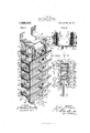
- Figure 1 is a perspective view of a complete switch board or mounting, one of the switch covering plates being removed.
- Fig. 2 is a cross sectional view, indicated by the sectionline Il. Il. of Figl.
- Fig. 3 is a diagram showing the relative arrangement and wiring ⁇ for the circuits.
- the insulating' bases 2 ,and 43 of suitable insulating material are mounted in any convenient manner and preferably connected by endmost bracglgets 4l, one at each end, whereby the board may be mounted upon any supporting frame or wall.
- the bases 2, 3 ⁇ confront each other, extending edgewise outwardly from the wall .or other support, .or from the back surface of an inclosing cabinet, if used.
- switches A, B, C Located between the bases 2, 3, and for the purpose of connecting ⁇ the bus bars 8 and 10 are switches A, B, C, each having one of its terminals 15 connected to bus bar 8 by bolt 18 andthe opposite terminal 16 connected to bus bar 10 by bolt 19.
- the terminals 20 of the same switches are connected to fuse contacts 25 by wire 28 ormay be connected directly by bolts, if desired, while the opposite terminals 21 are connected to fuse contacts l27 by wire 29, or otherwise.
- Said switches are of well-known construction and operation, having contact making and breaking ⁇ blades operable by the usual push buttons a, Z), respectively.
- the other terminals 20 of said switch are connected to the fuse contacts 26 by wire 28, and the opposite terminals 21 of the same switches are connected to fuse contacts 27 by wire 29.
- Guter fuse contacts 30, 3l and 32 are spaced beyond fuse contacts 25, 2G and and are each provided with a suitabh-i branch circuit terminal binds ing post 3?.
- fuse contacts 25--80, 2(3-31, and 27--32 are inserted the usual fuses 36.
- Said fuse contacts and their fuses are mounted on the opposite outer sides of bases 23, as shown, the wiring being indicated in the diagram Fig. 3.
- numerals a0, ll1 and t2 represent the feeders connected to the bus bars 8, 9 and 10 by bolts 45, 46, ll?, or in any other suitable manner. ln said diagram l show one switch wired to a lamp circuit which will be suilicient to give an understanding of the circuit wiring and connections.
- the circuit will be from plus or minus bus bar 10 through bolt 19 of switch F to terminal 16, blade 5() to terminal 20, to wire 28', to fuse clip 26, fuse 36 to clip 31, to branch terminal binding p etV 33, by wire 57, through lamps 56 and wire 55 to binding post 33 to fuse clip 32, fuse 36, fuse clip 27, to wire 29 to switch terminal 21, through blade 51, to terminal 15 and bolt 18 to bus bar 9.
- Similar connections through the other switches, bus bars and fuses to a lamp circuit will be readily understood without further description.
- the construction and operation of the in vention will be readily understood from the foregoing description.
- the switches intervening between the bases 2, 3, are preferably covered by a. suitable face plate lA for each switch, whereby the switches and the fuses are concealed.
- the bases being mounted face-wise with relation to each other, provide ample space for location of the several parts Very economically, and admit of the wiring connections being easily made with readiness of access throughout.
- the combination 0f a pair of confronting insulating bases forming side wall 11'1embers,'bus bars on the inner faces thereof, witches arranged between said bases connected to said bus bars, and cover plates for the switches lying across the edges of Said bases.
- a switch. board or mounting of the class described the combination of a pair of insulating bases arranged face-wise and forming side wall members, bus bars mounted on the inner side of said bases, switches arranged between said bases connected to said bus bars, and circuit conducting devices mounted on the outer side of .said bases and connected with the bus bars, substantially as set forth.
- a switch board or mounting of the class described the combination of a pair of insulating bases arranged face-wise to each other and forming side walls, a bus bar mounted on the inner side of one of said bases, a plurality of bus bars in alinement on the other of said bases confronting and parallel with said bus bar, and switches are ranged between said bases and connected to said bus bars.
- a switch board or mounting of the class described the combination of .a pair of insulating bases, a positive and a negative bus bar arranged in alinement on the inner side of one of said bases, a neutral bus bar similarly arranged on the other of said bases, switches arranged between said bases connected to said bus bars, and outermost fuse devices and connections connected with said switches, substantially as set forth.
- G. lnv a switch board or mounting of the class described, the combination of a pair of insulating bases arranged parallel and facewise to each other and forming side wall members, a plurality of bus bars secured to the inner faces of said bases, a plurality of fuse devices on the outer side of each of said bases connected with said bus bars, switches mounted on said bus bars and connecting the same between the bases, connecting end plates for the bases providing wall attaching means, the successively arranged ter- Clt 'ininals of the ⁇ fuse devices being adapted to connect "one pole of each circuit, substantially gas set forth.
- a switch board or mounting of the class described provided with a pair of insulating bases or panels parallel with and face-wise to each other and forming side wall members, a plurality of bus bars mounted on the inner sides thereof, switches arranged between said bases and connected to said bus bars, and a plurality of fuse devices on the outer sides thereof, said fuse devices being arranged on the said panels adjacently and successively, the adjacent and successive fuse devices being adapted to have the saine polarity, substantially as set forth.
- a switch board or mounting of the class described the combination of a plurality of bus bars, a plurality of fuse de vices, a base intervening between said bus bars and fuse devices, a bus bar confronting and parallel with said bus bars, a corresponding plurality of fuse devices arranged on a plane parallel with said iirst named fuse devices, a base intervening bet'veen said bus bar and fuse devices, and confronting said first-named base, switches mounted between said bases and connecting ⁇ said bus bars and fuse devices, substantially as set forth.
- a switch board or mounting of the class described the combination of a pair of face-to-face insulating panels connected to a pair of terminal panel brackets forining a rectangular inclosing frame, a plurality of bus bars and a plurality of connected switches supported upon and between said panels respectively, the said bus bars being arranged between the said switches and the said insulator panels at each side of the switches, the terminals of said switches having established connections to said bus bars, substantially as set forth.
- a switch board or mounting of the class described the combination of two faceeto-face insulating panels connected to two L-shaped terminal panel brackets forming a rectangular inclosing frame, said panel brackets having suitable openings between the panels, bus bars supported on the inner faces of said insulator panels, switches between and connecting said bus bars, a plurality of fuse devices having branch circuit terminals supported on the outside of said insulator panels in a difsaid bus bars and to said fuse devices, substantially as set forth.
- the combination of lonlgitudinal panels and panel brackets forming a frame, a plus and a minus bus bar arranged in alineinent on the inner face of one of said longitudinal panels, a neutral bus bar arranged on vthe inner face of the other of said longitudinal panels, branch circuit switches mounted on the bus bars between and adjacent to the inner faces of said longitudinal panels, a ,plurality of fuse devices arranged on each of said longitu* dinal panels in a diiferent plane from said bus bars, said branch circuit switches being connected to said bus bars and to said fuse devices.
- a switch board of the class described the combination of longitudinal insulator panels connected to a pair of endmost connecting panel brackets forming a frame, a plurality of bus bars arranged within said frame comprising a plus, a minus, and a neutral bar respectively, means for supporting theni on the inner confronting faces of the panels, a plurality of switches mounted on the said bus bars and adjacent to the inner faces of said insulator panels, a plurality of fuse devices arranged on the outer sides of said insulator panels, means for supporting them, said switches being connected to said bus bars and to said fuse devices, each of the said switches and bus bars intervening between a pair of said fuse devices and adapted to be connected in a circuit in series therewith, and a cover for each switch and each pair of fuse devices extending across the front edges of the panels.
- a switch board of the -class described the combination of a pair of insulating bases or panels arranged face-wise to each other, a pair of connecting panel brackets covering the ends of the panels and forming a frame, a plurality of bus bars of plus, minus, and neutral polarity said switches having established connections to CIL respectively, a plurality of branch circuit by and between the panels forming saidI i'rzune, said bus bers being arranged acljak cent to seid switches and on the inner faces of said insulator panels and covered thereby, each of the said switches, bus bars, and the said insulator' panels intervening between the respective branch circuits in series with said bus bars and said switch, and
Landscapes
- Physics & Mathematics (AREA)
- Electromagnetism (AREA)
- Engineering & Computer Science (AREA)
- Power Engineering (AREA)
- Switch Cases, Indication, And Locking (AREA)
Description
1. P. HAYES.
SWITCH BOARD 0R MOUNTING.
APPLICATloN FILED ocT. 5. 1914.v
1 28,362. Patented May 29, 1917.
FIGA- t l v FH12.A
WITNESSES 3 UNITED sTATn-s PATENT oPPIon.
roIIN P. IIAYES, or PITTSBURGH, PENNSYLVANIA, AssIcNon or oNE-IIALPy To JOHN n. BARNHART, or PITTSBURGH, PENNSYLVANIA.
SWITCH BOARD 0R MOUNTING.
Specification of Letters Patent.
Patented May 29, 1917.
Application led October 5, 1914. Serial No. 865,006.
electric switch boards or mountings adapt! ed to carry or support the elements necessary for receiving or distribution of elec- I trical circuits.
The objects yin view are to construct such an apparatnsin a simple, compact and readily available form, providing ample room and .capacity .tor attachments and connections of the variousv conductor elements, with economy of material and space.
To mount the elements on bases or boards so as to eliminate the bus bars and the conductor parts from the face thereof.
To reduce the Vamount of copper and insulating material and to so arrange the switches Aas to act cooperatively with the main bus bars and to eliminate sub bus bars between the main bus bars and the branch circuit terminals.
To arrange the lfuse devices adjacently and successively so as to be of the same polarity.
To mount the switches between panels and on 'the bus bars and to arrange the `l'use attachments on the outer sides of said panels so that a terminal pole of each of the various circuits will have a terminal pole on each of the panels.
Such an arrangement enables me to arrange the switches and fuse devices in such a manner as to utilize all the available space of the bus bars and the insulator panels and also, in such an arrangement, to arrange front plates covering all the conductor parts so that persons operating the switches will not come into contact therewith.
In a two wire distribution of a three wire l system, I preferably arrange the plus (-1-) and minus bars in the same line, and the neutral (i) bus bars parallel to the plus and minus bus bars. In such arrange ment,`and with the arrangement of the baseboards, switches and fuse devices as hereinafter described, it will be seen that there is resulting general economy in regard to material, workmanship, space and eiliciency, due to the reduction of the number of conductor-joints and the shortening of space between the bus bars andthe branch circuit terminals.
The switch board or mounting, per 8c, is compactly constructed in a simplemanner and all parts are easy of'afccessa in case of derangement.
-ln the accompanying drawings showing preferred constructions or adaptations of the inventionfd I Figure 1 is a perspective view of a complete switch board or mounting, one of the switch covering plates being removed.
Fig. 2 is a cross sectional view, indicated by the sectionline Il. Il. of Figl.
Fig. 3 is a diagram showing the relative arrangement and wiring` for the circuits.
leierring to' the drawings, the insulating' bases 2 ,and 43 of suitable insulating material, are mounted in any convenient manner and preferably connected by endmost bracglgets 4l, one at each end, whereby the board may be mounted upon any supporting frame or wall. As thus arranged, the bases 2, 3 `confront each other, extending edgewise outwardly from the wall .or other support, .or from the back surface of an inclosing cabinet, if used. p
Arranged along` the inner Vface 4of one of the insulating bases 2, arevthe bus barsB, 9, or' diiferent polarity.` as indicated by the signs and respectively; On thejinner side of the opposite base 3, opposite bus bars b5k and 9 and parallel therewith, isthe neutral bus bar 1 0, its polarity being indicated by the plus or minus sign i.
Located between the bases 2, 3, and for the purpose of connecting` the bus bars 8 and 10 are switches A, B, C, each having one of its terminals 15 connected to bus bar 8 by bolt 18 andthe opposite terminal 16 connected to bus bar 10 by bolt 19. The terminals 20 of the same switches are connected to fuse contacts 25 by wire 28 ormay be connected directly by bolts, if desired, while the opposite terminals 21 are connected to fuse contacts l27 by wire 29, or otherwise.
Said switches are of well-known construction and operation, having contact making and breaking` blades operable by the usual push buttons a, Z), respectively.
`Similar switches l), E, F, are mounted between the bases 2, 3, in a like manner, connecting bus bars 9 and 10, as shown, each having one of its terminals 15 connected to bus bar 9 by bolts 18 and its other terminal 16 connected to bus bar 10 by bolt 19.
The other terminals 20 of said switch are connected to the fuse contacts 26 by wire 28, and the opposite terminals 21 of the same switches are connected to fuse contacts 27 by wire 29. Guter fuse contacts 30, 3l and 32 are spaced beyond fuse contacts 25, 2G and and are each provided with a suitabh-i branch circuit terminal binds ing post 3?. Between fuse contacts 25--80, 2(3-31, and 27--32 are inserted the usual fuses 36. Said fuse contacts and their fuses are mounted on the opposite outer sides of bases 23, as shown, the wiring being indicated in the diagram Fig. 3.
Referring to such diagram, numerals a0, ll1 and t2 represent the feeders connected to the bus bars 8, 9 and 10 by bolts 45, 46, ll?, or in any other suitable manner. ln said diagram l show one switch wired to a lamp circuit which will be suilicient to give an understanding of the circuit wiring and connections.
Assuming the bus bars to be energized by the feeders 40, 41, 112, from a suitable source, the circuit will be from plus or minus bus bar 10 through bolt 19 of switch F to terminal 16, blade 5() to terminal 20, to wire 28', to fuse clip 26, fuse 36 to clip 31, to branch terminal binding p etV 33, by wire 57, through lamps 56 and wire 55 to binding post 33 to fuse clip 32, fuse 36, fuse clip 27, to wire 29 to switch terminal 21, through blade 51, to terminal 15 and bolt 18 to bus bar 9. Similar connections through the other switches, bus bars and fuses to a lamp circuit will be readily understood without further description.
The construction and operation of the in vention will be readily understood from the foregoing description. The switches intervening between the bases 2, 3, are preferably covered by a. suitable face plate lA for each switch, whereby the switches and the fuses are concealed.
lt will be understood, of course, that any suitable type or construction. of switch other than the push button type may be substitutcd therefor and used with equally good results.
The bases, being mounted face-wise with relation to each other, provide ample space for location of the several parts Very economically, and admit of the wiring connections being easily made with readiness of access throughout.
It will be understood that the construction may be greatly Varied, changed or modified in size or other details by the skilled electrician, but. that all such changes are to be considered as within the scope of the following claims.
lihat l claim is:
1. In a switch board or mounting of the class described, the combination 0f a pair of confronting insulating bases forming side wall 11'1embers,'bus bars on the inner faces thereof, witches arranged between said bases connected to said bus bars, and cover plates for the switches lying across the edges of Said bases.
2. ln a switch. board or mounting of the class described, the combination of a pair of insulating bases arranged face-wise and forming side wall members, bus bars mounted on the inner side of said bases, switches arranged between said bases connected to said bus bars, and circuit conducting devices mounted on the outer side of .said bases and connected with the bus bars, substantially as set forth.
3. ln a switch board or mounting of the class described, the combination of a pair of insulating bases arranged face-wise to each other and forming side walls, a bus bar mounted on the inner side of one of said bases, a plurality of bus bars in alinement on the other of said bases confronting and parallel with said bus bar, and switches are ranged between said bases and connected to said bus bars.
4l. ln a switch board or mounting Of the class described, the combination of a pair of insulating bases, a positive and a negative bus bar arranged in alinement on the inner side of one of said bases, a neutral bus bar similarly arranged on the other of said bases, and switches arranged between said bases connected to said bus bars, substantially as set forth.
5. ln a switch board or mounting of the class described, the combination of .a pair of insulating bases, a positive and a negative bus bar arranged in alinement on the inner side of one of said bases, a neutral bus bar similarly arranged on the other of said bases, switches arranged between said bases connected to said bus bars, and outermost fuse devices and connections connected with said switches, substantially as set forth.
G. lnv a switch board or mounting of the class described, the combination of a pair of insulating bases arranged parallel and facewise to each other and forming side wall members, a plurality of bus bars secured to the inner faces of said bases, a plurality of fuse devices on the outer side of each of said bases connected with said bus bars, switches mounted on said bus bars and connecting the same between the bases, connecting end plates for the bases providing wall attaching means, the successively arranged ter- Clt 'ininals of the `fuse devices being adapted to connect "one pole of each circuit, substantially gas set forth.
7 In a switch board or mounting of the class described, the combination of a pair of parallel insulating bases arranged face-wise, a minus and plus bus bar supported on the inner side of one of said bases, a neutral bus bar supported on the inner sideof theother of said. bases, switches mounted on the bus bars and connecting them, and connections .from the bus bars to the fuse devices.
8. ln a switch board or mounting of the class described provided with a pair of insulating bases or panels parallel with and face-wise to each other and forming side wall members, a plurality of bus bars mounted on the inner sides thereof, switches arranged between said bases and connected to said bus bars, and a plurality of fuse devices on the outer sides thereof, said fuse devices being arranged on the said panels adjacently and successively, the adjacent and successive fuse devices being adapted to have the saine polarity, substantially as set forth.
9. ln a switch board or mounting of the class described, the combination of a plurality of bus bars, a plurality of fuse de vices, a base intervening between said bus bars and fuse devices, a bus bar confronting and parallel with said bus bars, a corresponding plurality of fuse devices arranged on a plane parallel with said iirst named fuse devices, a base intervening bet'veen said bus bar and fuse devices, and confronting said first-named base, switches mounted between said bases and connecting` said bus bars and fuse devices, substantially as set forth.
l0. In a switch board or mounting of the class described, the combination of a pair of face-to-face insulating panels connected to a pair of terminal panel brackets forining a rectangular inclosing frame, a plurality of bus bars and a plurality of connected switches supported upon and between said panels respectively, the said bus bars being arranged between the said switches and the said insulator panels at each side of the switches, the terminals of said switches having established connections to said bus bars, substantially as set forth.
ll. In a switch board or mounting of the class described, the combination of two faceeto-face insulating panels connected to two L-shaped terminal panel brackets forming a rectangular inclosing frame, said panel brackets having suitable openings between the panels, bus bars supported on the inner faces of said insulator panels, switches between and connecting said bus bars, a plurality of fuse devices having branch circuit terminals supported on the outside of said insulator panels in a difsaid bus bars and to said fuse devices, substantially as set forth.
l2. in aswitch board or mounting of the vclass described, the combination of a pair of insulator panels connected to a pair of 4endmost panel brackets forming a rectangular frame, a plus and a minus bus bar arranged in `alinement on `the inner face of one of said insulator panels, a neutral bus bar arranged on the inner face of the other of said panels, switches arranged within said panels mounted on and connected to said bus'bars, and terminal connecting devices for making connection with branch circuits beyond said bus bars.
13. In a switch board or mounting of the class described, the combination of lonlgitudinal panels and panel brackets forming a frame, a plus and a minus bus bar arranged in alineinent on the inner face of one of said longitudinal panels, a neutral bus bar arranged on vthe inner face of the other of said longitudinal panels, branch circuit switches mounted on the bus bars between and adjacent to the inner faces of said longitudinal panels, a ,plurality of fuse devices arranged on each of said longitu* dinal panels in a diiferent plane from said bus bars, said branch circuit switches being connected to said bus bars and to said fuse devices.
14.-. in a switch board of the class described, the combination of longitudinal insulator panels connected to a pair of endmost connecting panel brackets forming a frame, a plurality of bus bars arranged within said frame comprising a plus, a minus, and a neutral bar respectively, means for supporting theni on the inner confronting faces of the panels, a plurality of switches mounted on the said bus bars and adjacent to the inner faces of said insulator panels, a plurality of fuse devices arranged on the outer sides of said insulator panels, means for supporting them, said switches being connected to said bus bars and to said fuse devices, each of the said switches and bus bars intervening between a pair of said fuse devices and adapted to be connected in a circuit in series therewith, and a cover for each switch and each pair of fuse devices extending across the front edges of the panels.
15. In a switch board of the -class described, the combination of a pair of insulating bases or panels arranged face-wise to each other, a pair of connecting panel brackets covering the ends of the panels and forming a frame, a plurality of bus bars of plus, minus, and neutral polarity said switches having established connections to CIL respectively, a plurality of branch circuit by and between the panels forming saidI i'rzune, said bus bers being arranged acljak cent to seid switches and on the inner faces of said insulator panels and covered thereby, each of the said switches, bus bars, and the said insulator' panels intervening between the respective branch circuits in series with said bus bars and said switch, and
a cover Jfor each of said switches and for' said respective branch circuit terminals eX- tencling across the Jfront edges of the panels.
n testimony whereof I hereunto ai'iix my signature in the presence of two witnesses.
JOHN P. HAYES.
lVitnesses:
C. M. CLARKE, FREDK STAUB.
Copies of this patent may be obtained for five cents each, by addressing; the Commissioner of Patents, Washington, D. C.
Priority Applications (1)
| Application Number | Priority Date | Filing Date | Title |
|---|---|---|---|
| US86500614A US1228362A (en) | 1914-10-05 | 1914-10-05 | Switch board or mounting. |
Applications Claiming Priority (1)
| Application Number | Priority Date | Filing Date | Title |
|---|---|---|---|
| US86500614A US1228362A (en) | 1914-10-05 | 1914-10-05 | Switch board or mounting. |
Publications (1)
| Publication Number | Publication Date |
|---|---|
| US1228362A true US1228362A (en) | 1917-05-29 |
Family
ID=3296209
Family Applications (1)
| Application Number | Title | Priority Date | Filing Date |
|---|---|---|---|
| US86500614A Expired - Lifetime US1228362A (en) | 1914-10-05 | 1914-10-05 | Switch board or mounting. |
Country Status (1)
| Country | Link |
|---|---|
| US (1) | US1228362A (en) |
Cited By (2)
| Publication number | Priority date | Publication date | Assignee | Title |
|---|---|---|---|---|
| US2553667A (en) * | 1948-03-15 | 1951-05-22 | Cutler Hammer Inc | Supporting panel for groups of electrical devices |
| US3088055A (en) * | 1959-04-20 | 1963-04-30 | Allan H Schwing | Panel board chassis and wiring channel |
-
1914
- 1914-10-05 US US86500614A patent/US1228362A/en not_active Expired - Lifetime
Cited By (2)
| Publication number | Priority date | Publication date | Assignee | Title |
|---|---|---|---|---|
| US2553667A (en) * | 1948-03-15 | 1951-05-22 | Cutler Hammer Inc | Supporting panel for groups of electrical devices |
| US3088055A (en) * | 1959-04-20 | 1963-04-30 | Allan H Schwing | Panel board chassis and wiring channel |
Similar Documents
| Publication | Publication Date | Title |
|---|---|---|
| ATE250812T1 (en) | POWER RAIL ARRANGEMENT FOR AN ELECTRICAL SWITCH PANEL | |
| US3192446A (en) | Distribution panel | |
| US1228362A (en) | Switch board or mounting. | |
| US2901547A (en) | Switching system network | |
| US3243663A (en) | Circuit breaker panel board | |
| US2999190A (en) | Switchboard | |
| US2897410A (en) | Plug-in type circuit breaker panelboard | |
| US977123A (en) | Panel-board. | |
| US2358346A (en) | Feed unit for electric wiring systems | |
| US1744209A (en) | Electrical panel board | |
| US3437985A (en) | Flexible bus-bar clamp | |
| US1234471A (en) | Switchboard. | |
| US756966A (en) | Panel-board for electric distribution. | |
| US1230403A (en) | Changeable electric sign. | |
| US1162788A (en) | Grid resistance. | |
| GB2312797A (en) | An electrical-energy distribution board | |
| US931464A (en) | Metering panel-board. | |
| US690928A (en) | Lamp-socket. | |
| US796475A (en) | Illuminated sign. | |
| US3201657A (en) | Panelboard for bolted and plug-in circuit breaker | |
| US660113A (en) | Panel-board and fuse-holder. | |
| US1132355A (en) | System of electrical wiring. | |
| US737283A (en) | Fuse-block. | |
| US717194A (en) | Arc-light switchboard. | |
| US1036508A (en) | Connection device for circuit-conductors. |