US12276961B2 - Wireless control assembly for cutting machine - Google Patents
Wireless control assembly for cutting machine Download PDFInfo
- Publication number
- US12276961B2 US12276961B2 US18/036,324 US202118036324A US12276961B2 US 12276961 B2 US12276961 B2 US 12276961B2 US 202118036324 A US202118036324 A US 202118036324A US 12276961 B2 US12276961 B2 US 12276961B2
- Authority
- US
- United States
- Prior art keywords
- recited
- machine controller
- post assembly
- tool
- tool post
- Prior art date
- Legal status (The legal status is an assumption and is not a legal conclusion. Google has not performed a legal analysis and makes no representation as to the accuracy of the status listed.)
- Active, expires
Links
Images


Classifications
-
- G—PHYSICS
- G05—CONTROLLING; REGULATING
- G05B—CONTROL OR REGULATING SYSTEMS IN GENERAL; FUNCTIONAL ELEMENTS OF SUCH SYSTEMS; MONITORING OR TESTING ARRANGEMENTS FOR SUCH SYSTEMS OR ELEMENTS
- G05B19/00—Program-control systems
- G05B19/02—Program-control systems electric
- G05B19/18—Numerical control [NC], i.e. automatically operating machines, in particular machine tools, e.g. in a manufacturing environment, so as to execute positioning, movement or co-ordinated operations by means of program data in numerical form
- G05B19/19—Numerical control [NC], i.e. automatically operating machines, in particular machine tools, e.g. in a manufacturing environment, so as to execute positioning, movement or co-ordinated operations by means of program data in numerical form characterised by positioning or contouring control systems, e.g. to control position from one programmed point to another or to control movement along a programmed continuous path
- G05B19/40—Open loop systems, e.g. using stepping motor
-
- B—PERFORMING OPERATIONS; TRANSPORTING
- B23—MACHINE TOOLS; METAL-WORKING NOT OTHERWISE PROVIDED FOR
- B23B—TURNING; BORING
- B23B3/00—General-purpose turning-machines or devices, e.g. centre lathes with feed rod and lead screw; Sets of turning-machines
- B23B3/22—Turning-machines or devices with rotary tool heads
- B23B3/26—Turning-machines or devices with rotary tool heads the tools of which perform a radial movement; Rotary tool heads thereof
- B23B3/265—Surfacing or grooving flanges
-
- G—PHYSICS
- G05—CONTROLLING; REGULATING
- G05B—CONTROL OR REGULATING SYSTEMS IN GENERAL; FUNCTIONAL ELEMENTS OF SUCH SYSTEMS; MONITORING OR TESTING ARRANGEMENTS FOR SUCH SYSTEMS OR ELEMENTS
- G05B19/00—Program-control systems
- G05B19/02—Program-control systems electric
- G05B19/18—Numerical control [NC], i.e. automatically operating machines, in particular machine tools, e.g. in a manufacturing environment, so as to execute positioning, movement or co-ordinated operations by means of program data in numerical form
- G05B19/409—Numerical control [NC], i.e. automatically operating machines, in particular machine tools, e.g. in a manufacturing environment, so as to execute positioning, movement or co-ordinated operations by means of program data in numerical form characterised by using manual data input [MDI] or by using control panel, e.g. controlling functions with the panel; characterised by control panel details or by setting parameters
-
- G—PHYSICS
- G05—CONTROLLING; REGULATING
- G05B—CONTROL OR REGULATING SYSTEMS IN GENERAL; FUNCTIONAL ELEMENTS OF SUCH SYSTEMS; MONITORING OR TESTING ARRANGEMENTS FOR SUCH SYSTEMS OR ELEMENTS
- G05B2219/00—Program-control systems
- G05B2219/30—Nc systems
- G05B2219/31—From computer integrated manufacturing till monitoring
- G05B2219/31165—Control handover in wireless automation networks
-
- G—PHYSICS
- G05—CONTROLLING; REGULATING
- G05B—CONTROL OR REGULATING SYSTEMS IN GENERAL; FUNCTIONAL ELEMENTS OF SUCH SYSTEMS; MONITORING OR TESTING ARRANGEMENTS FOR SUCH SYSTEMS OR ELEMENTS
- G05B2219/00—Program-control systems
- G05B2219/30—Nc systems
- G05B2219/33—Director till display
- G05B2219/33192—Radio link, wireless
-
- G—PHYSICS
- G05—CONTROLLING; REGULATING
- G05B—CONTROL OR REGULATING SYSTEMS IN GENERAL; FUNCTIONAL ELEMENTS OF SUCH SYSTEMS; MONITORING OR TESTING ARRANGEMENTS FOR SUCH SYSTEMS OR ELEMENTS
- G05B2219/00—Program-control systems
- G05B2219/30—Nc systems
- G05B2219/37—Measurements
- G05B2219/37358—Depth of cut
Definitions
- a system and methodology are provided for enabling wireless control of a machine tool, e.g. a portable machine tool used on-site.
- a motor e.g. a stepper motor
- the motor is coupled with a machine controller, and the tool post assembly is mounted proximate an object to be machined.
- the object may be machined via a cutting tool mounted to a cutter post of the tool post assembly.
- the machine controller operates to control movement of the cutter post along a desired axis during the cutting operation.
- the machine controller and thus the cutting operation are controlled wirelessly according to instructions provided via a control device, e.g. a handheld control device, which is placed in wireless communication with the machine controller.
- FIG. 1 is an illustration of an example of a wireless control system for use in controlling a machine in accordance with embodiments of the present disclosure
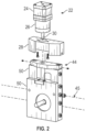
- FIG. 2 is an exploded view of an example of a tool post assembly which may be coupled with a stepper motor via a gearbox and a mounting bracket in accordance with embodiments of the present disclosure;
- FIG. 3 is an orthogonal view of an example of a machine controller coupled with a stepper motor via a connection lead in accordance with embodiments of the present disclosure
- FIG. 4 is an exploded view of an example of a machine controller in accordance with embodiments of the present disclosure
- FIG. 5 is a schematic example of a graphical user interface which may be used on a handheld device for wirelessly providing instructions to the machine controller in accordance with embodiments of the present disclosure
- FIG. 6 is a schematic example of another screen of the graphical user interface in accordance with embodiments of the present disclosure.
- FIG. 7 is a schematic example of another screen of the graphical user interface in accordance with embodiments of the present disclosure.
- FIG. 8 is a schematic example of another screen of the graphical user interface in accordance with embodiments of the present disclosure.
- connection As used herein, the terms “connect”, “connection”, “connected”, “in connection with”, and “connecting” are used to mean “in direct connection with” or “in connection with via one or more elements”; and the term “set” is used to mean “one element” or “more than one element”. Further, the terms “couple”, “coupling”, “coupled”, “coupled together”, and “coupled with” are used to mean “directly coupled together” or “coupled together via one or more elements”. As used herein, the terms “up” and “down”; “upper” and “lower”; “top” and “bottom”; and other like terms indicating relative positions to a given point or element are utilized to more clearly describe some elements.
- the present disclosure generally relates to a system and methodology for providing wireless control of a machine tool, e.g. a portable machine tool used on-site.
- a motor e.g. a stepper motor
- a tool post assembly which is used to control the movement of a tool, e.g. a cutting tool, along at least one axis.
- the motor may be connected with the tool post assembly via a gearbox. Additionally, the motor is coupled with a machine controller, and the tool post assembly is mounted proximate an object to be machined.
- the object may be machined via a cutting tool mounted to a cutter post of the tool post assembly.
- One type of application may involve the refacing of a flange associated with a pipe or other structure.
- the machine controller operates to control movement of the cutter post along a desired axis during the cutting operation.
- the machine controller may be operated to control cutting depth along a linear cutting depth axis.
- the machine controller and thus the cutting operation are controlled wirelessly according to control instructions provided via a control device, e.g. a handheld control device, which is placed in wireless communication with the machine controller.
- a control device e.g. a handheld control device, which is placed in wireless communication with the machine controller.
- an operator may provide control instructions to the handheld control device via a graphical user interface.
- control instructions may then be wirelessly relayed to the machine controller which, in turn, controls operation of the tool post assembly/cutting tool according to the inputs provided. Accordingly, an operator may control the feed along a given axis or provide other machining controls without physically interacting with the tool post assembly or cutting tool during the cutting operation.
- the control scheme may be used for a variety of remote machine controls.
- the control system may be used for indexing of a rotational output which may be used to control the feed along an axis of the machine tool.
- the control system also may be used to enable system monitoring and interaction of safety protocols in the event of a signal loss. If the tool post assembly is used on-site with a lathe type cutter for refacing flanges, the flange being operated on may be held static while the lathe rotates within or outside the flange.
- the wireless system enables cut depth controls to be sent to the machine controller, thus allowing an operator to remain at a distance while controlling the cutting operation.
- the wireless control system 20 comprises a motive unit 22 having, for example, a motor 24 coupled to a gearbox 26 secured to a mounting bracket 28 .
- the motor 24 may be in the form of a stepper motor or other suitable motor providing a rotational output to gearbox 26 which, in turn, provides a rotational output via output shaft 30 .
- a machine controller 32 e.g. a cut depth controller, is coupled with the stepper motor 24 (or other suitable motor) via a connection lead 34 which may be in the form of a cable or other suitable connection lead for transferring control commands from machine controller 32 to the motor 24 .
- the tool post assembly 44 may have a variety of configurations depending on the machining operation or other operation to be performed on object 45 .
- the tool post assembly 44 may have a variety of gears, shafts, and/or mounting brackets configured to accommodate the intended machining operation or other operation on object 45 .
- the tool post assembly 44 may have an output shaft/gear and appropriate mounting features for mounting and driving the tool post assembly 44 linearly along a supporting tool post structure.
- the tool post assembly 44 may have cooperating components 50 (see FIG. 2 ) which enable mounting, positioning, and precisely controlled movement of tool 48 along a desired axis in response to operation of stepper motor 24 .
- cutting tool 48 is in the form of a lathe and the tool post assembly 44 is constructed as a portable unit which may be mounted on or adjacent object which, in this example, is in the form of a metal flange in need of refacing.
- the cooperating components 50 may be in the form of components which can slide or shift relative to each other to enable control over the depth of cut based on inputs from stepper motor 44 .
- the machine controller 32 provides signals to stepper motor 24 via connection lead 34 to precisely control the stepper motor 24 for achieving a desired depth of cut.
- an operator is able to select and adjust the control signals output by machine controller 32 according to instructions provided remotely via handheld device 36 . These control instructions are sent wirelessly from handheld device 36 to the machine controller 32 which then converts them into appropriate control commands for stepper motor 24 so as to precisely control the depth of cut on the flange or other object 45 .
- machine controller 32 which is able to wirelessly receive control commands/instructions from handheld device 36 and to wirelessly output data to the handheld device 36 .
- machine controller 32 comprises a stepper motor controller 52 configured for providing the machine control commands to stepper motor 24 .
- the stepper motor controller 52 may be mounted in a housing 54 .
- the machine controller 32 comprises a microcontroller 56 having a wireless transceiver 58 able to receive the wireless commands/instructions from handheld device 36 and to output data to handheld device 36 .
- the microcontroller 56 also is mounted within housing 54 .
- the machine controller 32 also comprises a battery pack or other self-contained power source for powering controllers 52 , 56 .
- the battery pack 60 may be a rechargeable battery pack which is also mounted within housing 54 and closed in via a suitable housing cover 62 .
- the operator interface 38 and corresponding control software and wireless communication software may have a variety of configurations suitable for use on handheld device 36 .
- FIGS. 5 - 8 examples of functionality that may be provided via operator interface 38 are shown although many other types of graphical user interfaces and many other types of control functionality may be implemented.
- the operator interface 38 provides a startup screen having a screen header 64 which may comprise screen navigation buttons and a battery status monitor. Additionally, the operator interface 38 provides data entry and display fields 66 through which control data may be entered, e.g. cut depth and other cutting related data.
- the illustrated operator interface 38 also comprises main control buttons 68 . Examples of main control buttons 68 include a start button which initiates movement of the cutting tool 48 ; a cut tool direction button (e.g. cutting tool in or cutting tool out); and an enable/disable button for selectively enabling the machine controller 32 .
- a settings screen of the operator interface 38 is illustrated.
- the settings screen may be used to provide various data/information 70 to the operator. Examples of such information include gearbox ratio, metric/imperial units, stepper motor pulse/revolution data, distance traveled data, speed data, and/or other desired data.
- the operator interface 38 also may be used to provide a device information screen 72 , as illustrated in FIG. 7 . Such a screen may be used to provide wireless interface data, project data, system power data, specific application data, and/or other desired data that may be useful to an operator.
- FIG. 8 another screen example of operator interface 38 is illustrated.
- the screen may be used to output customer data 74 and cutting history data 76 .
- the operator interface 38 may be configured for enabling many types of command/instruction entry and for providing many types of data related to a given cutting operation or other operation.
- the configuration and use of overall wireless control system 20 may be adjusted.
- the wireless control system may utilize various wireless interfaces for use between handheld device 36 and machine controller 32 .
- various types of machine controllers 32 may be utilized according to the type of machine being controlled and the desired control functionality.
- the tool post assembly 44 and the cutting tool 48 (or other type of tool) may be constructed and selected according to a variety of machining operations. Regardless of the specifics of the operation, however, the wireless control system 20 enables an operator to remotely control a desired operation on object 45 .
Landscapes
- Engineering & Computer Science (AREA)
- Human Computer Interaction (AREA)
- Manufacturing & Machinery (AREA)
- Physics & Mathematics (AREA)
- General Physics & Mathematics (AREA)
- Automation & Control Theory (AREA)
- Numerical Control (AREA)
- Milling, Drilling, And Turning Of Wood (AREA)
Abstract
Description
Claims (20)
Priority Applications (1)
| Application Number | Priority Date | Filing Date | Title |
|---|---|---|---|
| US18/036,324 US12276961B2 (en) | 2020-12-15 | 2021-12-14 | Wireless control assembly for cutting machine |
Applications Claiming Priority (3)
| Application Number | Priority Date | Filing Date | Title |
|---|---|---|---|
| US202063125624P | 2020-12-15 | 2020-12-15 | |
| US18/036,324 US12276961B2 (en) | 2020-12-15 | 2021-12-14 | Wireless control assembly for cutting machine |
| PCT/US2021/063395 WO2022132824A1 (en) | 2020-12-15 | 2021-12-14 | Wireless control assembly for cutting machine |
Publications (2)
| Publication Number | Publication Date |
|---|---|
| US20240012380A1 US20240012380A1 (en) | 2024-01-11 |
| US12276961B2 true US12276961B2 (en) | 2025-04-15 |
Family
ID=82058562
Family Applications (1)
| Application Number | Title | Priority Date | Filing Date |
|---|---|---|---|
| US18/036,324 Active 2042-01-11 US12276961B2 (en) | 2020-12-15 | 2021-12-14 | Wireless control assembly for cutting machine |
Country Status (4)
| Country | Link |
|---|---|
| US (1) | US12276961B2 (en) |
| EP (1) | EP4263095A4 (en) |
| CA (1) | CA3199741A1 (en) |
| WO (1) | WO2022132824A1 (en) |
Citations (7)
| Publication number | Priority date | Publication date | Assignee | Title |
|---|---|---|---|---|
| US20090215598A1 (en) | 2008-02-26 | 2009-08-27 | Comau S.P.A. | Machining Unit, Particularly For Machining The Surface Of Cylindrical Cavities, Having A Tool Holding Assembly Including Actuating Means For Adjusting The Tool Position And A Wireless Control System For The Actuating Means |
| US20140069254A1 (en) | 2008-08-20 | 2014-03-13 | The Boeing Company | Method of Cutting a Slot |
| US20150151363A1 (en) | 2011-05-13 | 2015-06-04 | Furmanite Australia Pty. Ltd. | Surface machining apparatus |
| US20160288214A1 (en) | 2013-11-29 | 2016-10-06 | Murata Machinery, Ltd. | Machine tool and cutting method |
| US20160303696A1 (en) | 2013-12-04 | 2016-10-20 | Dcseng Co., Ltd. | Apparatus for processing circular or square tube or bar material to desired shape by freely controlling cutting tool by wireless communication |
| US9868182B1 (en) | 2017-05-16 | 2018-01-16 | Jeffery A. Smith | Safe mode cross slide system |
| US20200114436A1 (en) * | 2018-10-10 | 2020-04-16 | Mingye Song | Cnc sink aperture cutting machine and method |
-
2021
- 2021-12-14 CA CA3199741A patent/CA3199741A1/en active Pending
- 2021-12-14 WO PCT/US2021/063395 patent/WO2022132824A1/en not_active Ceased
- 2021-12-14 US US18/036,324 patent/US12276961B2/en active Active
- 2021-12-14 EP EP21907664.3A patent/EP4263095A4/en active Pending
Patent Citations (7)
| Publication number | Priority date | Publication date | Assignee | Title |
|---|---|---|---|---|
| US20090215598A1 (en) | 2008-02-26 | 2009-08-27 | Comau S.P.A. | Machining Unit, Particularly For Machining The Surface Of Cylindrical Cavities, Having A Tool Holding Assembly Including Actuating Means For Adjusting The Tool Position And A Wireless Control System For The Actuating Means |
| US20140069254A1 (en) | 2008-08-20 | 2014-03-13 | The Boeing Company | Method of Cutting a Slot |
| US20150151363A1 (en) | 2011-05-13 | 2015-06-04 | Furmanite Australia Pty. Ltd. | Surface machining apparatus |
| US20160288214A1 (en) | 2013-11-29 | 2016-10-06 | Murata Machinery, Ltd. | Machine tool and cutting method |
| US20160303696A1 (en) | 2013-12-04 | 2016-10-20 | Dcseng Co., Ltd. | Apparatus for processing circular or square tube or bar material to desired shape by freely controlling cutting tool by wireless communication |
| US9868182B1 (en) | 2017-05-16 | 2018-01-16 | Jeffery A. Smith | Safe mode cross slide system |
| US20200114436A1 (en) * | 2018-10-10 | 2020-04-16 | Mingye Song | Cnc sink aperture cutting machine and method |
Non-Patent Citations (2)
| Title |
|---|
| International Search Report and Written Opinion in related application PCT/US2021/063395 dated Mar. 7, 2022. |
| Office Action in related application EP 21907664.3 dated Feb. 14, 2025. |
Also Published As
| Publication number | Publication date |
|---|---|
| EP4263095A4 (en) | 2025-02-26 |
| WO2022132824A1 (en) | 2022-06-23 |
| CA3199741A1 (en) | 2022-06-23 |
| US20240012380A1 (en) | 2024-01-11 |
| EP4263095A1 (en) | 2023-10-25 |
Similar Documents
| Publication | Publication Date | Title |
|---|---|---|
| CN101898318B (en) | Robot control system provided in machining system including robot and machine tool | |
| US20090112362A1 (en) | Controller of work piece-conveying robot | |
| JP2008197856A (en) | Automatic machine system and control method thereof | |
| US20150151363A1 (en) | Surface machining apparatus | |
| US9649695B1 (en) | Automated cross slide system | |
| CN103481230A (en) | Tool and operation method thereof | |
| CN1990176B (en) | Turret servo control device with overriding and control method thereof | |
| JP2015069526A (en) | Display device | |
| US12276961B2 (en) | Wireless control assembly for cutting machine | |
| US9085039B1 (en) | Field portable pipe-mounted pipe cutting system with integral controls | |
| US10413971B1 (en) | Safe mode cross slide system | |
| US9868182B1 (en) | Safe mode cross slide system | |
| CN206169721U (en) | Tool magazine through arm swing tool changing | |
| US12493283B2 (en) | Machining center automatic operating system | |
| US11994841B2 (en) | System and method for controlling a core drill and an auto feed device with a human machine interface arranged on the core drill | |
| KR20230123782A (en) | Wireless communication control device and control method of detachable tool holder | |
| JP2008097193A (en) | Machine tool controller | |
| JP6130511B2 (en) | Machine tool and processing method thereof | |
| KR101494130B1 (en) | Controller of index table | |
| CN223630462U (en) | A pipe cutting machine that automatically reaches a designated area | |
| CN202210227U (en) | Pipe cutting machine numerical control device | |
| JP5061292B2 (en) | Electric tapping machine and its machining condition switching system | |
| US12365114B2 (en) | Method and system for establishing a connection between a machine tool and an auxiliary device and testing an emergency cutout functionality of the auxiliary device | |
| JP2002268716A (en) | Remote monitoring / control apparatus and method for NC processing apparatus and manual pulse handle used for the same | |
| US20050113944A1 (en) | Control method and system for machine tools and industrial vehicles |
Legal Events
| Date | Code | Title | Description |
|---|---|---|---|
| FEPP | Fee payment procedure |
Free format text: ENTITY STATUS SET TO UNDISCOUNTED (ORIGINAL EVENT CODE: BIG.); ENTITY STATUS OF PATENT OWNER: LARGE ENTITY |
|
| AS | Assignment |
Owner name: TEAM INDUSTRIAL SERVICES, INC., TEXAS Free format text: ASSIGNMENT OF ASSIGNORS INTEREST;ASSIGNORS:KING, MARK;WADE, JIMI;EVANS, OLIVER;REEL/FRAME:063639/0665 Effective date: 20201217 |
|
| STPP | Information on status: patent application and granting procedure in general |
Free format text: DOCKETED NEW CASE - READY FOR EXAMINATION |
|
| STPP | Information on status: patent application and granting procedure in general |
Free format text: NOTICE OF ALLOWANCE MAILED -- APPLICATION RECEIVED IN OFFICE OF PUBLICATIONS |
|
| STPP | Information on status: patent application and granting procedure in general |
Free format text: AWAITING TC RESP, ISSUE FEE PAYMENT VERIFIED |
|
| AS | Assignment |
Owner name: ECLIPSE BUSINESS CAPITAL LLC, ILLINOIS Free format text: SECURITY INTEREST;ASSIGNOR:TEAM INDUSTRIAL SERVICES, INC.;REEL/FRAME:070517/0923 Effective date: 20250312 |
|
| STCF | Information on status: patent grant |
Free format text: PATENTED CASE |
|
| AS | Assignment |
Owner name: CANTOR FITZGERALD SECURITIES, AS AGENT, NEW YORK Free format text: SECOND LIEN PATENT SECURITY AGREEMENT;ASSIGNORS:TEAM INDUSTRIAL SERVICES, INC.;FURMANITE WORLDWIDE, LLC;REEL/FRAME:070647/0721 Effective date: 20250312 Owner name: HPS INVESTMENT PARTNERS, LLC, AS AGENT, NEW YORK Free format text: FIRST LIEN PATENT SECURITY AGREEMENT;ASSIGNORS:TEAM INDUSTRIAL SERVICES, INC.;FURMANITE WORLDWIDE, LLC;REEL/FRAME:070647/0683 Effective date: 20250312 |