US12276793B2 - Display apparatus, optical member, method for manufacturing optical member, and stamping apparatus - Google Patents
Display apparatus, optical member, method for manufacturing optical member, and stamping apparatus Download PDFInfo
- Publication number
- US12276793B2 US12276793B2 US17/928,489 US202117928489A US12276793B2 US 12276793 B2 US12276793 B2 US 12276793B2 US 202117928489 A US202117928489 A US 202117928489A US 12276793 B2 US12276793 B2 US 12276793B2
- Authority
- US
- United States
- Prior art keywords
- light
- guiding plate
- light guiding
- deflection mechanism
- plate
- Prior art date
- Legal status (The legal status is an assumption and is not a legal conclusion. Google has not performed a legal analysis and makes no representation as to the accuracy of the status listed.)
- Active, expires
Links
Images


Classifications
-
- G—PHYSICS
- G02—OPTICS
- G02B—OPTICAL ELEMENTS, SYSTEMS OR APPARATUS
- G02B27/00—Optical systems or apparatus not provided for by any of the groups G02B1/00 - G02B26/00, G02B30/00
- G02B27/01—Head-up displays
- G02B27/017—Head mounted
- G02B27/0172—Head mounted characterised by optical features
-
- B—PERFORMING OPERATIONS; TRANSPORTING
- B29—WORKING OF PLASTICS; WORKING OF SUBSTANCES IN A PLASTIC STATE IN GENERAL
- B29D—PRODUCING PARTICULAR ARTICLES FROM PLASTICS OR FROM SUBSTANCES IN A PLASTIC STATE
- B29D11/00—Producing optical elements, e.g. lenses or prisms
- B29D11/00663—Production of light guides
-
- G—PHYSICS
- G02—OPTICS
- G02B—OPTICAL ELEMENTS, SYSTEMS OR APPARATUS
- G02B27/00—Optical systems or apparatus not provided for by any of the groups G02B1/00 - G02B26/00, G02B30/00
- G02B27/01—Head-up displays
- G02B27/017—Head mounted
- G02B27/0176—Head mounted characterised by mechanical features
-
- G—PHYSICS
- G02—OPTICS
- G02B—OPTICAL ELEMENTS, SYSTEMS OR APPARATUS
- G02B27/00—Optical systems or apparatus not provided for by any of the groups G02B1/00 - G02B26/00, G02B30/00
- G02B27/02—Viewing or reading apparatus
-
- G—PHYSICS
- G02—OPTICS
- G02B—OPTICAL ELEMENTS, SYSTEMS OR APPARATUS
- G02B6/00—Light guides; Structural details of arrangements comprising light guides and other optical elements, e.g. couplings
- G02B6/0001—Light guides; Structural details of arrangements comprising light guides and other optical elements, e.g. couplings specially adapted for lighting devices or systems
- G02B6/0011—Light guides; Structural details of arrangements comprising light guides and other optical elements, e.g. couplings specially adapted for lighting devices or systems the light guides being planar or of plate-like form
- G02B6/0081—Mechanical or electrical aspects of the light guide and light source in the lighting device peculiar to the adaptation to planar light guides, e.g. concerning packaging
- G02B6/0086—Positioning aspects
- G02B6/0088—Positioning aspects of the light guide or other optical sheets in the package
-
- H—ELECTRICITY
- H04—ELECTRIC COMMUNICATION TECHNIQUE
- H04N—PICTORIAL COMMUNICATION, e.g. TELEVISION
- H04N5/00—Details of television systems
- H04N5/64—Constructional details of receivers, e.g. cabinets or dust covers
-
- G—PHYSICS
- G02—OPTICS
- G02B—OPTICAL ELEMENTS, SYSTEMS OR APPARATUS
- G02B27/00—Optical systems or apparatus not provided for by any of the groups G02B1/00 - G02B26/00, G02B30/00
- G02B27/01—Head-up displays
- G02B27/0101—Head-up displays characterised by optical features
- G02B2027/0123—Head-up displays characterised by optical features comprising devices increasing the field of view
- G02B2027/0125—Field-of-view increase by wavefront division
-
- G—PHYSICS
- G02—OPTICS
- G02B—OPTICAL ELEMENTS, SYSTEMS OR APPARATUS
- G02B27/00—Optical systems or apparatus not provided for by any of the groups G02B1/00 - G02B26/00, G02B30/00
- G02B27/01—Head-up displays
- G02B27/017—Head mounted
- G02B2027/0178—Eyeglass type
Definitions
- a display apparatus of the present disclosure that is used to achieve the object described above includes
- FIG. 1 A is a schematic cross-sectional view of an optical apparatus of a first embodiment
- FIG. 1 B is a schematic plan view of a rim portion of the first embodiment, as viewed from a side opposite to a side of an observer
- FIG. 1 C is a schematic plan view of the rim portion, as viewed from the side of the observer.
- FIG. 2 A schematically illustrates the arrangement of the rim portion, a light guiding plate, a first deflection mechanism, and a second deflection mechanism of the first embodiment, as viewed from the side opposite to the side of the observer
- FIG. 2 B is a schematic plan view of, for example, the light guiding plate.
- FIG. 3 schematically illustrates the arrangement of the rim portion, an adhesive, the light guiding plate, the first deflection mechanism, and the second deflection mechanism of the first embodiment, as viewed from the side opposite to the side of the observer.
- FIG. 4 A is a schematic plan view of the rim portion of a first modification of the first embodiment, as viewed from the side opposite to the side of the observer
- FIG. 4 B is a schematic plan view of the rim portion, as viewed from the side of the observer.
- FIG. 5 A schematically illustrates the arrangement of the rim portion, the light guiding plate, the first deflection mechanism, and the second deflection mechanism of the first modification of the first embodiment, as viewed from the side opposite to the side of the observer
- FIG. 5 B is a schematic plan view of, for example, the light guiding plate.
- FIGS. 6 A and 6 B each schematically illustrate the arrangement of the rim portion, the adhesive, the light guiding plate, the first deflection mechanism, and the second deflection mechanism of the first modification of the first embodiment, as viewed from the side opposite to the side of the observer.
- FIG. 7 A is a schematic plan view of the rim portion of a second modification of the first embodiment, as viewed from the side opposite to the side of the observer
- FIG. 7 B is a schematic plan view of the rim portion, as viewed from the side of the observer.
- FIGS. 9 A and 9 B each schematically illustrate the arrangement of the rim portion, the adhesive, the light guiding plate, the first deflection mechanism, and the second deflection mechanism of the second modification of the first embodiment, as viewed from the side opposite to the side of the observer.
- FIG. 10 A is a schematic cross-sectional view of the optical apparatus of a third modification of the first embodiment
- FIG. 10 B is a schematic plan view of the rim portion of the third modification of the first embodiment, as viewed from the side opposite to the side of the observer
- FIG. 10 C is a schematic plan view of the rim portion, as viewed from the side of the observer.
- FIG. 11 A schematically illustrates the arrangement of the rim portion, the light guiding plate, the first deflection mechanism, and the second deflection mechanism of the third modification of the first embodiment, as viewed from the side opposite to the side of the observer
- FIG. 11 B is a schematic plan view of, for example, the light guiding plate.
- FIGS. 12 A and 12 B each schematically illustrate the arrangement of the rim portion, the adhesive, the light guiding plate, the first deflection mechanism, and the second deflection mechanism of the third modification of the first embodiment, as viewed from the side opposite to the side of the observer.
- FIG. 13 schematically illustrates a display apparatus of the first embodiment, as viewed from the front.
- FIG. 15 A schematically illustrates a portion of an end surface of a stamping apparatus used to manufacture the optical member of the first embodiment
- FIG. 15 B is a schematic plan view of a resin plate on which stamping has not been performed.
- FIG. 22 schematically illustrates the arrangement of the image forming apparatus and the optical member being included in the display apparatus of a fifth embodiment.
- FIG. 24 A is a schematic cross-sectional view of the optical member of a sixth embodiment
- FIG. 24 B is a schematic plan view of, for example, a resin plate, the schematic plan view being used to describe a method for manufacturing the optical member of the sixth embodiment.
- FIG. 27 is a conceptual diagram of yet another modification of the optical member included in the display apparatus illustrated in the third or fourth embodiment.
- FIGS. 28 A, 28 B, 28 C, 28 D, 28 E , and 28 F are conceptual diagrams of yet other modifications of the optical member included in the display apparatus of the third or fourth embodiment.
- a light guiding plate that is included in a display apparatus of the present disclosure, a light guiding plate that is included in an optical member of the present disclosure, and a light guiding plate that is included in an optical member that is obtained by an optical member manufacturing method of the present disclosure are hereinafter collectively referred to as a “light guiding plate according to the present disclosure” for convenience.
- 0.05 ⁇ H 1 /t 0 ⁇ 0.2 may be satisfied when the thickness of the light guiding plate according to the present disclosure including the favorable configuration described above is t 0 and a height of the protrusion that is measured from a lateral surface of the light guiding plate is H 1 .
- H 1 /t 0 a height of the protrusion that is measured from a lateral surface of the light guiding plate is H 1 .
- the protrusion When the protrusion is provided along one side of the light guiding plate, it is sufficient if at least one protrusion is provided along the one side of the light guiding plate. It is favorable that the protrusion be provided to at least three out of four sides of the light guiding plate, although there may be a side that is not provided with the protrusion.
- a light-guiding-plate receiving portion may be provided to the rim portion to face an outer peripheral portion of the light guiding plate. Further, in this case, the light-guiding-plate receiving portion may be provided to the rim portion to face a portion of the outer peripheral portion of the light guiding plate.
- the light-guiding-plate receiving portion may include a projecting portion that projects from an edge of the rim portion that is situated on a side of a second surface of the light guiding plate (specifically, a projecting portion that projects inward of the rim portion), and the light guiding plate is fixed to the rim portion in a state of the outer peripheral portion of the light guiding plate being in contact with the light-guiding-plate receiving portion.
- the light-guiding-plate receiving portion may be provided to a middle portion of a long side of the light guiding plate, or to a middle portion of a short side of the light guiding plate, or to the middle portions of the long side and the short side of the light guiding plate, or to a corner portion of the light guiding plate.
- the light-guiding-plate receiving portion is provided along the side of the light guiding plate, or when the light-guiding-plate receiving portion is provided to the corner portion of the light guiding plate, it is sufficient if the light-guiding-plate receiving portion has a length of 1 mm or greater in order to fix the light guiding plate with certainty.
- the side of the light guiding plate may be straight or curved. In other words, the light guiding plate may have a curved side.
- all of the periphery of the light guiding plate may be fixed to the interior lateral face of the rim portion using an adhesive, or a portion of the light guiding plate may be fixed to the interior lateral face of the rim portion using the adhesive.
- the portion of the light guiding plate, which is fixed to the interior lateral face of the rim portion using the adhesive have a length that is greater than or equal to 40% of all of the periphery of the light guiding plate.
- the adhesive may be an ultraviolet (UV) curable adhesive.
- a material of the adhesive include an acrylic resin, a urethane resin, a silicone resin, a fluorine resin, a polyimide resin, and an epoxy resin.
- UV curable adhesive as the adhesive enables the light guiding plate to be fixed to the interior lateral face of the rim portion in a short time. Consequently, the takt time for manufacturing an optical member does not become long.
- Examples of a method for applying an adhesive include any kinds of printing such as screen printing and ink-jet printing and any kinds of application such as a method using a dispenser.
- the light guiding plate according to the present disclosure including the favorable configurations described above may be formed of a transparent resin plate.
- the light guiding plate may include two parallel surfaces (a first surface and the second surface) that each extend parallel to an axis of the light guiding plate (that is the longitudinal direction or the horizontal direction, and that corresponds to an X-axis direction).
- a width direction of the light guiding plate (that is the height direction or the vertical direction) corresponds to a Y-axis direction.
- the second surface may be the light entrance surface and the light exit surface, or the first surface may be the light entrance surface and the second surface may be the light exit surface.
- An interference fringe of a hologram diffraction grating film described later extends substantially parallel to the Y-axis direction.
- Examples of a material of a resin plate of the light guiding plate include plastic materials such as a cycloolefin polymer (COP), a polycarbonate resin, an acrylic resin such as PMMA, a stacking structure of a polycarbonate resin and an acrylic resin, an amorphous polypropylene resin, and a styrene resin including a styrene acrylonitrile resin.
- plastic materials such as a cycloolefin polymer (COP), a polycarbonate resin, an acrylic resin such as PMMA, a stacking structure of a polycarbonate resin and an acrylic resin, an amorphous polypropylene resin, and a styrene resin including a styrene acrylonitrile resin.
- COP cycloolefin polymer
- acrylic resin such as PMMA
- a stacking structure of a polycarbonate resin and an acrylic resin an amorphous polypropylene resin
- a hard coat layer may be formed on the first surface and the second surface of the light guiding plate according to the present disclosure including the favorable configurations described above. Furthermore, in this case, the hard coat layer does not necessarily have to be formed on the lateral surface of the light guiding plate, and this makes it possible to produce a high-adhesion bonding of the light guiding plate and the rim portion. Moreover, in these cases, the hard coat layer may be made of an organic material of which a contact angle with respect to water that is obtained using ( ⁇ /2) is greater than or equal to 100 degrees and of which a pencil hardness is greater than or equal to 4H. A first deflection mechanism and a second deflection mechanism are formed on the hard coat layer.
- the image forming apparatus may be attached to a temple-portion side of the rim portion. Specifically, it is sufficient if a housing that accommodates therein the image forming apparatus is attached to the temple-portion side of the rim portion, or to the temple portion, or the housing is attached to a portion including the rim portion on the temple-portion side and the temple portion. It is sufficient if the attachment of the image forming apparatus (or the attachment of the housing) is performed by an appropriate method such as a method using a screw.
- the optical member may further include a light adjusting apparatus that adjusts an amount of external light that enters from the outside.
- first deflection mechanism and the second deflection mechanism each include a hologram diffraction grating film
- light entering the light guiding plate is diffracted by or reflected off the first deflection mechanism, and light being totally reflected within the light guiding plate to propagate through the light guiding plate is diffracted by or reflected off the second deflection mechanism.
- the first deflection mechanism may include a light reflective film (a type of mirror) that is made of, for example, metal including an alloy and off which light that enters the light guiding plate is reflected.
- the first deflection mechanism may include a multilayer stacking structure that includes multilayered dielectric film stacks, a half mirror, a polarization beam splitter, or a diffraction grating (such as a hologram diffraction grating film).
- micro-transmissive may be used herein. The term does not mean that 1 ⁇ 2 (50%) of incident light is transmitted or reflected, but means that a portion of the incident light is transmitted and the other portion is reflected.
- the image display apparatus included in the display apparatus of the present disclosure makes it possible to display an image in one color (for example, green).
- the angle of view may be divided into, for example, two (more specifically, equally divided into two), and the first deflection mechanism may include two stacked hologram diffraction grating films corresponding to the respective angles of view obtained by the division.
- the first deflection mechanism may be provided to each of the first surface and the second surface of the light guiding plate.
- the image forming apparatus may include a plurality of pixels arranged in a two-dimensional matrix. Note that, for convenience, the image forming apparatus having such a configuration is referred to as an “image forming apparatus having a first configuration”.
- Examples of the image forming apparatus having the first configuration include an image forming apparatus that includes a reflective spatial light modulating apparatus and a light source, an image forming apparatus that includes a transmissive spatial light modulating apparatus and a light source, and an image forming apparatus that includes a light-emitting element such as an organic electroluminescence (EL), an inorganic EL, a light-emitting diode (LED), and a semiconductor laser element.
- EL organic electroluminescence
- LED light-emitting diode
- the image forming apparatus having the first configuration be the image forming apparatus including a reflective spatial light modulating apparatus and a light source, or the image forming apparatus including a light-emitting element.
- a red-light-emitting element, a green-light-emitting element, a blue-light-emitting element, and a white-light-emitting element may be used as the light-emitting elements included in the light source. Further, red light, green light, and blue light that are respectively emitted by the red-light-emitting element, the green-light-emitting element, and the blue-light-emitting element may be mixed and the brightness may be made uniform using a light pipe to obtain white light.
- the light-emitting element include a semiconductor laser element, a solid-state laser, and an LED. It is sufficient if the number of pixels is determined on the basis of the specifications necessary for the image display apparatus. Examples of a specific value of the number of pixels include 320 ⁇ 240, 432 ⁇ 240, 640 ⁇ 480, 854 ⁇ 480, 1024 ⁇ 768, and 1920 ⁇ 1080.
- Examples of the light source included in the image forming apparatus having the second configuration include a light-emitting element.
- a red-light-emitting element, a green-light-emitting element, a blue-light-emitting element, and a white-light-emitting element may be used as the light-emitting elements.
- red light, green light, and blue light that are respectively emitted by the red-light-emitting element, the green-light-emitting element, and the blue-light-emitting element may be mixed and the brightness may be made uniform using a light pipe to obtain white light.
- the light-emitting element include a semiconductor laser element, a solid-state laser, and an LED.
- a microelectromechanical systems (MEMS) mirror or a galvanometer mirror that horizontally scans and vertically scans light emitted by the light source may be used as the scanning mechanism, the MEMS mirror including, for example, a two-dimensionally rotatable micromirror.
- MEMS microelectromechanical systems
- light is formed into a plurality of pieces of parallel light by an optical system (an optical system that forms exiting light into parallel light, may be referred to as a “parallel-light output optical system”, and is, for example, a collimating optical system or a relay optical system in particular), and the plurality of pieces of parallel light enters the light guiding plate.
- an optical system an optical system that forms exiting light into parallel light, may be referred to as a “parallel-light output optical system”, and is, for example, a collimating optical system or a relay optical system in particular
- Such a formation of light into pieces of parallel light is necessary since it is necessary that information regarding a light wavefront when the pieces of parallel light enter the light guiding plate be continuously stored after the pieces of parallel light exit the light guiding plate through the first deflection mechanism and the second deflection mechanism.
- the display apparatus of the present disclosure including the various modifications described above can be used to receive and display an e-mail; to display, for example, various information on various sites on the Internet; to display various descriptions, a symbol, a sign, a mark, an emblem, a design, and the like that are used at the time of, for example, driving, an operation, a maintenance, and disassembling of an observation target such as various apparatuses; to display various descriptions, a symbol, a sign, a mark, an emblem, a design, and the like regarding an observation target such as a person and a product; to display a moving image and a still image; to display subtitles for, for example, a movie; to display an explanatory text and closed captions regarding a video in synchronization with the video; and to display various descriptions regarding an observation target in a play, Kabuki, Noh, Kyogen, opera, a concert, a ballet, various theaters, an amusement park, a museum, a tourist spot, a resort, tourist information services, and
- a text related to an observation target is displayed in the form of an image on the display apparatus at an appropriate timing.
- an image control signal is transmitted to the display apparatus by an operation performed by an operator, or under the control of, for example, a computer, on the basis of a specified schedule and the allotment of time, and an image is displayed on the display apparatus.
- the image signal destined for the image forming apparatus may include not only an image signal (such as text data) but also, for example, brightness data (brightness information) regarding an image to be displayed, or chromaticity data (chromaticity information) regarding an image to be displayed, or the brightness data and the chromaticity data.
- the brightness data may be brightness data that corresponds to the brightness of a specified region that includes an observation target viewed through the optical member
- the chromaticity data may be chromaticity data that corresponds to the chromaticity of the specified region including the observation target viewed through the optical member.
- the display apparatus of the present disclosure may be used for, for example, a head-mounted display (HMD).
- HMD head-mounted display
- the display apparatus of the present disclosure can be applied to a head-up display (HUD) that is included in, for example, a vehicle or an aircraft cockpit, and to a combiner that is arranged on a windshield of, for example, a vehicle or an aircraft cockpit.
- the display apparatus of the present disclosure can also be used as a stereoscopic display apparatus. In this case, it is sufficient if a polarizing plate or a polarizing film is removably attached to the optical member, or a polarizing plate or a polarizing film is bonded to the optical member.
- FIG. 1 A is a schematic cross-sectional view of the optical apparatus of the first embodiment
- FIG. 1 B is a schematic plan view of a rim portion of the first embodiment, as viewed from a side opposite to a side of an observer
- FIG. 1 C is a schematic plan view of the rim portion, as viewed from the side of the observer.
- FIG. 2 A schematically illustrates the arrangement of the rim portion, a light guiding plate, a first deflection mechanism, and a second deflection mechanism of the first embodiment, as viewed from the side opposite to the side of the observer
- FIG. 2 B is a schematic plan view of, for example, the light guiding plate
- FIG. 3 schematically illustrates the arrangement of the rim portion, an adhesive, the light guiding plate, the first deflection mechanism, and the second deflection mechanism of the first embodiment, as viewed from the side opposite to the side of the observer.
- FIG. 13 schematically illustrates the display apparatus of the first embodiment, as viewed from the front
- FIG. 14 schematically illustrates the display apparatus of the first embodiment, as viewed from above.
- a projecting portion is hatched in FIGS. 2 A and 2 B , and in FIGS. 5 A, 5 B, 8 A, 8 B, 11 A, and 11 B described later, in order to depict the projecting portion clearly;
- a light-guiding-plate receiving portion is hatched in FIG. 2 A , and in FIGS. 5 A, 8 A, 9 B , and 11 A described later, in order to depict the light-guiding-plate receiving portion clearly;
- the adhesive is hatched in FIG. 3 , and in FIGS. 6 A, 6 B, 9 A, 9 B, 12 A, and 12 B described later, in order to depict the adhesive clearly.
- the display apparatus of the first embodiment, or one of the display apparatuses of second to sixth embodiments described later is specifically a display apparatus that is used for a head-mounted display (HMD), the display apparatus including
- the optical member 40 of the first embodiment is an optical member that guides light that enters from the image forming apparatus 30 such that the light exits the optical member 40 to be headed for the observer, the optical member 40 including
- parallel light enters the light guiding plate 41 from the second surface 41 B corresponding to a light entrance surface, is totally reflected within the light guiding plate 41 to propagate through the light guiding plate 41 , and then exits the light guiding plate 41 from the second surface 41 B corresponding to a light exit surface.
- the configuration is not limited thereto, and the first surface 41 A may be the light entrance surface, and the second surface 41 B may be the light exit surface.
- the image forming apparatus 30 is attached to a temple portion 12 .
- a housing 30 ′ that accommodates therein the image forming apparatus 30 is attached to the temple portion 12 through an attachment member 30 ′′.
- the housing 30 ′ may be attached to the rim portion 11 , or may be attached to a portion including the rim portion 11 and the temple portion 12 . It is sufficient if the attachment of the image forming apparatus 30 (or the attachment of the housing 30 ′) is performed by an appropriate method such as a method using a screw.
- the wiring (such as a signal line and a power supply line) 15 is connected to the control apparatus (control circuit) 18 .
- the control apparatus 18 includes, for example, an image information storing apparatus (not illustrated). Then, processing for displaying an image is performed by the control apparatus 18 .
- the control apparatus 18 and the image information storing apparatus may include a well-known circuit.
- the first deflection mechanism (first diffraction grating member) 42 includes a hologram diffraction grating film of a thickness of 3 ⁇ m
- the second deflection mechanism (second diffraction grating member) 43 includes a hologram diffraction grating film of a thickness of 1 ⁇ m.
- a light-guiding-plate receiving portion 53 is provided to the rim portion 11 to face an outer peripheral portion of the light guiding plate 41 .
- the light-guiding-plate receiving portion 53 includes a projecting portion 11 C that projects from an edge 11 B of the rim portion 11 that is situated on a side of the second surface of the light guiding plate 41 (specifically, the projecting portion 11 C corresponding to an extension of the rim portion 11 that projects inward of the rim portion 11 ).
- the light guiding plate 41 is fixed to the rim portion 11 in a state of the outer peripheral portion of the light guiding plate 41 being in contact with the light-guiding-plate receiving portion 53 .
- all of the periphery of the light guiding plate 41 is fixed to the interior lateral face 11 A of the rim portion 11 using the adhesive 52 (refer to FIG. 3 ).
- the adhesive 52 is an ultraviolet curable adhesive.
- an acrylic resin is used as a material of the adhesive 52 , and an amount of UV irradiation for hardening is set to 1 J/cm 2 .
- the use of an ultraviolet curable adhesive makes it possible to harden an adhesive in a short time. This results in being able to increase the mass productivity.
- the hard coat layer 47 of a thickness of 1 ⁇ m is formed on the first surface 41 A and the second surface 41 B of the light guiding plate 41 .
- the hard coat layer 47 is not formed on the lateral surface of the light guiding plate 41 .
- the hard coat layer 47 is made of an organic material of which a contact angle with respect to water that is obtained using ( ⁇ /2) is greater than or equal to 100 degrees and of which a pencil hardness is greater than or equal to 4H.
- the hard coat layer 47 is made of an acrylic resin material of which a refractive index is 1.51, of which a contact angle with respect to water is greater than or equal to 105 degrees, and of which a pencil hardness is greater than or equal to 6H.
- the first deflection mechanism 42 and the second deflection mechanism 43 are formed on the hard coat layer 47 . Note that the hard coat layer 47 does not necessarily have to be formed.
- the light guiding plate and the rim portion are not easily misaligned since the tip of the protrusion of the light guiding plate is in contact with the interior lateral face of the rim portion.
- a space is provided between the lateral surface of the light guiding plate and the interior lateral face of the rim portion, and this makes it possible to inject the adhesive into the space, to prevent the adhesive from being unevenly distributed, and to harden the adhesive with certainty. This results in being able to firmly and stably fix the light guiding plate to the rim portion with certainty using the adhesive.
- the provision of the space results in stabilizing an amount of the adhesive to be used, and in being able to improve the strength of bonding of the light guiding plate and the rim portion.
- the light guiding plate and the rim portion are not easily misaligned since the tip of the protrusion of the light guiding plate is in contact with the interior lateral face of the rim portion. Further, when the light guiding plate and the rim portion are aligned with each other, the tip of the protrusion is moderately deformed. This results in preventing a body of the light guiding plate from being deformed due to stress from the rim portion. This makes it possible to enhance light guiding characteristics of the light guiding plate.
- the light guiding characteristics refer to a modulation transfer function (MTF) and the light guiding efficiency of the light guiding plate. Further, the light guiding plate can be obtained by stamping, and this makes it possible to reduce costs for manufacturing the optical member.
- MTF modulation transfer function
- FIG. 4 A is a schematic plan view of the rim portion of a first modification of the first embodiment, as viewed from the side opposite to the side of the observer
- FIG. 4 B is a schematic plan view of the rim portion, as viewed from the side of the observer
- FIG. 5 A schematically illustrates the arrangement of the rim portion, the light guiding plate, the first deflection mechanism, and the second deflection mechanism of the first modification of the first embodiment, as viewed from the side opposite to the side of the observer
- FIG. 5 B is a schematic plan view of, for example, the light guiding plate.
- all of the periphery of the light guiding plate 41 may be fixed to the interior lateral face 11 A of the rim portion 11 using the adhesive 52 (refer to FIG. 6 A ), or a portion of the light guiding plate 41 may be fixed to the interior lateral face 11 A of the rim portion 11 using the adhesive 52 .
- a portion provided with the projecting portion 11 C (and a region around the portion) may be fixed to the interior lateral face 11 A of the rim portion 11 using the adhesive 52 (refer to FIG. 6 B ).
- FIG. 7 A is a schematic plan view of the rim portion of a second modification of the first embodiment, as viewed from the side opposite to the side of the observer
- FIG. 7 B is a schematic plan view of the rim portion, as viewed from the side of the observer.
- FIG. 8 A schematically illustrates the arrangement of the rim portion, the light guiding plate, the first deflection mechanism, and the second deflection mechanism of the second modification of the first embodiment, as viewed from the side opposite to the side of the observer
- FIG. 8 B is a schematic plan view of, for example, the light guiding plate
- FIG. 9 A and 9 B each schematically illustrate the arrangement of the rim portion, the adhesive, the light guiding plate, the first deflection mechanism, and the second deflection mechanism of the second modification of the first embodiment, as viewed from the side opposite to the side of the observer.
- the light-guiding-plate receiving portion 53 is provided to a corner portion of the light guiding plate 41 . It is sufficient if the light-guiding-plate receiving portion 53 has a length of 1 mm or greater in order to fix the light guiding plate with certainty. Although it depends on characteristics (specifically, viscosity) of the adhesive 52 to be used, all of the periphery of the light guiding plate 41 may be fixed to the interior lateral face 11 A of the rim portion 11 using the adhesive 52 (refer to FIG. 9 A ), or a portion of the light guiding plate 41 may be fixed to the interior lateral face 11 A of the rim portion 11 using the adhesive 52 .
- a portion provided with the projecting portion 11 C may be fixed to the interior lateral face 11 A of the rim portion 11 using the adhesive 52 (refer to FIG. 9 B ).
- all of the periphery of the light guiding plate 41 is fixed to the interior lateral face 11 A of the rim portion 11 using the adhesive 52 in FIG. 9 A
- a portion of the light guiding plate 41 is fixed to the interior lateral face 11 A of the rim portion 11 using the adhesive 52 in FIG. 9 B .
- the length of the portion of the light guiding plate, which is fixed to the interior lateral face 11 A of the rim portion 11 using the adhesive 52 is set to be, for example, a length of 60% of all of the periphery of the light guiding plate 41 .
- the length is not limited to this value.
- the adhesive 52 can be hardened from the side of the first surface of the light guiding plate 41 and from the side of the second surface of the light guiding plate 41 . This makes it possible to further improve the bonding strength and to further increase the mass productivity.
- FIG. 10 A is a schematic cross-sectional view of the optical apparatus of a third modification of the first embodiment
- FIG. 10 B is a schematic plan view of the rim portion of the third modification of the first embodiment, as viewed from the side opposite to the side of the observer
- FIG. 10 C is a schematic plan view of the rim portion, as viewed from the side of the observer.
- FIG. 11 A schematically illustrates the arrangement of the rim portion, the light guiding plate, the first deflection mechanism, and the second deflection mechanism of the third modification of the first embodiment, as viewed from the side opposite to the side of the observer
- FIG. 11 B is a schematic plan view of, for example, the light guiding plate
- FIG. 12 A and 12 B each schematically illustrate the arrangement of the rim portion, the adhesive, the light guiding plate, the first deflection mechanism, and the second deflection mechanism, as viewed from the side opposite to the side of the observer.
- All of the periphery of the light guiding plate 41 is fixed to the interior lateral face 11 A of the rim portion 11 using the adhesive 52 in FIG. 12 A
- a portion of the light guiding plate 41 is fixed to the interior lateral face 11 A of the rim portion 11 using the adhesive 52 in FIG. 12 B.
- the rim portion 11 surrounds a portion of the light guiding plate 41 . This makes it possible to make the entirety of the optical member lighter, to improve a degree of freedom in a design of an appearance of the optical member, and to enhance the aesthetic appearance of the optical member.
- first or second modification of the first embodiment can also be applied to the third modification of the first embodiment.
- a second embodiment relates to the optical member manufacturing method of the present disclosure and the stamping apparatus of the present disclosure.
- the stamping apparatus of the second embodiment is a stamping apparatus used to manufacture the optical member 40 described in the first embodiment, the stamping apparatus including
- the alignment mechanism includes a camera (not illustrated), where the alignment reference point 75 is in the field of view of the camera. Further, an image of the alignment reference point 75 and the deflection mechanism (for example, the second deflection mechanism 43 ) is captured using the camera, a positional relationship between the deflection mechanism and the alignment reference point 75 is obtained, and, using a movement mechanism (not illustrated), the resin plate 41 ′ is moved in an XY direction to be situated at a desired location.
- the fixation base 72 is moved downward and moved upward with respect to the on-placement base 71 using a first movement mechanism (not illustrated).
- the lower blade 73 is moved upward and moved downward with respect to the on-placement base 71 using a second movement mechanism (not illustrated).
- the upper blade 74 is moved downward and moved upward with respect to the fixation base 72 using a third movement mechanism (not illustrated).
- the alignment mechanism enables the deflection mechanism and the lower and upper blades 73 and 74 to have a specified positional relationship on the basis of a positional relationship between the deflection mechanism and the alignment reference point 75 .
- the deflection mechanism can be arranged at a prescribed position with respect to the lower and upper blades 73 and 74 .
- the deflection mechanism 42 , 43 does not necessarily have to be arranged at an accurate position in the resin plate 41 ′ on which stamping has not been performed. This makes it possible to reduce manufacturing costs.
- the stamping apparatus includes the alignment mechanism aligning the first or second deflection mechanism 42 or 43 provided on the resin plate 41 ′ with the alignment reference point 75 provided to the on-placement base 71 .
- This makes it possible to relax the accuracy in positioning the first deflection mechanism 42 and the second deflection mechanism 43 with respect to the resin plate 41 ′ on which stamping has not been performed. This results in being able to manufacture the optical member at low costs.
- the formation of the concave portion 76 makes it possible to prevent the first deflection mechanism 42 and the second deflection mechanism 43 from being damaged or deteriorated, and thus to keep the light guiding characteristics of the light guiding plate 41 at a high level.
- optical member manufacturing method of the second embodiment which is performed to manufacture the optical member described in the first embodiment, is described below.
- the resin plate 41 ′ provided with the first deflection mechanism 42 and the second deflection mechanism 43 is provided.
- the resin plate 41 ′ is formed by injection molding using cycloolefin copolymer (COP).
- the size of the resin plate 41 ′ is, for example, 90 mm ⁇ 50 mm ⁇ 1.0 mm.
- Cycloolefin copolymer is highly fluent (melt flow rate) upon performing injection molding, and this makes it possible to perform injection molding with a low injection pressure. Further, this results in residual stresses being less likely to remain in the resin plate 41 ′. Consequently, the resin plate 41 ′ exhibits excellent optical characteristics.
- the hard coat layer 47 is formed by dipping on a front surface of the resin plate 41 ′. Then, the first deflection mechanism 42 and the second deflection mechanism 43 are bonded to the resin plate 41 ′. Accordingly, a structure illustrated in FIG. 16 A can be obtained.
- the concave portion 76 is formed in a portion, in the on-placement base 71 or the fixation base 72 (specifically, the fixation base 72 in the second embodiment), that faces the deflection mechanism 42 , 43 , and the deflection mechanism 42 , 43 and the on-placement base 71 or the fixation base 72 (specifically, the fixation base 72 in the second embodiment) are out of contact with each other.
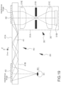
- the lower blade 73 is moved downward, and the upper blade 74 is moved upward (refer to FIG. 18 A ). Further, the fixation base 72 is moved upward (refer to FIG. 18 B ). Accordingly, the light guiding plate 41 (the resin plate 41 ′) having a desired outer shape and including the protrusion (specifically, a protrusion in the form of a burr) 51 extending from a portion of the lateral surface of the light guiding plate 41 can be obtained.
- the thickness t 1 or the height H 1 of the protrusion 51 when a space between the lower blade 73 and the upper blade 74 , or movement speeds of these blades 73 and 74 are adjusted, this makes it possible to change the thickness t 1 or the height H 1 of the protrusion 51 . Further, the thickness t 1 and the height H 1 are also changed according to a change including a change over time in shapes of the lower blade 73 and the upper blade 74 .
- the first deflection mechanism 42 and the second deflection mechanism 43 are arranged on (specifically, bonded to) the surface of the light guiding plate 41 (specifically, the first surface 41 A of the light guiding plate 41 ). Further, light that enters the light guiding plate 41 is diffractively reflected off the first deflection mechanism 42 , and the light being totally reflected within the light guiding plate 41 to propagate through the light guiding plate 41 is diffractively reflected off the second deflection mechanism 43 .
- FIG. 20 A is a schematic cross-sectional view of an enlarged portion of a reflective volume-hologram diffraction grating member.
- An interference fringe that has an angle of inclination (a slant angle) ⁇ is formed in the reflective volume-hologram diffraction grating member.
- the angle of inclination ⁇ refers to an angle formed by an interference fringe and the surface of a reflective volume-hologram diffraction grating member.
- the interference fringe is formed from the interior of the reflective volume-hologram diffraction grating member to the surface of the reflective volume-hologram diffraction grating member.
- the interference fringe satisfies the Bragg condition.
- the Bragg condition refers to a condition that satisfies Formula (A) indicated below.
- the first diffraction grating member 42 is arranged on (bonded to) the first surface 41 A of the light guiding plate 41 , and parallel light that enters the light guiding plate 41 from the second surface 41 B is diffractively reflected off the first diffraction grating member 42 such that the parallel light entering the light guiding plate 41 is totally reflected within the light guiding plate 41 .
- the second diffraction grating member 43 is arranged on (bonded to) the first surface 41 A of the light guiding plate 41 , and the parallel light being totally reflected within the light guiding plate 41 to propagate through the light guiding plate 41 is diffractively reflected off the second diffraction grating member 43 , and exits the light guiding plate 41 from the second surface 41 B in the form of the parallel light.
- the number of reflections of parallel light that enters the light guiding plate 41 at an angle at which the parallel light enters in a direction of the second diffraction grating member 43 is smaller than the number of reflections of parallel light that enters the light guiding plate 41 at an angle at which the parallel light enters in a direction opposite to the second diffraction grating member 43 .
- the reason is that, when light that propagates through the light guiding plate 41 impinges on an inner face of the light guiding plate 41 , the light forms a smaller angle with a normal line of the light guiding plate 41 in the case of parallel light that is diffractively reflected off the first diffraction grating member 42 , and enters the light guiding plate 41 at an angle at which the parallel light enters in a direction of the second diffraction grating member 43 , compared to the case of parallel light that enters the light guiding plate 41 at an angle at which the parallel light enters in the opposite direction.
- the shape of an interference fringe formed in the second diffraction grating member 43 and the shape of an interference fringe formed in the first diffraction grating member 42 are symmetric about an imaginary plane that is vertical to the axis of the light guiding plate 41 .
- Surfaces of the first diffraction grating member 42 and the second diffraction grating member 43 that do not face the light guiding plate 41 may be covered with a transparent resin plate or a transparent resin film to prevent the first diffraction grating member 42 and the second diffraction grating member 43 from being damaged.
- a transparent protective film may be attached to the second surface 41 B to protect the light guiding plate 41 .
- the light guiding plate 41 in the fourth embodiment described later includes the same configuration and structure as those of the light guiding plate 41 described above.
- the image forming apparatus 30 is the image forming apparatus having the first configuration, and includes a plurality of pixels arranged in a two-dimensional matrix.
- the image forming apparatus 30 includes an organic EL display apparatus 31 B.
- An image that exits the organic EL display apparatus 31 B passes through a first convex lens 31 C that is included in a lens system.
- the image further passes through a second convex lens 31 E that is included in the lens system to become parallel light, and is headed for the light guiding plate 41 .
- a front focal position f 2 F of the second convex lens 31 E coincides with a back focal position f 1 B of the first convex lens 31 C.
- a diaphragm 31 D is arranged at the back focal position f 1 B of the first convex lens 31 C (the front focal position f 2 F of the second convex lens 31 E).
- the diaphragm 31 D corresponds to an image exit section.
- the entirety of the image forming apparatus 30 is accommodated in a housing 31 A (the housing 30 ′).
- the housing 31 A is attached to the frame 10 by an appropriate method.
- the organic EL display apparatus 31 B includes a plurality of (for example, 640 ⁇ 480) pixels (organic EL elements) arranged in a two-dimensional matrix.
- the image forming apparatus 30 is the image forming apparatus having the first configuration, and includes a plurality of pixels arranged in a two-dimensional matrix.
- the image forming apparatus 30 includes a reflective spatial light modulating apparatus, and a light source 32 B including a light-emitting diode that emits white light.
- the entirety of the image forming apparatus 30 is accommodated in a housing 32 A (indicated by a dot-dash line in FIG. 20 B ).
- the housing 32 A (the housing 30 ′) includes an opening (not illustrated), and light exits an optical system (a parallel-light output optical system or a collimating optical system 32 E) through the opening.
- the housing 32 A is attached to the frame 10 by an appropriate method.
- the reflective spatial light modulating apparatus includes a liquid crystal display apparatus (LCD) 32 D of LCOS that serves as a light bulb.
- the reflective spatial light modulating apparatus further includes a polarization beam splitter 32 C in which a portion of light from the light source 32 B is reflected off the polarization beam splitter 32 C to be guided to the liquid crystal display apparatus 32 D, and a portion of light reflected off the liquid crystal display apparatus 32 D passes through the polarization beam splitter 32 C to be guided to the optical system 32 E.
- the liquid crystal display apparatus 32 D includes a plurality of (for example, 640 ⁇ 480) pixels (liquid crystal cells or liquid crystal display elements) arranged in a two-dimensional matrix.
- the polarization beam splitter 32 C has a well-known configuration and structure.
- a p-polarization component passes through the polarization beam splitter 32 C, and exits the system.
- an s-polarization component is reflected off the polarization beam splitter 32 C, and enters the liquid crystal display apparatus 32 D. Further, the s-polarization component is reflected within the liquid crystal display apparatus 32 D, and exits the liquid crystal display apparatus 32 D.
- light exiting a pixel used to display “white” includes a large amount of p-polarization component
- light exiting a pixel used to display “black” includes a large amount of s-polarization component.
- the p-polarization component passes through the polarization beam splitter 32 C to be guided to the optical system 32 E.
- the s-polarization component is reflected off the polarization beam splitter 32 C to be returned to the light source 32 B.
- the optical system 32 E includes, for example, a convex lens, and the image forming apparatus 30 (more specifically, the liquid crystal display apparatus 32 D) is arranged at a point (a position) corresponding to a focal length of the optical system 32 E, in order to generate parallel light.
- An image exiting the image forming apparatus 30 reaches the pupil 61 of the observer 60 through the optical member 40 .
- Information and data regarding an image to be displayed on the image display apparatus 20 , or a signal to be received by a reception apparatus is recorded, held, or saved in, for example, a so-called cloud computer or server.
- the display apparatus includes a communication mechanism (a transmission-and-reception apparatus) such as a cellular phone or a smartphone, or when the communication mechanism (the reception apparatus) is incorporated into the control apparatus (the control circuit or the control mechanism) 18 included in the display apparatus, various information and data, or a signal can be communicated and exchanged between the cloud computer or server and the display apparatus through the communication mechanism; a signal based on various information and data, that is, a signal used to display an image on the image display apparatus 20 can be received; and the reception apparatus can receive a signal.
- a communication mechanism such as a cellular phone or a smartphone
- the control apparatus the control circuit or the control mechanism 18 included in the display apparatus
- various information and data, or a signal can be communicated and exchanged between the cloud computer or server and the display apparatus through the
- the control apparatus 18 receives a signal used to display an image on the image display apparatus 20 .
- the control apparatus 18 performs well-known image processing on the basis of the received signal, and displays the “information” on the image forming apparatus 30 in the form of an image.
- the image of the “information” is displayed at a specified position on the light guiding plate 41 in the form of a virtual image, on the basis of light exiting the image forming apparatus 30 , the specified position being controlled by the control apparatus 18 .
- a virtual image is formed in a portion of a virtual image forming region (the second deflection mechanism 43 ).
- an image captured by an image-capturing apparatus (a camera) 19 that is provided to a center portion 11 ′ of the rim portion 11 may be transmitted to a cloud computer or a server through the communication mechanism, various information and data that correspond to the image captured by the image-capturing apparatus 19 may be searched for in the cloud computer or the server, various information and data that are obtained by the search may be transmitted to the display apparatus through the communication mechanism, and an image may be displayed on the image display apparatus 20 on the basis of the various information and data being obtained by the search.
- information regarding, for example, the location of an observer and a direction that the observer is facing can be added. This makes it possible to display the “information” on the image forming apparatus 30 with a higher degree of accuracy.
- the light source 33 B includes, for example, a semiconductor laser element. Further, light emitted by the light source 33 B is formed into parallel light by a lens (not illustrated). The parallel light is horizontally scanned and vertically scanned by the scanning mechanism 33 C, which is a MEMS mirror that includes a two-dimensionally rotatable micromirror and can two-dimensionally scan incident parallel light. A kind of two-dimensional image is formed, and a virtual pixel (the number of pixels may be, for example, the same as the number of pixels in the third embodiment) is generated. Further, light from the virtual pixel (the scanning mechanism 33 C corresponding to an image exit portion) passes through the lens system 33 D having a positive optical power. A pencil of light is formed into parallel light, and the parallel light enters the light guiding plate 41 .
- the scanning mechanism 33 C which is a MEMS mirror that includes a two-dimensionally rotatable micromirror and can two-dimensionally scan incident parallel light. A kind of two-dimensional image is formed, and a virtual pixel
- FIG. 22 is a conceptual diagram of the image display apparatus 20 in the display apparatus (a head-mounted display) of the fifth embodiment.
- a first deflection mechanism 42 ′ and a second deflection mechanism 43 ′ are arranged within a light guiding plate 141 . Further, light that enters the light guiding plate 141 is reflected off the first deflection mechanism 42 ′, and the light being totally reflected within the light guiding plate 141 to propagate through the light guiding plate 141 is transmitted through and reflected off the second deflection mechanism 43 ′ multiple times.
- the first deflection mechanism 42 ′ serves as a reflecting mirror
- the second deflection mechanism 43 ′ serves as a semi-transmissive mirror.
- the first deflection mechanism 42 ′ provided within the light guiding plate 141 includes a light reflective film (a type of mirror) that is made of aluminum (Al) and off which light that enters the light guiding plate 141 is reflected.
- the second deflection mechanism 43 ′ provided within the light guiding plate 141 includes a multilayer stacking structure that includes multilayered dielectric film stacks.
- the dielectric film stack includes, for example, a TiO 2 film that is a high dielectric constant material, and a SiO 2 film that is a low dielectric constant material.
- Japanese Unexamined Patent Application Publication No. 2005-521099 discloses a multilayer stacking structure that includes multilayered dielectric film stacks.
- FIG. 24 A is a schematic cross-sectional view of the optical member of the sixth embodiment
- FIG. 24 B is a schematic plan view of, for example, a resin plate, the schematic plan view being used to describe a method for manufacturing the optical member of the sixth embodiment.
- the sixth embodiment is different from the first to fifth embodiments in that a first deflection mechanism 142 and a second deflection mechanism 143 each include a diffractive optical element (DOE). Further, the hard coat layer 47 is not formed.
- the first deflection mechanism 142 and the second deflection mechanism 143 are formed integrally with a resin plate 141 ′ using the same material as the resin plate 141 ′. Specifically, the first deflection mechanism 142 and the second deflection mechanism 143 are formed by polycarbonate-resin injection molding. Except for the points described above, the light guiding plate 141 of the sixth embodiment includes a configuration and a structure that are similar to those of the light guiding plate 41 of the first embodiment.
- first deflection mechanism 142 and the second deflection mechanism 143 are formed integrally with the resin plate 141 ′, a plurality of deflection mechanisms including the first deflection mechanism 142 and the second deflection mechanism 143 is positioned relative to the resin plate 141 ′ with a very high degree of accuracy.
- the convex portion provided to the on-placement base 71 is fitted into the center hole provided to the resin plate 141 ′, and the resin plate 141 ′ is rotatably fixed to the on-placement base 71 to perform alignment while rotating the resin plate 141 ′.
- the first deflection mechanism 142 and the second deflection mechanism 143 are formed integrally with the resin plate 141 ′ larger than the resin plate 141 ′ forming the light guiding plate 40 . Thereafter, alignment is performed on the basis of the first deflection mechanism 142 or the second deflection mechanism 143 , and an outer shape process that is specifically stamping is performed on the resin plate 141 ′ to manufacture a light guiding plate.
- the optical member manufacturing method of the sixth embodiment makes it possible to form the resin plate 141 ′ in size of a general-purpose CD by resin molding. This results in being able to use existing facilities, and thus in providing a great effect in reducing costs.
- stamping is adopted as the outer shape process in the optical member manufacturing method of the sixth embodiment described above, but cutting can also be adopted.
- the resin plate 141 ′ is manufactured by polycarbonate-resin injection molding.
- a polycarbonate resin is slightly less fluent than cycloolefin copolymer (COP) upon performing injection molding, but is generally used in a CD and a DVD. This results in being able to use existing facilities, and thus in providing a great effect in reducing costs.
- the resin plate exhibits excellent optical characteristics since proven formation conditions can be used.
- a light guiding plate that includes a protrusion extending from a portion of a lateral surface of the light guiding plate, and that includes a first deflection mechanism and a second deflection mechanism that each include a diffractive optical element (DOE) can also be obtained by injection molding.
- DOE diffractive optical element
- the present disclosure has been described above on the basis of the favorable embodiments. However, the present disclosure is not limited to these embodiments.
- the configurations and the structures of the display apparatus (the head-mounted display), the image display apparatus, and the optical member described in the embodiments are merely illustrative, and modifications may be made thereto as appropriate.
- a surface relief hologram (refer to US 2004/0062505 A1) may be provided to the light guiding plate, or the surface relief diffraction grating disclosed in U.S. Pat. No. 9,513,480 B2 (US 2016/0231568 A1) may be used as the diffraction grating member.
- One of the first deflection mechanism and the second deflection mechanism may include a reflective diffraction grating member, and the other may include a transmissive diffraction grating member.
- the diffraction grating member may be a reflective blazed diffraction grating member, or the hologram diffraction grating member may include the polymer-dispersed liquid crystal (PDLC) mixture disclosed in Japanese Patent Application Laid-open No. 2014-132328.
- PDLC polymer-dispersed liquid crystal
- the image forming apparatus displays an image in one color (for example, green) has been described in the embodiments, but the image forming apparatus can also display a color image.
- the light source includes a light source that emits red light, a light source that emits green light, and a light source that emits blue light. More specifically, it is sufficient if, for example, red light, green light, and blue light that are respectively emitted by a red-light-emitting element, a green-light-emitting element, and a blue-light-emitting element are mixed and the brightness is made uniform using a light pipe to obtain white light.
- FIGS. 25 and 26 illustrate modifications of the optical member illustrated in the third or fourth embodiment.
- a hologram lens 46 may be arranged on the optical member 40 to face the second deflection mechanism 43 .
- Light from the image forming apparatus 30 is deflected by (or reflected off) the first deflection mechanism 42 , and is totally reflected within the light guiding plate 41 to propagate through the light guiding plate 41 .
- the light is deflected by the second deflection mechanism 43 to enter the hologram lens 46 , and exits the hologram lens 46 to be headed for the pupil 61 of the observer 60 .
- a large portion of light passing through the second deflection mechanism 43 does not satisfy the diffraction condition for the second deflection mechanism 43 .
- FIG. 27 illustrates a conceptual diagram of the optical member, and as illustrated in FIG. 27 , a first reflective volume-hologram diffraction grating member 48 A, a second reflective volume-hologram diffraction grating member 48 B, and a third reflective volume-hologram diffraction grating member 48 C may be included.
- a first reflective volume-hologram diffraction grating member 48 A an interference fringe of a diffraction grating member extends substantially parallel to a Y axis (a y axis).
- a line that connects an entrance point and an exit point includes two lines L 0 -A and L 0 -B.
- a light-guiding region includes two regions that are
- the hologram diffraction grating member on the light entrance side may be the two reflective diffraction grating members 42 A and 42 B, and the hologram diffraction grating member on the light exit side may be the two reflective diffraction grating members 43 A and 43 B.
- the hologram diffraction grating member on the light entrance side may be a transmissive diffraction grating member 42 C, and the hologram diffraction grating member on the light exit side may be a transmissive diffraction grating member 43 C.
- a display apparatus including:
Landscapes
- Physics & Mathematics (AREA)
- General Physics & Mathematics (AREA)
- Optics & Photonics (AREA)
- Engineering & Computer Science (AREA)
- Health & Medical Sciences (AREA)
- Manufacturing & Machinery (AREA)
- Ophthalmology & Optometry (AREA)
- Mechanical Engineering (AREA)
- Multimedia (AREA)
- Signal Processing (AREA)
Abstract
Description
-
- Patent Literature 1: Japanese Patent Application Laid-open No. 2010-032997
- Patent Literature 2: Japanese Patent Application Laid-open No. 2013-109301
- Patent Literature 3: Japanese Patent Application Laid-open No. 2008-065262
-
- a frame that includes a rim portion; and
- an image display apparatus that is attached to the frame,
- the image display apparatus including
- an image forming apparatus, and
- an optical member that guides an image coming from the image forming apparatus to a pupil of an observer,
- the optical member including
- a light guiding plate that is formed of a resin plate, and includes a first surface and a second surface that faces the first surface,
- a first deflection mechanism that is provided to the first surface or the second surface of the light guiding plate, and
- a second deflection mechanism that is provided to the first surface or the second surface of the light guiding plate, in which
- light that enters the light guiding plate from the image forming apparatus through the first surface or the second surface is deflected by the first deflection mechanism, is totally reflected within the light guiding plate to propagate through the light guiding plate, is then deflected by the second deflection mechanism, and exits the light guiding plate through the second surface to be headed for the observer,
- the light guiding plate includes a protrusion that extends from a portion of a lateral surface of the light guiding plate, and
- the light guiding plate is fixed to an interior lateral face of the rim portion using an adhesive in a state in which a tip of the protrusion is in contact with the interior lateral face of the rim portion. Note that the term “total reflection” refers to an internal total reflection or a total reflection within the light guiding plate. The light entering from the image forming apparatus is totally reflected within the light guiding plate to propagate through the light guiding plate, and then the light exits the light guiding plate to be headed for the observer. The second deflection mechanism includes a virtual image forming region of the optical member.
-
- a light guiding plate that is formed of a resin plate, and includes a first surface and a second surface that faces the first surface;
- a first deflection mechanism that is provided to the first surface or the second surface of the light guiding plate; and
- a second deflection mechanism that is provided to the first surface or the second surface of the light guiding plate, in which
- light that enters the light guiding plate from the image forming apparatus through the first surface or the second surface is deflected by the first deflection mechanism, is totally reflected within the light guiding plate to propagate through the light guiding plate, is then deflected by the second deflection mechanism, and exits the light guiding plate through the second surface to be headed for the observer, and
- the light guiding plate includes a protrusion that extends from a portion of a lateral surface of the light guiding plate.
-
- a light guiding plate that is formed of a resin plate, and includes a first surface and a second surface that faces the first surface,
- a first deflection mechanism that is provided to the first surface or the second surface of the light guiding plate, and
- a second deflection mechanism that is provided to the first surface or the second surface of the light guiding plate, in which
- light that enters the light guiding plate from the image forming apparatus through the first surface or the second surface is deflected by the first deflection mechanism, is totally reflected within the light guiding plate to propagate through the light guiding plate, is then deflected by the second deflection mechanism, and exits the light guiding plate through the second surface to be headed for the observer, and
- the light guiding plate includes a protrusion that extends from a portion of a lateral surface of the light guiding plate, the stamping apparatus including:
- an on-placement base on which the resin plate provided with the first deflection mechanism and the second deflection mechanism is placed;
- a fixation base that fixes, to the on-placement base, the resin plate provided with the first deflection mechanism and the second deflection mechanism;
- a lower blade used to perform stamping on the resin plate; and
- an upper blade used to perform stamping on the resin plate.
-
- a light guiding plate that is formed of a resin plate, and includes a first surface and a second surface that faces the first surface,
- a first deflection mechanism that is provided to the first surface or the second surface of the light guiding plate, and
- a second deflection mechanism that is provided to the first surface or the second surface of the light guiding plate, in which
- light that enters the light guiding plate from the image forming apparatus through the first surface or the second surface is deflected by the first deflection mechanism, is totally reflected within the light guiding plate to propagate through the light guiding plate, is then deflected by the second deflection mechanism, and exits the light guiding plate through the second surface to be headed for the observer, the method including:
- providing the resin plate provided with the first deflection mechanism and the second deflection mechanism; and
- performing an outer shape process on the resin plate to obtain the light guiding plate having a desired outer shape and including a protrusion that extends from a portion of a lateral surface of the light guiding plate.
-
- 1. General Descriptions of Display Apparatus of Present Disclosure, Optical Member of Present Disclosure, Method for Manufacturing Optical Member, and Stamping Apparatus of Present Disclosure
- 2. First Embodiment (Display Apparatus of Present Disclosure and Optical Member of Present Disclosure)
- 3. Second Embodiment (Method for Manufacturing Optical Member and Stamping Apparatus of Present Disclosure)
- 4. Third Embodiment (Modification of First and Second Embodiments, Image Forming Apparatus Having First Configuration)
- 5. Fourth Embodiment (Modification of First and Second Embodiments, Image Forming Apparatus Having Second Configuration)
- 6. Fifth Embodiment (Modification of Third and Fourth Embodiments)
- 7. Fifth Embodiment (Modification of Display Apparatus of First Embodiment and Method for Manufacturing Display Apparatus)
- 8. Others
-
- an alignment reference point that is provided to an on-placement base, and
- an alignment mechanism that aligns the first deflection mechanism or the second deflection mechanism with the alignment reference point to control a relationship in relative position between the on-placement base and a direction horizontal to a lower blade and an upper blade. Further, in the stamping apparatus of the present disclosure including such a favorable configuration, a specified space may be formed between the lower blade and the upper blade upon performing stamping on a resin plate. Note that, when there is a need to provide a protrusion to a specific region in the light guiding plate, it is sufficient if a space between the lower blade and the upper blade that corresponds to the specific region is made larger than a space between the lower blade and the upper blade in a region other than the specific region. Further, in the stamping apparatus of the present disclosure including the various favorable configurations, a concave portion may be formed in a portion, in the on-placement base or a fixation base, that faces the deflection mechanism, and the deflection mechanism and the on-placement base or the fixation base may be out of contact with each other.
-
- a
frame 10 that includes a rim portion (a front portion) 11, and - an
image display apparatus 20 that is attached to theframe 10, - the
image display apparatus 20 including- an
image forming apparatus 30, and - an
optical member 40 that guides an image coming from theimage forming apparatus 30 to a pupil of an observer,
- an
- the
optical member 40 including- a
light guiding plate 41 that is formed of aresin plate 41′, and includes afirst surface 41A and asecond surface 41B that faces thefirst surface 41A, - a
first deflection mechanism 42 that is provided to thefirst surface 41A or thesecond surface 41B (specifically, thefirst surface 41A in the first embodiment) of thelight guiding plate 41, and - a
second deflection mechanism 43 that is provided to thefirst surface 41A or thesecond surface 41B (specifically, thefirst surface 41A in the first embodiment) of thelight guiding plate 41, in which
- a
- light that enters the
light guiding plate 41 from theimage forming apparatus 30 through thefirst surface 41A or thesecond surface 41B (specifically, thesecond surface 41B in the first embodiment) is deflected by thefirst deflection mechanism 42, is totally reflected within thelight guiding plate 41 to propagate through thelight guiding plate 41, is then deflected by thesecond deflection mechanism 43, and exits thelight guiding plate 41 through thesecond surface 41B to be headed for theobserver 60.
- a
-
- the
light guiding plate 41 is fixed to an interiorlateral face 11A of therim portion 11 using an adhesive 52 in a state in which a tip 51A of theprotrusion 51 is in contact with the interiorlateral face 11A of therim portion 11. Note that, with respect to a region indicated by an arrow “X” inFIG. 1A , an illustration of the adhesive 52 is omitted in order to clearly depict the state in which the tip 51A of theprotrusion 51 is in contact with the interiorlateral face 11A of therim portion 11.
- the
-
- the
light guiding plate 41 formed of theresin plate 41′, thelight guiding plate 41 including thefirst surface 41A, and thesecond surface 41B facing thefirst surface 41A, - the
first deflection mechanism 42 provided to thefirst surface 41A or thesecond surface 41B (specifically, thefirst surface 41A in the first embodiment) of thelight guiding plate 41, and - the
second deflection mechanism 43 provided to thefirst surface 41A or thesecond surface 41B (specifically, thefirst surface 41A in the first embodiment) of thelight guiding plate 41, in which - light that enters the
light guiding plate 41 from theimage forming apparatus 30 through thefirst surface 41A or thesecond surface 41B (specifically, thesecond surface 41B in the first embodiment) is deflected by thefirst deflection mechanism 42, is totally reflected within thelight guiding plate 41 to propagate through thelight guiding plate 41, is then deflected by thesecond deflection mechanism 43, and exits thelight guiding plate 41 through thesecond surface 41B to be headed for the observer, and - the
light guiding plate 41 includes the protrusion (specifically, a protrusion in the form of a burr) 51 extending from the portion of the lateral surface of thelight guiding plate 41.
- the
-
- an on-placement base (an on-placement stage) 71 on which the
resin plate 41′ provided with thefirst deflection mechanism 42 and thesecond deflection mechanism 43 is placed, - a fixation base (a fixation stage) 72 that fixes, to the on-placement base, the
resin plate 41′ provided with thefirst deflection mechanism 42 and thesecond deflection mechanism 43, - a
lower blade 73 used to perform stamping on theresin plate 41′, and - an
upper blade 74 used to perform stamping on theresin plate 41′.
- an on-placement base (an on-placement stage) 71 on which the
-
- an
alignment reference point 75 that is provided to the on-placement base 71, and - an alignment mechanism that aligns the
first deflection mechanism 42 or thesecond deflection mechanism 43 with thealignment reference point 75 to control a relationship in relative position between the on-placement base 71 and a direction horizontal to the lower blade and the upper blade. Further, a specified space may be formed between thelower blade 73 and theupper blade 74 upon performing stamping on theresin plate 41′. Note that, when there is a need to provide a protrusion (specifically, a protrusion in the form of a burr) to a specific region in thelight guiding plate 41, a space between thelower blade 73 and theupper blade 74 that corresponds to the specific region may be made larger than a space between thelower blade 73 and theupper blade 74 in a region other than the specific region. Further, aconcave portion 76 is formed in a portion, in the on-placement base 71 or the fixation base 72 (specifically, thefixation base 72 in the second embodiment), that faces thedeflection mechanism deflection mechanism placement base 71 or the fixation base 72 (specifically, thefixation base 72 in the second embodiment) are out of contact with each other.
- an
m·λ=2·d·sin(Θ) (A)
Θ=90°−(φ+ψ) (B)
-
- [A] a region, in the
light guiding plate 41, that faces a region situated between a right end of the first reflective volume-hologramdiffraction grating member 48A inFIG. 27 and a left end of the third reflective volume-hologram diffraction grating member 48C inFIG. 27 , and - [B] a region, in the
light guiding plate 41, that faces a region situated between a lower end of the third reflective volume-hologram diffraction grating member 48C inFIG. 27 and an upper end of the second reflective volume-hologramdiffraction grating member 48B inFIG. 27 .
- [A] a region, in the
-
- the two regions in the
light guiding plate 41 described above, - [C] a region, in the
light guiding plate 41, that faces the first reflective volume-hologramdiffraction grating member 48A, - [D] a region, in the
light guiding plate 41, that faces the third reflective volume-hologram diffraction grating member 48C, and - [E] a region, in the
light guiding plate 41, that faces the second reflective volume-hologramdiffraction grating member 48B.
- the two regions in the
-
- a frame that includes a rim portion; and
- an image display apparatus that is attached to the frame,
- the image display apparatus including
- an image forming apparatus, and
- an optical member that guides an image coming from the image forming apparatus to a pupil of an observer,
- the optical member including
- a light guiding plate that is formed of a resin plate, and includes a first surface and a second surface that faces the first surface,
- a first deflection mechanism that is provided to the first surface or the second surface of the light guiding plate, and
- a second deflection mechanism that is provided to the first surface or the second surface of the light guiding plate, in which
- light that enters the light guiding plate from the image forming apparatus through the first surface or the second surface is deflected by the first deflection mechanism, is totally reflected within the light guiding plate to propagate through the light guiding plate, is then deflected by the second deflection mechanism, and exits the light guiding plate through the second surface to be headed for the observer,
- the light guiding plate includes a protrusion (specifically, a protrusion in the form of a burr) that extends from a portion of a lateral surface of the light guiding plate, and
- the light guiding plate is fixed to an interior lateral face of the rim portion using an adhesive in a state in which a tip of the protrusion is in contact with the interior lateral face of the rim portion.
- [A02] The display apparatus according to [A01], in which
- t1/t0≤0.05, and favorably, 0.01≤t1/t0≤0.05 is satisfied when a thickness of the light guiding plate is t0 and a thickness of the protrusion is t1.
- [A03] The display apparatus according to [A01] or [A02], in which
- 0.05≤H1/t0≤0.2 is satisfied when a thickness of the light guiding plate is t0 and a height of the protrusion that is measured from the lateral surface of the light guiding plate is H1.
- [A04] The display apparatus according to any one of [A01] to [A03], in which
- a light-guiding-plate receiving portion is provided to the rim portion to face an outer peripheral portion of the light guiding plate.
- [A05] The display apparatus according to [A04], in which
- the light-guiding-plate receiving portion is provided to the rim portion to face a portion of the outer peripheral portion of the light guiding plate.
- [A06] The display apparatus according to any one of [A01] to [A05], in which
- all of the periphery of the light guiding plate is fixed to the interior lateral face of the rim portion using the adhesive.
- [A07] The display apparatus according to any one of [A01] to [A05], in which
- a portion of the light guiding plate is fixed to the interior lateral face of the rim portion using the adhesive.
- [A08] The display apparatus according to any one of [A01] to [A07], in which the adhesive is an ultraviolet curable adhesive.
- [A09] The display apparatus according to any one of [A01] to [A08], in which
- the light guiding plate is formed of a transparent resin plate.
- [A10] The display apparatus according to any one of [A01] to [A09], in which
- a hard coat layer is formed on the first surface and the second surface of the light guiding plate.
- [A11] The optical member according to [A10], in which
- the hard coat layer is not formed on the lateral surface of the light guiding plate.
- [A12] The optical member according to [A10] or [A11], in which
- the hard coat layer is made of an organic material of which a contact angle with respect to water is greater than or equal to 100 degrees and of which a pencil hardness is greater than or equal to 4H.
[B01] «Optical Member»
- the hard coat layer is made of an organic material of which a contact angle with respect to water is greater than or equal to 100 degrees and of which a pencil hardness is greater than or equal to 4H.
-
- a light guiding plate that is formed of a resin plate, and includes a first surface and a second surface that faces the first surface;
- a first deflection mechanism that is provided to the first surface or the second surface of the light guiding plate; and
- a second deflection mechanism that is provided to the first surface or the second surface of the light guiding plate, in which
- light that enters the light guiding plate from the image forming apparatus through the first surface or the second surface is deflected by the first deflection mechanism, is totally reflected within the light guiding plate to propagate through the light guiding plate, is then deflected by the second deflection mechanism, and exits the light guiding plate through the second surface to be headed for the observer, and
- the light guiding plate includes a protrusion (specifically, a protrusion in the form of a burr) that extends from a portion of a lateral surface of the light guiding plate.
[C01] «Method for Manufacturing Optical Member»
-
- a light guiding plate that is formed of a resin plate, and includes a first surface and a second surface that faces the first surface,
- a first deflection mechanism that is provided to the first surface or the second surface of the light guiding plate, and
- a second deflection mechanism that is provided to the first surface or the second surface of the light guiding plate, in which
- light that enters the light guiding plate from the image forming apparatus through the first surface or the second surface is deflected by the first deflection mechanism, is totally reflected within the light guiding plate to propagate through the light guiding plate, is then deflected by the second deflection mechanism, and exits the light guiding plate through the second surface to be headed for the observer, the method including:
- providing the resin plate provided with the first deflection mechanism and the second deflection mechanism; and
- performing an outer shape process on the resin plate to obtain the light guiding plate having a desired outer shape and including a protrusion (specifically, a protrusion in the form of a burr) that extends from a portion of a lateral surface of the light guiding plate.
- [C02] The method for manufacturing an optical member according to [C01], in which
- the outer shape process is stamping.
- [C03] The method for manufacturing an optical member according to [C01] or [C02], in which
- the first deflection mechanism and the second deflection mechanism are formed integrally with the resin plate.
- [C04] The method for manufacturing an optical member according to any one of [C01] to [C03], in which
- the resin plate is formed using a polycarbonate resin.
- [C05] The method for manufacturing an optical member according to any one of [C01] to [C04], in which
- the first deflection mechanism and the second deflection mechanism each include a diffractive optical element (DOE).
- [C06] The method for manufacturing an optical member according to any one of [C01] to [C05], in which
- before the outer shape process, the resin plate has a doughnut-like outer shape.
- [C07] The method for manufacturing an optical member according to any one of [C01] to [C05], in which
- before the outer shape process, the resin plate has an outer shape that is the same shape as a compact disc (CD).
- [C08] The method for manufacturing an optical member according to [C06] or [C07], in which
- a hole is provided to the center of the resin plate,
- before the outer shape process, a convex portion that is to be fitted into the hole is provided to an on-placement base on which the resin plate is placed, and
- the resin plate is rotatably fixed to the on-placement base.
[D01] «Stamping Apparatus»
-
- a light guiding plate that is formed of a resin plate, and includes a first surface and a second surface that faces the first surface,
- a first deflection mechanism that is provided to the first surface or the second surface of the light guiding plate, and
- a second deflection mechanism that is provided to the first surface or the second surface of the light guiding plate, in which
- light that enters the light guiding plate from the image forming apparatus through the first surface or the second surface is deflected by the first deflection mechanism, is totally reflected within the light guiding plate to propagate through the light guiding plate, is then deflected by the second deflection mechanism, and exits the light guiding plate through the second surface to be headed for the observer, and
- the light guiding plate includes a protrusion (specifically, a protrusion in the form of a burr) that extends from a portion of a lateral surface of the light guiding plate, the stamping apparatus including:
- an on-placement base on which the resin plate provided with the first deflection mechanism and the second deflection mechanism is placed;
- a fixation base that fixes, to the on-placement base, the resin plate provided with the first deflection mechanism and the second deflection mechanism;
- a lower blade used to perform stamping on the resin plate; and
- an upper blade used to perform stamping on the resin plate.
- [D02] The stamping apparatus according to [D01], further including:
- an alignment reference point that is provided to the on-placement base; and
- an alignment mechanism that aligns the first deflection mechanism or the second deflection mechanism with the alignment reference point to control a relationship in relative position between the on-placement base and a direction horizontal to the lower blade and the upper blade.
- [D03] The stamping apparatus according to [D01] or [D02], in which
- a specified space is formed between the lower blade and the upper blade upon performing stamping on the resin plate.
- [D04] The stamping apparatus according to any one of [D01] to [D03], in which
- a concave portion is formed in a portion, in the on-placement base or the fixation base, that faces the deflection mechanism, and
- the deflection mechanism and the on-placement base or the fixation base are out of contact with each other.
-
- 10 frame
- 11 rim portion (front portion)
- 11′ center portion of rim portion
- 11A interior lateral face of rim portion
- 11B edge of rim portion
- 11C projecting portion that projects from rim portion
- 12 temple portion
- 13 hinge
- 14 temple-tip covering portion (celluloid tip, ear-fit portion, ear pad)
- 15 wiring (such as signal line and power supply line)
- 16 headphone portion
- 16′ headphone-portion wiring
- 17 pad portion (nose pad portion)
- 18 control apparatus (control circuit, control mechanism)
- 19 image-capturing apparatus (camera)
- 20 image display apparatus
- 30 image forming apparatus
- 30′ housing
- 30″ attachment member
- 31A housing
- 31B organic EL display apparatus
- 31C first convex lens
- 31D diaphragm
- 31E second convex lens
- 32A housing
- 32B light source
- 32C polarization beam splitter
- 32D liquid crystal display apparatus (LCD)
- 32E optical system (parallel-light output optical system, collimating optical system)
- 33A housing
- 33B light source
- 33C scanning mechanism
- 33D lens system
- 40 optical member
- 41, 141 light guiding plate
- 41A first surface of light guiding plate
- 41B second surface of light guiding plate
- 41′ resin plate
- 42, 42′, 42A, 42B, 42C first deflection mechanism (first diffraction grating member)
- 43, 43′, 43A, 43B, 43C second deflection mechanism (second diffraction grating member)
- 44 portion, in light guiding plate, to which first deflection mechanism is provided
- 45 portion, in light guiding plate, to which second deflection mechanism is provided
- 46 hologram lens
- 47 hard coat layer
- 48A first reflective volume-hologram diffraction grating member
- 48B second reflective volume-hologram diffraction grating member
- 48C third reflective volume-hologram diffraction grating member
- 51 protrusion (protrusion in form of burr)
- 52 adhesive
- 53 light-guiding-plate receiving portion
- 60 observer
- 61 eyeball (pupil)
- 71 on-placement base
- 72 lower blade
- 73 fixation base
- 74 upper blade
- 75 alignment reference point
- 76 concave portion
Claims (18)
Applications Claiming Priority (3)
| Application Number | Priority Date | Filing Date | Title |
|---|---|---|---|
| JP2020-100738 | 2020-06-10 | ||
| JP2020100738 | 2020-06-10 | ||
| PCT/JP2021/020989 WO2021251237A1 (en) | 2020-06-10 | 2021-06-02 | Display device, optical member and method for manufacturing same, and punching device |
Publications (2)
| Publication Number | Publication Date |
|---|---|
| US20230204960A1 US20230204960A1 (en) | 2023-06-29 |
| US12276793B2 true US12276793B2 (en) | 2025-04-15 |
Family
ID=78846134
Family Applications (1)
| Application Number | Title | Priority Date | Filing Date |
|---|---|---|---|
| US17/928,489 Active 2041-12-17 US12276793B2 (en) | 2020-06-10 | 2021-06-02 | Display apparatus, optical member, method for manufacturing optical member, and stamping apparatus |
Country Status (2)
| Country | Link |
|---|---|
| US (1) | US12276793B2 (en) |
| WO (1) | WO2021251237A1 (en) |
Citations (19)
| Publication number | Priority date | Publication date | Assignee | Title |
|---|---|---|---|---|
| US20020060758A1 (en) * | 2000-11-22 | 2002-05-23 | Seung-Chul Jeong | Light guide device, and liquid crystal display module and liquid crystal display device having the same |
| JP2002540949A (en) | 1999-04-07 | 2002-12-03 | スリーエム イノベイティブ プロパティズ カンパニー | Method and apparatus for stamping parts from a multilayer strip |
| JP2005521099A (en) | 2002-03-21 | 2005-07-14 | ラマス リミテッド | Light guide optical device |
| JP2008065262A (en) | 2006-09-11 | 2008-03-21 | Hoya Corp | Spectacle lens, spectacle lenses working device, and working method of spectacle lens |
| US20080278661A1 (en) * | 2006-01-24 | 2008-11-13 | Myong Rock Oh | Backlight Unit and Lcd Having the Same |
| JP2010032997A (en) | 2008-06-30 | 2010-02-12 | Hoya Corp | Image display, and head mount display |
| US20100066938A1 (en) * | 2007-05-23 | 2010-03-18 | Jung Mok Lee | Display device |
| JP3166052U (en) | 2010-10-11 | 2011-02-17 | コリア オージーケー シーオー., エルティーディーKorea Ogk Co., Ltd | Easy-to-assemble glasses frame removable 3D glasses |
| US20130027634A1 (en) * | 2011-07-28 | 2013-01-31 | Ryuji Saneto | Liquid crystal display device |
| JP2013109301A (en) | 2011-11-24 | 2013-06-06 | Seiko Epson Corp | Half mirror and image display device |
| JP2013152407A (en) | 2012-01-26 | 2013-08-08 | Nikon Vision Co Ltd | Loupe |
| US20130308074A1 (en) * | 2012-05-17 | 2013-11-21 | Lg Display Co., Ltd. | Backlight unit and liquid crystal display device including the same |
| JP2014132328A (en) | 2012-11-16 | 2014-07-17 | Rockwell Collins Inc | Transparent waveguide display |
| US20140232619A1 (en) * | 2013-02-19 | 2014-08-21 | Seiko Epson Corporation | Virtual image display device |
| US20150277125A1 (en) * | 2014-03-25 | 2015-10-01 | Sony Corporation | Light guide unit, image display device, and display apparatus |
| US20170168228A1 (en) * | 2015-09-09 | 2017-06-15 | Shenzhen China Star Optoelectronics Technology Co. Ltd. | Backlight module and display device |
| WO2018135193A1 (en) | 2017-01-20 | 2018-07-26 | ソニー株式会社 | Optical device and display device |
| US20190011779A1 (en) * | 2017-07-07 | 2019-01-10 | Samsung Display Co., Ltd. | Optical member, display device including the same, and method of manufacturing the optical member |
| US20240142694A1 (en) * | 2023-02-08 | 2024-05-02 | Meta Platforms Technologies, Llc | 3d print microstructures for ar waveguide packaging and protection |
-
2021
- 2021-06-02 US US17/928,489 patent/US12276793B2/en active Active
- 2021-06-02 WO PCT/JP2021/020989 patent/WO2021251237A1/en not_active Ceased
Patent Citations (23)
| Publication number | Priority date | Publication date | Assignee | Title |
|---|---|---|---|---|
| JP2002540949A (en) | 1999-04-07 | 2002-12-03 | スリーエム イノベイティブ プロパティズ カンパニー | Method and apparatus for stamping parts from a multilayer strip |
| US20020060758A1 (en) * | 2000-11-22 | 2002-05-23 | Seung-Chul Jeong | Light guide device, and liquid crystal display module and liquid crystal display device having the same |
| JP2005521099A (en) | 2002-03-21 | 2005-07-14 | ラマス リミテッド | Light guide optical device |
| US20080278661A1 (en) * | 2006-01-24 | 2008-11-13 | Myong Rock Oh | Backlight Unit and Lcd Having the Same |
| JP2008065262A (en) | 2006-09-11 | 2008-03-21 | Hoya Corp | Spectacle lens, spectacle lenses working device, and working method of spectacle lens |
| US20100066938A1 (en) * | 2007-05-23 | 2010-03-18 | Jung Mok Lee | Display device |
| JP2010032997A (en) | 2008-06-30 | 2010-02-12 | Hoya Corp | Image display, and head mount display |
| JP3166052U (en) | 2010-10-11 | 2011-02-17 | コリア オージーケー シーオー., エルティーディーKorea Ogk Co., Ltd | Easy-to-assemble glasses frame removable 3D glasses |
| US8029132B1 (en) * | 2010-10-11 | 2011-10-04 | Korea Ogk Co., Ltd. | 3D eyeglasses with detachable front eyeglasses frame |
| US20130027634A1 (en) * | 2011-07-28 | 2013-01-31 | Ryuji Saneto | Liquid crystal display device |
| JP2013109301A (en) | 2011-11-24 | 2013-06-06 | Seiko Epson Corp | Half mirror and image display device |
| JP2013152407A (en) | 2012-01-26 | 2013-08-08 | Nikon Vision Co Ltd | Loupe |
| US20130308074A1 (en) * | 2012-05-17 | 2013-11-21 | Lg Display Co., Ltd. | Backlight unit and liquid crystal display device including the same |
| JP2014132328A (en) | 2012-11-16 | 2014-07-17 | Rockwell Collins Inc | Transparent waveguide display |
| US20140232619A1 (en) * | 2013-02-19 | 2014-08-21 | Seiko Epson Corporation | Virtual image display device |
| JP2014160112A (en) | 2013-02-19 | 2014-09-04 | Seiko Epson Corp | Virtual image display device |
| US20150277125A1 (en) * | 2014-03-25 | 2015-10-01 | Sony Corporation | Light guide unit, image display device, and display apparatus |
| JP2015184561A (en) | 2014-03-25 | 2015-10-22 | ソニー株式会社 | Light guide device, image display device, and display device |
| US20170168228A1 (en) * | 2015-09-09 | 2017-06-15 | Shenzhen China Star Optoelectronics Technology Co. Ltd. | Backlight module and display device |
| WO2018135193A1 (en) | 2017-01-20 | 2018-07-26 | ソニー株式会社 | Optical device and display device |
| US20190331921A1 (en) * | 2017-01-20 | 2019-10-31 | Sony Corporation | Optical device and display device |
| US20190011779A1 (en) * | 2017-07-07 | 2019-01-10 | Samsung Display Co., Ltd. | Optical member, display device including the same, and method of manufacturing the optical member |
| US20240142694A1 (en) * | 2023-02-08 | 2024-05-02 | Meta Platforms Technologies, Llc | 3d print microstructures for ar waveguide packaging and protection |
Non-Patent Citations (1)
| Title |
|---|
| International Search Report and Written Opinion of PCT Application No. PCT/JP2021/020989, issued on Aug. 31, 2021, 10 pages of ISRWO. |
Also Published As
| Publication number | Publication date |
|---|---|
| US20230204960A1 (en) | 2023-06-29 |
| WO2021251237A1 (en) | 2021-12-16 |
Similar Documents
| Publication | Publication Date | Title |
|---|---|---|
| US11016306B2 (en) | Optical device and method for producing the same, and display device | |
| US10477174B2 (en) | Image display device and display apparatus | |
| JP5678709B2 (en) | Display device | |
| JP6201836B2 (en) | Optical device and method for assembling the same, hologram diffraction grating, display device and alignment device | |
| JP5316391B2 (en) | Image display device and head-mounted display | |
| US9335549B2 (en) | Imaging lightguide with holographic boundaries | |
| US11003212B2 (en) | Image display device, display device, and adjustment method for display device | |
| JP7207406B2 (en) | Display device | |
| WO2018135193A1 (en) | Optical device and display device | |
| WO2016084831A1 (en) | Optical device and display device | |
| WO2017213907A1 (en) | Wrapped waveguide with large field of view | |
| US20180373038A1 (en) | Optics of wearable display devices | |
| JP6551476B2 (en) | Optical device and display device | |
| US20100302644A1 (en) | Slanted optical device | |
| US12276793B2 (en) | Display apparatus, optical member, method for manufacturing optical member, and stamping apparatus | |
| WO2017033601A1 (en) | Display device and display device adjustment method | |
| US20220214550A1 (en) | Image display apparatus and display apparatus | |
| EP4224241A1 (en) | Display device |
Legal Events
| Date | Code | Title | Description |
|---|---|---|---|
| FEPP | Fee payment procedure |
Free format text: ENTITY STATUS SET TO UNDISCOUNTED (ORIGINAL EVENT CODE: BIG.); ENTITY STATUS OF PATENT OWNER: LARGE ENTITY |
|
| AS | Assignment |
Owner name: SONY GROUP CORPORATION, JAPAN Free format text: ASSIGNMENT OF ASSIGNORS INTEREST;ASSIGNORS:SUZUKI, NOBUHIRO;MACHIDA, AKIO;YOSHIDA, TAKUJI;SIGNING DATES FROM 20221116 TO 20221205;REEL/FRAME:062268/0531 |
|
| STPP | Information on status: patent application and granting procedure in general |
Free format text: DOCKETED NEW CASE - READY FOR EXAMINATION |
|
| STPP | Information on status: patent application and granting procedure in general |
Free format text: NON FINAL ACTION MAILED |
|
| STPP | Information on status: patent application and granting procedure in general |
Free format text: RESPONSE TO NON-FINAL OFFICE ACTION ENTERED AND FORWARDED TO EXAMINER |
|
| STPP | Information on status: patent application and granting procedure in general |
Free format text: AWAITING TC RESP., ISSUE FEE NOT PAID |
|
| STPP | Information on status: patent application and granting procedure in general |
Free format text: NOTICE OF ALLOWANCE MAILED -- APPLICATION RECEIVED IN OFFICE OF PUBLICATIONS |
|
| STCF | Information on status: patent grant |
Free format text: PATENTED CASE |