US12276410B2 - LED light with replaceable module and intelligent connectivity - Google Patents
LED light with replaceable module and intelligent connectivity Download PDFInfo
- Publication number
- US12276410B2 US12276410B2 US16/953,259 US202016953259A US12276410B2 US 12276410 B2 US12276410 B2 US 12276410B2 US 202016953259 A US202016953259 A US 202016953259A US 12276410 B2 US12276410 B2 US 12276410B2
- Authority
- US
- United States
- Prior art keywords
- connector
- connector piece
- accessory
- voice
- communication
- Prior art date
- Legal status (The legal status is an assumption and is not a legal conclusion. Google has not performed a legal analysis and makes no representation as to the accuracy of the status listed.)
- Active
Links
Images


Classifications
-
- F—MECHANICAL ENGINEERING; LIGHTING; HEATING; WEAPONS; BLASTING
- F21—LIGHTING
- F21K—NON-ELECTRIC LIGHT SOURCES USING LUMINESCENCE; LIGHT SOURCES USING ELECTROCHEMILUMINESCENCE; LIGHT SOURCES USING CHARGES OF COMBUSTIBLE MATERIAL; LIGHT SOURCES USING SEMICONDUCTOR DEVICES AS LIGHT-GENERATING ELEMENTS; LIGHT SOURCES NOT OTHERWISE PROVIDED FOR
- F21K9/00—Light sources using semiconductor devices as light-generating elements, e.g. using light-emitting diodes [LED] or lasers
- F21K9/20—Light sources comprising attachment means
- F21K9/23—Retrofit light sources for lighting devices with a single fitting for each light source, e.g. for substitution of incandescent lamps with bayonet or threaded fittings
- F21K9/232—Retrofit light sources for lighting devices with a single fitting for each light source, e.g. for substitution of incandescent lamps with bayonet or threaded fittings specially adapted for generating an essentially omnidirectional light distribution, e.g. with a glass bulb
-
- F—MECHANICAL ENGINEERING; LIGHTING; HEATING; WEAPONS; BLASTING
- F21—LIGHTING
- F21K—NON-ELECTRIC LIGHT SOURCES USING LUMINESCENCE; LIGHT SOURCES USING ELECTROCHEMILUMINESCENCE; LIGHT SOURCES USING CHARGES OF COMBUSTIBLE MATERIAL; LIGHT SOURCES USING SEMICONDUCTOR DEVICES AS LIGHT-GENERATING ELEMENTS; LIGHT SOURCES NOT OTHERWISE PROVIDED FOR
- F21K9/00—Light sources using semiconductor devices as light-generating elements, e.g. using light-emitting diodes [LED] or lasers
- F21K9/20—Light sources comprising attachment means
- F21K9/23—Retrofit light sources for lighting devices with a single fitting for each light source, e.g. for substitution of incandescent lamps with bayonet or threaded fittings
- F21K9/237—Details of housings or cases, i.e. the parts between the light-generating element and the bases; Arrangement of components within housings or cases
-
- F—MECHANICAL ENGINEERING; LIGHTING; HEATING; WEAPONS; BLASTING
- F21—LIGHTING
- F21K—NON-ELECTRIC LIGHT SOURCES USING LUMINESCENCE; LIGHT SOURCES USING ELECTROCHEMILUMINESCENCE; LIGHT SOURCES USING CHARGES OF COMBUSTIBLE MATERIAL; LIGHT SOURCES USING SEMICONDUCTOR DEVICES AS LIGHT-GENERATING ELEMENTS; LIGHT SOURCES NOT OTHERWISE PROVIDED FOR
- F21K9/00—Light sources using semiconductor devices as light-generating elements, e.g. using light-emitting diodes [LED] or lasers
- F21K9/20—Light sources comprising attachment means
- F21K9/23—Retrofit light sources for lighting devices with a single fitting for each light source, e.g. for substitution of incandescent lamps with bayonet or threaded fittings
- F21K9/238—Arrangement or mounting of circuit elements integrated in the light source
-
- F—MECHANICAL ENGINEERING; LIGHTING; HEATING; WEAPONS; BLASTING
- F21—LIGHTING
- F21K—NON-ELECTRIC LIGHT SOURCES USING LUMINESCENCE; LIGHT SOURCES USING ELECTROCHEMILUMINESCENCE; LIGHT SOURCES USING CHARGES OF COMBUSTIBLE MATERIAL; LIGHT SOURCES USING SEMICONDUCTOR DEVICES AS LIGHT-GENERATING ELEMENTS; LIGHT SOURCES NOT OTHERWISE PROVIDED FOR
- F21K9/00—Light sources using semiconductor devices as light-generating elements, e.g. using light-emitting diodes [LED] or lasers
- F21K9/60—Optical arrangements integrated in the light source, e.g. for improving the colour rendering index or the light extraction
- F21K9/66—Details of globes or covers forming part of the light source
-
- F—MECHANICAL ENGINEERING; LIGHTING; HEATING; WEAPONS; BLASTING
- F21—LIGHTING
- F21V—FUNCTIONAL FEATURES OR DETAILS OF LIGHTING DEVICES OR SYSTEMS THEREOF; STRUCTURAL COMBINATIONS OF LIGHTING DEVICES WITH OTHER ARTICLES, NOT OTHERWISE PROVIDED FOR
- F21V23/00—Arrangement of electric circuit elements in or on lighting devices
- F21V23/003—Arrangement of electric circuit elements in or on lighting devices the elements being electronics drivers or controllers for operating the light source, e.g. for a LED array
- F21V23/007—Arrangement of electric circuit elements in or on lighting devices the elements being electronics drivers or controllers for operating the light source, e.g. for a LED array enclosed in a casing
- F21V23/009—Arrangement of electric circuit elements in or on lighting devices the elements being electronics drivers or controllers for operating the light source, e.g. for a LED array enclosed in a casing the casing being inside the housing of the lighting device
-
- F—MECHANICAL ENGINEERING; LIGHTING; HEATING; WEAPONS; BLASTING
- F21—LIGHTING
- F21V—FUNCTIONAL FEATURES OR DETAILS OF LIGHTING DEVICES OR SYSTEMS THEREOF; STRUCTURAL COMBINATIONS OF LIGHTING DEVICES WITH OTHER ARTICLES, NOT OTHERWISE PROVIDED FOR
- F21V23/00—Arrangement of electric circuit elements in or on lighting devices
- F21V23/04—Arrangement of electric circuit elements in or on lighting devices the elements being switches
- F21V23/0442—Arrangement of electric circuit elements in or on lighting devices the elements being switches activated by means of a sensor, e.g. motion or photodetectors
- F21V23/045—Arrangement of electric circuit elements in or on lighting devices the elements being switches activated by means of a sensor, e.g. motion or photodetectors the sensor receiving a signal from a remote controller
-
- F—MECHANICAL ENGINEERING; LIGHTING; HEATING; WEAPONS; BLASTING
- F21—LIGHTING
- F21V—FUNCTIONAL FEATURES OR DETAILS OF LIGHTING DEVICES OR SYSTEMS THEREOF; STRUCTURAL COMBINATIONS OF LIGHTING DEVICES WITH OTHER ARTICLES, NOT OTHERWISE PROVIDED FOR
- F21V23/00—Arrangement of electric circuit elements in or on lighting devices
- F21V23/04—Arrangement of electric circuit elements in or on lighting devices the elements being switches
- F21V23/0442—Arrangement of electric circuit elements in or on lighting devices the elements being switches activated by means of a sensor, e.g. motion or photodetectors
- F21V23/0471—Arrangement of electric circuit elements in or on lighting devices the elements being switches activated by means of a sensor, e.g. motion or photodetectors the sensor detecting the proximity, the presence or the movement of an object or a person
-
- F—MECHANICAL ENGINEERING; LIGHTING; HEATING; WEAPONS; BLASTING
- F21—LIGHTING
- F21V—FUNCTIONAL FEATURES OR DETAILS OF LIGHTING DEVICES OR SYSTEMS THEREOF; STRUCTURAL COMBINATIONS OF LIGHTING DEVICES WITH OTHER ARTICLES, NOT OTHERWISE PROVIDED FOR
- F21V23/00—Arrangement of electric circuit elements in or on lighting devices
- F21V23/06—Arrangement of electric circuit elements in or on lighting devices the elements being coupling devices, e.g. connectors
-
- H—ELECTRICITY
- H01—ELECTRIC ELEMENTS
- H01R—ELECTRICALLY-CONDUCTIVE CONNECTIONS; STRUCTURAL ASSOCIATIONS OF A PLURALITY OF MUTUALLY-INSULATED ELECTRICAL CONNECTING ELEMENTS; COUPLING DEVICES; CURRENT COLLECTORS
- H01R33/00—Coupling devices specially adapted for supporting apparatus and having one part acting as a holder providing support and electrical connection via a counterpart which is structurally associated with the apparatus, e.g. lamp holders; Separate parts thereof
- H01R33/945—Holders with built-in electrical component
- H01R33/9453—Holders with built-in electrical component for screw type coupling devices
-
- H—ELECTRICITY
- H01—ELECTRIC ELEMENTS
- H01R—ELECTRICALLY-CONDUCTIVE CONNECTIONS; STRUCTURAL ASSOCIATIONS OF A PLURALITY OF MUTUALLY-INSULATED ELECTRICAL CONNECTING ELEMENTS; COUPLING DEVICES; CURRENT COLLECTORS
- H01R33/00—Coupling devices specially adapted for supporting apparatus and having one part acting as a holder providing support and electrical connection via a counterpart which is structurally associated with the apparatus, e.g. lamp holders; Separate parts thereof
- H01R33/97—Holders with separate means to prevent loosening of the coupling or unauthorised removal of apparatus held
- H01R33/971—Holders with separate means to prevent loosening of the coupling or unauthorised removal of apparatus held for screw type coupling devices
-
- F—MECHANICAL ENGINEERING; LIGHTING; HEATING; WEAPONS; BLASTING
- F21—LIGHTING
- F21Y—INDEXING SCHEME ASSOCIATED WITH SUBCLASSES F21K, F21L, F21S and F21V, RELATING TO THE FORM OR THE KIND OF THE LIGHT SOURCES OR OF THE COLOUR OF THE LIGHT EMITTED
- F21Y2115/00—Light-generating elements of semiconductor light sources
- F21Y2115/10—Light-emitting diodes [LED]
-
- H—ELECTRICITY
- H04—ELECTRIC COMMUNICATION TECHNIQUE
- H04W—WIRELESS COMMUNICATION NETWORKS
- H04W84/00—Network topologies
- H04W84/02—Hierarchically pre-organised networks, e.g. paging networks, cellular networks, WLAN [Wireless Local Area Network] or WLL [Wireless Local Loop]
- H04W84/10—Small scale networks; Flat hierarchical networks
- H04W84/12—WLAN [Wireless Local Area Networks]
Definitions
- the system has Wi-Fi capability to talk to the hub and authorized devices. Motion detection via sound effects to activate the room devices. All privacy is controlled through the hub, along with security features. Communication system protocol—devices in each room of house or dwelling acting as a telephone.
- Voice command is directed to an appropriate destination, such as a room, or particular endpoint device in a room.
- This includes lights, thermostats, electric outlets, appliances—washer, dryer, stove, refrigerator, oven, range, automated vacuums.
- the present invention is a lighting device which comprises a removable bulb head for light emission, a plate with at least one light emitting diode (LED) element on a base which electrically contacts a connection (conductive) element with electrical connection to a replaceable module section.
- the replaceable module section has a driver element, a communication element, and a power storage element; said driver element having circuitry which are uniform for mating and electrically connecting with the connection element electrical connection components.
- the communication element includes communication with a voice orchestrated infrastructure via a wireless network.
- the replaceable module is contained inside an opening of a housing which includes a mount for electrical connection to an electrical outlet and the replaceable module is electrically connected to an internal surface of the mount.
- the lighting device of the present invention includes an embodiment wherein the voice orchestrated infrastructure system comprises a hub in communication with at least one endpoint device located in a room or area, and the at least one endpoint device in communication with the hub and at least one endpoint device in a second room or area through the hub.
- the hub includes a non-transitory computer-readable storage medium, which stores computer-executable instructions that when executed by a processor, cause the processor to perform operations for determining the voice command which is communicated to and from the at least one end point device.
- the at least one endpoint device is activated and controlled by voice commands which are independent of service provider type and the at least one end point device communicating the voice commands to the communication element of the replaceable module.
- a device with a base module having an end for connection to an electric outlet, a stem section attached to the end, and a housing section attached to the stem section.
- a connector piece is attached at a top end of the base module with a female connector located on a top surface of the connector piece.
- the connector piece includes a locking ring wall extending upward from the top surface of the connector piece, and the locking ring wall has a locking ring with first and second key tabs positioned apart from each other on the locking ring, with the first key tab shaped different than the second key tab.
- a contact plate is placed on the connector piece and surrounded by the locking ring, with the contact plate having a surface with contacts for transfer of power and data from the module and to another module or accessory.
- the device further includes a replaceable module section having a driver element, a communication element, and a power storage element with the driver element having circuitry which are uniform for mating and electrically connecting with the contact plate.
- the communication element includes communication with a voice orchestrated infrastructure via a wireless network.
- the replaceable module is contained inside an opening of the housing section which includes a mount for electrical connection to the electrical outlet, and the replaceable module electrically connected to an internal surface of the mount.
- the replaceable module is capable of transferring power and data, and audio/video to the connected contacts on the contact plate.
- FIG. 1 is an illustration of a hub connected to one or more rooms each with endpoint devices
- FIG. 2 is a schematic of the voice orchestrated infrastructure bridge components.
- FIG. 3 is a diagram of the bridge components showing drivers, logic layers, and network layers;
- FIG. 4 is a diagram of the bridge system components
- FIG. 5 is a schematic of the computer device components of the present invention.
- FIG. 6 is an assembly diagram of the LED light device of the present invention.
- FIG. 7 is a schematic of the replaceable module of the present invention.
- FIG. 8 is a schematic diagram of the LED zone control lighting of the present invention.
- FIG. 9 A-B are schematics of an embodiment of the LED light device of the present invention with accessory modules.
- FIG. 10 is a schematic of an embodiment of the present invention indicating locking features.
- FIG. 11 is a schematic of the accessory modules attached with the present invention.
- FIG. 12 A-C is a schematic of the present invention and the locking features.
- each of the Room or area 1 ( 14 ), Room/area 2 ( 16 ), and Room/area 3 ( 18 ) and a plurality of other rooms or areas, designated as room or area N ( 20 ), are connected and in communication to the hub 12 , with each room or area having one or more endpoint devices (EPD) 22 , 24 , 26 , and 28 , such a light switches, outlets, appliances etc.
- All endpoints 22 , 24 , 26 , and 28 are voice orchestrated or controlled and have microphones and speakers at the endpoints 22 , 24 , 26 , and 28 for communication with, from and back to the hub 12 .
- the hub 12 Through the hub 12 , communication can be made to and from any room 14 , 16 , 18 or 20 for activating or deactivating or adjusting/controlling any device or endpoint 22 , 24 , 26 , and 28 in the room.
- the system 10 can be synched and controlled with laptop or hand held devices as well whether by voice control or applications. Proprietary software and rules are designed for the hub and system to execute the system of the present invention.
- the VOI bridge is a small-sized device based on Espressif ESP-32 chip (eXtensa ESP32).
- the bridge 32 consisting an array of MEMS microphones 42 connected to an audio codec 34 and an ESP32 Wi-Fi/BT enabled 32 bit microcontroller.
- the MEMS microphone array on the bridge allows you to leverage voice recognition in your app creations by using the latest online cognitive services including Microsoft Cognitive Service, Amazon Alexa Voice Service, Google Speech API, Wit.ai and Houndify.
- the bridge provides to users the opportunity to integrate custom voice and hardware-accelerated machine learning technology right onto the silicon. It's for makers, industrial and home IoT engineers.
- Bridge contains the following peripherals: ac/dc power converter 38 , 46 ; general purpose input/output 52 , universal asynchronous receiver transmitter (UART) 50 , analog-digital converter (ADC) 54 , voice/sound streaming information 42 , 44 ; network interface; status indicators; control buttons; low power drivers for control external devices 40 (optional); may have wireless 56 interfaces on-board such as Bluetooth/ZigBee/Z-Wave (optional).
- External audio coded 34 is used for input/output and coding/decoding of voice/sound information 42 , 44 .
- Bridge can work/have internal and external microphones and built-in speaker.
- the present invention includes perception of voice commands, coding, transmitting to remote voice web-service 84 (Amazon Alexa, Google Assistant, etc.) using protected HTTP connection. This includes: receiving, uncoding, unpacking and playing of sound/voice response from remote voice web-service. There is also the receiving of REST-requests from own web-service (NMA) and control of devices with the help of GPIO's 52 pins or using wireless interfaces. See FIG. 3 to reference the audio data driver 62 , communicating and transmitting to data conversion 64 which is in communication with the network layer 70 and business logic layer 66 .
- the business logic layer 66 communicates with the GPIO driver 52 and other device drivers 68 .
- the business logic layer also communicates with the network layer 70 which is in communication with the network 72 .
- This bridge system includes a multitude of ESP based bridges 90 , 92 , 94 connected and communicating with a Wi-Fi router 88 in connection to the internet 86 . Communication with an NMA 82 and a speech recognition services 84 to and from the internet 86 is also provided.
- NMA 82 is a web service that contains event handlers for voice web services. It handles requests from a remote voice web service (Amazon Alexa, Google Assistant, etc) 84 . It sends REST bridge requests according to its own business logic, which is based on processing events from a remote voice web service.
- a remote voice web service Amazon Alexa, Google Assistant, etc
- This service has the functionality to recognize voice information, the formation of a voice response based on intellectual processing of input data (contains intellectual voice chat) and also contains easily configurable voice command handlers (e.g. Alexa Skills) and NMA web service management.
- the device After power supply to the bridge, the device enters the standby mode of initialization, which is displayed by the indicator.
- the device is initialized by pressing the “mic” button or by pre programmed wake-up word.
- the bridge raises the access point with the SSID (brige_xxxxx). This is necessary to configure the basic parameters such as WIFI AP and voice web service account 84 .
- Setup is performed using a mobile IOS/Android application. The user installs the mobile application. The mobile device must be connected to the WIFI AP bridge. After successful setting, the bridge disables the access point. To reset the settings, you must hold the “reset” button.
- the configured bridge connects to the NMA 82 and also has a connection to the remote voice web service 84 . After successfully connecting to the NMA 82 , the bridge is waiting for the wake-up voice command word.
- the user has the ability to customize the wake-up word voice command using a mobile application.
- User information will be stored in the bridge ROM in encrypted form.
- the key for encryption is located in a secure section of the flash. These states are accompanied by light/sound indication.
- the user initiates voice control of bridge by the wake-up word. After processing of wake-up word, the bridge goes into the mode of transmitting voice information to the voice service.
- a voice communication session has a specified timeout upon completion of which commands are not transmitted to the voice service. For subsequent sessions, you must repeat the pronunciation of wake-up word. Initialization of communication sessions is accompanied by a light/sound indication.
- the voice service receives voice information from the bridge, processes the request, sends an audio response to the bridge, and, if necessary, transmits the necessary request to the NMA. NMA in turn controls the bridge. (See FIG. 4 )
- FIG. 5 illustrates a system 500 of a computer or device which includes a microprocessor 520 and a memory 540 which are coupled to a processor bus 560 which is coupled to a peripheral bus 600 by circuitry 580 .
- the bus 600 is communicatively coupled to a disk 620 .
- the processor bus 560 , the circuitry 580 and the peripheral bus 600 compose a bus system for computing system 500 in various embodiments of the invention.
- the microprocessor 520 starts disk access commands to access the disk 620 . Commands are passed through the processor bus 560 via the circuitry 580 to the peripheral bus 600 which initiates the disk access commands to the disk 620 .
- the present system intercepts the disk access commands which are to be passed to the hard disk.
- implementations of the systems and techniques described here can be realized in digital electronic circuitry, integrated circuitry, specially designed ASICs (application specific integrated circuits), computer hardware, firmware, software, and/or combinations thereof.
- ASICs application specific integrated circuits
- These various implementations can include implementation in one or more computer programs that are executable and/or interpretable on a programmable system including at least one programmable processor, which may be special or general purpose, coupled to receive data and instructions from, and to transmit data and instructions to, a storage system, at least one input device, and at least one output device.
- the LED light 100 of present invention includes a bulb head or cover 102 for light emission; a plate 112 with one or more light emitting diodes (LED) elements on a base which rests upon connection (conductive) element, such as a rest plate 104 or has electrical connection with the replaceable module section 114 .
- LED light emitting diodes
- LEDs ( 1 - 3 ) ( 310 , 312 , and 314 ) are located within Zone A on a first side area of the plate and LED 4 , LED 5 , LED 6 , LED 7 , LED 8 ( 316 , 318 , 320 , 322 , and 324 ) are located in Zone B on a second side area of the plate.
- additional LED's are located in central Zone C.
- the LED's are all connected electronically as previously noted to the replaceable module.
- the LEDs in a particular zone of A, B, or C ( 304 , 306 or 308 respectively), or a combination thereof, may be chosen to illuminate by the user's input and control.
- lighting may be selectively and directionally positioned by the controller/user.
- the use of different color LEDs in each of the zones A, B, or C can provide the user with additional options for directional colors with the lighting. Different brightness capability may be included as well.
- Each of these options are included through the connections to the voice orchestrated infrastructure and Z-link capable systems. For example, if the user only wants Zone A LEDs for lighting, then the LEDs 1 through 3 ( 310 , 312 , 314 ) would be activated and illuminated and not the other LEDs.
- Zone B LEDs for lighting
- only LEDs 4 , 5 , 6 , 7 , and 8 ( 316 , 318 , 320 , 322 , 324 ) would be activated and illuminated. This provides direction illumination from each of these respective zones.
- the LED of the present invention is designed to be compatible with Power over Ethernet (POE) systems for transmission of data and electric.
- POE Power over Ethernet
- the LED light with replaceable module is usable in this system as an endpoint.
- each of the rooms has embedded or fastened in fixtures and devices within the room, microphones and speakers which are in communication with the central hub system and also with each other through the central hub system via wi-fi networking.
- the system of the present invention is not dependent on any particular brand of voice controlled personal assistant device (such as Siri/Alexa/Nest).
- the system has Wi-Fi capability to talk to the hub and authorized devices. There is also motion detection via sound effects to activate the room devices, and all privacy is controlled through the hub, along with security features.
- the communication system protocol provides for devices in each room of house or dwelling to act as a telephone.
- Voice command is directed to an appropriate destination, such as a room, or particular endpoint device in a room.
- a destination such as a room, or particular endpoint device in a room.
- This includes lights, thermostats, electric outlets, appliances—washer, dryer, stove, refrigerator, oven, range, automated vacuums. It also includes security systems for windows and doors, motion detectors, smoke detectors.
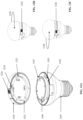
- FIGS. 9 A and 9 B there is shown an embodiment of the base module lighting or smart device of the present invention.
- the modular lighting devices and their internal components described previously herein are capable of use with this embodiment as well.
- FIG. 9 A there is shown the base module 900 which has an end 902 for connection to an electric socket or outlet with electrical contacts as known in the art, a stem section 904 which may be integrally formed or removably attached with the end 902 , and a bulb shaped housing section/area 906 which likewise may be integrally formed with or alternative removably attached to the stem section 904 .
- the end 902 includes threads 903 for connection to electric socket.
- a connector ring 950 which creates a top surface 908 of base module 900 .
- the connector ring 950 aligns with the edge 918 of the bulb shaped area 906 , although other configurations are within the scope of this invention.
- Mount holes 920 may be located on the connector ring 950 for fastening the connector ring piece 950 to the base module 900 .
- Mechanical connections may also be used for connecting the connection ring 950 to base module 900 .
- a female connector area opening 930 is positioned and located on the top surface 908 of the connector piece 950 which receives a male connector from an accessory (as in FIG. 12 ) or another connector piece positioned over the connector ring/piece 950 .
- the locking ring wall 912 Extending from the top surface 908 of connector 950 is the locking ring wall 912 which is surrounded by a locking ring 910 and a contact plate 914 placed on the connector piece 950 , surrounded by and within the locking ring wall 912 .
- the locking ring 910 has at least one and preferably, a pair of key tabs 916 and 917 which are separately positioned from each other, preferably in asymmetrical positions on said ring and asymmetrical in shape as well, with one tab being a different size or shape than the other tab.
- the contact plate 914 has a surface with electrical contacts and data contacts for transfer of power/data to the accessory or to another such connector piece 950 when attached.
- FIG. 9 B illustrates various accessories which can be combined with the base module design and include a limitless variety of functions. These accessories include items such as LED lights, or another connector and locking ring 950 , Bluetooth or camera accessories 952 , speaker or sound systems 954 , or various caps 956 for the lighting and system for aesthetic or functional purposes. Multiple accessories may be added to a base module to increase the functionality by adding connector pieces 950 . (See FIG. 11 ).
- the base module 1000 is shown again and includes an end 1004 for connection to a power outlet and includes threads 1002 for standard mating connections. Typical E26 threads are shown (a U.S. standard), but could be swapped for a variety of other electrical/power connection types based on a standard for the particular geo-location.
- Inside the base module 1000 are the components described earlier, such as the communication component and AC/DC power supply and transfer.
- the base module includes a top end 1008 which includes the connector piece 1009 with locking ring 1010 on the upward extending ring wall 1011 and top surface 1012 with electric/power and/or data contacts.
- the locking features also include a female connector 1034 , which is able to accept and interlock with added accessory modules.
- the female connector 1034 includes a locking slot area 1036 which secures the accessory male connector ( FIG. 12 ).
- the base module 1000 has electrical and data contacts 1016 on the top surface 1012 exposed for module connection, which in this manner passes power to connected modules.
- the set up could also pass data, heat dissipation, connection status, among other information as well.
- a power indicator light 1018 is provided as well on the base module 1000 .
- FIG. 11 there is shown the embodiment of the present invention with multiple accessory pieces attached to the base module 1100 .
- a single accessory 1102 attached to the base module piece 1100 which includes the threads 1104 for electrical connection to a power socket.
- the base module 1100 and the accessory piece 1102 are joined by connection piece 1108 at their respective surfaces allowing for transfer of power and data, audio and video, wi-fi connectivity can be included as well.
- Power indicator light 1106 provides for visual inspection of a proper connection of electric and data when the light is on.
- connection piece 1122 which provides mechanical as well as electrical, and data, audio/video connection as well as wi-fi.
- Attached and connected above the first accessory 1120 is a second accessory 1130 , which may be a different type of accessory than the first accessory 1120 —such as an aesthetically designed light cap.
- the first accessory 1120 and second accessory 1130 have respective connection pieces 1138 and 1140 joining at 1132 to connect power, and data, audio/video from one accessory to the second accessory.
- the added accessory has the ability to interlock into the base module (the size and shape of external shell can vary). This is seen in FIG. 12 , with the asymmetric keying features aligning the modules and accessories.
- the accessory or connector 1220 placed over the base module piece 1200 with connector ring.
- the key tabs 1206 and 1207 of the base module 1200 are received into the appropriate key tab receiving areas 1222 , 1223 of the accessory or connector 1220 , as each key tab 1206 , 1207 may be positioned differently or a different size to ensure the one way locking mechanism.
- the key tab receiving areas 1222 , 1223 are located at a corresponding location on the underside of the accessory/connector 1220 to align with the position of the key tabs 1206 , 1207 .
- Other accessories may be attached in similar manner to the base module 1200 or to other accessories by key tabs and respective receiving areas on the accessories.
- the rotation and locking mechanism described herein are used to align power and communication throughout the lengths of each attached module and accessory and the entire desired assembly as the user includes various modules and accessories.
- the base module 1300 in FIG. 13 has a plurality of electric contact pads 1304 on the top surface 1306 extending from the base module PCB. These one or more electric contact pads 1304 electrically contact, and physically contact, the spring type contacts 1308 located on the surface 1310 of the accessory 1302 .
Landscapes
- Engineering & Computer Science (AREA)
- General Engineering & Computer Science (AREA)
- Microelectronics & Electronic Packaging (AREA)
- Physics & Mathematics (AREA)
- Optics & Photonics (AREA)
- Arrangement Of Elements, Cooling, Sealing, Or The Like Of Lighting Devices (AREA)
- Circuit Arrangement For Electric Light Sources In General (AREA)
Abstract
Description
Claims (10)
Priority Applications (2)
| Application Number | Priority Date | Filing Date | Title |
|---|---|---|---|
| US16/953,259 US12276410B2 (en) | 2019-11-19 | 2020-11-19 | LED light with replaceable module and intelligent connectivity |
| US19/079,198 US20250237373A1 (en) | 2019-11-19 | 2025-03-13 | Led light with replaceable module and intelligent connectivity |
Applications Claiming Priority (2)
| Application Number | Priority Date | Filing Date | Title |
|---|---|---|---|
| US201962937767P | 2019-11-19 | 2019-11-19 | |
| US16/953,259 US12276410B2 (en) | 2019-11-19 | 2020-11-19 | LED light with replaceable module and intelligent connectivity |
Related Child Applications (1)
| Application Number | Title | Priority Date | Filing Date |
|---|---|---|---|
| US19/079,198 Division US20250237373A1 (en) | 2019-11-19 | 2025-03-13 | Led light with replaceable module and intelligent connectivity |
Publications (2)
| Publication Number | Publication Date |
|---|---|
| US20210262648A1 US20210262648A1 (en) | 2021-08-26 |
| US12276410B2 true US12276410B2 (en) | 2025-04-15 |
Family
ID=77366895
Family Applications (2)
| Application Number | Title | Priority Date | Filing Date |
|---|---|---|---|
| US16/953,259 Active US12276410B2 (en) | 2019-11-19 | 2020-11-19 | LED light with replaceable module and intelligent connectivity |
| US19/079,198 Pending US20250237373A1 (en) | 2019-11-19 | 2025-03-13 | Led light with replaceable module and intelligent connectivity |
Family Applications After (1)
| Application Number | Title | Priority Date | Filing Date |
|---|---|---|---|
| US19/079,198 Pending US20250237373A1 (en) | 2019-11-19 | 2025-03-13 | Led light with replaceable module and intelligent connectivity |
Country Status (1)
| Country | Link |
|---|---|
| US (2) | US12276410B2 (en) |
Families Citing this family (2)
| Publication number | Priority date | Publication date | Assignee | Title |
|---|---|---|---|---|
| US11335341B1 (en) * | 2019-01-29 | 2022-05-17 | Ezlo Innovation Llc | Voice orchestrated infrastructure system |
| AU2023254867A1 (en) * | 2023-10-23 | 2025-05-08 | Shawik Pty Ltd | LED Bulb with Photodiode Light Sensor and Microwave Sensor |
Citations (4)
| Publication number | Priority date | Publication date | Assignee | Title |
|---|---|---|---|---|
| US7869974B2 (en) * | 2003-01-15 | 2011-01-11 | Plishner Paul J | Connector or other circuit element having an indirectly coupled integrated circuit |
| US20170108203A1 (en) * | 2015-10-20 | 2017-04-20 | Philippe Georges Habchi | Light bulb |
| US9746138B1 (en) * | 2016-11-24 | 2017-08-29 | John-Michael Dimitro Thomas | Modular lighting and ancillary component apparatus and system |
| US9784417B1 (en) * | 2014-07-21 | 2017-10-10 | Astro, Inc. | Multi-purpose lightbulb |
-
2020
- 2020-11-19 US US16/953,259 patent/US12276410B2/en active Active
-
2025
- 2025-03-13 US US19/079,198 patent/US20250237373A1/en active Pending
Patent Citations (4)
| Publication number | Priority date | Publication date | Assignee | Title |
|---|---|---|---|---|
| US7869974B2 (en) * | 2003-01-15 | 2011-01-11 | Plishner Paul J | Connector or other circuit element having an indirectly coupled integrated circuit |
| US9784417B1 (en) * | 2014-07-21 | 2017-10-10 | Astro, Inc. | Multi-purpose lightbulb |
| US20170108203A1 (en) * | 2015-10-20 | 2017-04-20 | Philippe Georges Habchi | Light bulb |
| US9746138B1 (en) * | 2016-11-24 | 2017-08-29 | John-Michael Dimitro Thomas | Modular lighting and ancillary component apparatus and system |
Also Published As
| Publication number | Publication date |
|---|---|
| US20210262648A1 (en) | 2021-08-26 |
| US20250237373A1 (en) | 2025-07-24 |
Similar Documents
| Publication | Publication Date | Title |
|---|---|---|
| US20250237373A1 (en) | Led light with replaceable module and intelligent connectivity | |
| US9920888B1 (en) | Multi-purpose lightbulb having power failure mode | |
| US9980352B2 (en) | Wireless light pairing, dimming and control | |
| KR102403709B1 (en) | Design for compact home assistant with combined acoustic waveguide and heat sink | |
| JP6359103B2 (en) | System for remote control of controllable devices | |
| US8626318B2 (en) | Lamp device | |
| JP7217571B2 (en) | Commissioning in multi-hop networks with single-hop connections | |
| JP7096256B2 (en) | Device pairing | |
| CN106465514A (en) | Wireless and power line light pairing dimming and control | |
| CN108141713A (en) | Replace the component of the enabling wireless communication in lamps and lanterns | |
| KR20110129906A (en) | Lighting control network | |
| TW202042564A (en) | Framework for handling sensor data in a smart home system | |
| WO2015078778A1 (en) | Zigbee light link network commissioning | |
| CN106102223A (en) | An intelligent lighting control system based on two-dimensional code scanning technology | |
| CN111742610A (en) | Debugging method and apparatus utilizing controlled join mode | |
| US11651774B2 (en) | LED light with replaceable module and intelligent connectivity | |
| JP2017517124A (en) | System and method for pairing multiple peripheral devices using a single entry passkey | |
| US11627012B2 (en) | Home automation management system | |
| KR20150123676A (en) | Wireless communication system and communication method using the system | |
| US11810563B2 (en) | Voice orchestrated infrastructure system | |
| KR20200120986A (en) | Smart lamp for wireless communication and system for controlling smart lamp | |
| EP3782332B1 (en) | Voice assistance device for home automation applications | |
| TWM580216U (en) | Wireless and powerless light voice control system | |
| TWM576767U (en) | Wireless and cordless remote control system | |
| CN205793534U (en) | An intelligent lighting fixture |
Legal Events
| Date | Code | Title | Description |
|---|---|---|---|
| FEPP | Fee payment procedure |
Free format text: ENTITY STATUS SET TO UNDISCOUNTED (ORIGINAL EVENT CODE: BIG.); ENTITY STATUS OF PATENT OWNER: SMALL ENTITY |
|
| FEPP | Fee payment procedure |
Free format text: ENTITY STATUS SET TO SMALL (ORIGINAL EVENT CODE: SMAL); ENTITY STATUS OF PATENT OWNER: SMALL ENTITY |
|
| STPP | Information on status: patent application and granting procedure in general |
Free format text: NON FINAL ACTION MAILED |
|
| STPP | Information on status: patent application and granting procedure in general |
Free format text: RESPONSE TO NON-FINAL OFFICE ACTION ENTERED AND FORWARDED TO EXAMINER |
|
| STPP | Information on status: patent application and granting procedure in general |
Free format text: NON FINAL ACTION MAILED |
|
| STPP | Information on status: patent application and granting procedure in general |
Free format text: RESPONSE TO NON-FINAL OFFICE ACTION ENTERED AND FORWARDED TO EXAMINER |
|
| AS | Assignment |
Owner name: EZLO INNOVATION LLC, NEW JERSEY Free format text: ASSIGNMENT OF ASSIGNORS INTEREST;ASSIGNOR:STACHOWSKI, BREANNA;REEL/FRAME:062178/0042 Effective date: 20211118 |
|
| AS | Assignment |
Owner name: EZLO INNOVATION LLC, NEW JERSEY Free format text: ASSIGNMENT OF ASSIGNORS INTEREST;ASSIGNOR:ABDULHAYOGLU, MELIH;REEL/FRAME:062481/0316 Effective date: 20230124 |
|
| STPP | Information on status: patent application and granting procedure in general |
Free format text: FINAL REJECTION MAILED |
|
| STPP | Information on status: patent application and granting procedure in general |
Free format text: DOCKETED NEW CASE - READY FOR EXAMINATION |
|
| STPP | Information on status: patent application and granting procedure in general |
Free format text: NON FINAL ACTION MAILED |
|
| STPP | Information on status: patent application and granting procedure in general |
Free format text: RESPONSE TO NON-FINAL OFFICE ACTION ENTERED AND FORWARDED TO EXAMINER |
|
| STPP | Information on status: patent application and granting procedure in general |
Free format text: FINAL REJECTION MAILED |
|
| STPP | Information on status: patent application and granting procedure in general |
Free format text: DOCKETED NEW CASE - READY FOR EXAMINATION |
|
| STPP | Information on status: patent application and granting procedure in general |
Free format text: NOTICE OF ALLOWANCE MAILED -- APPLICATION RECEIVED IN OFFICE OF PUBLICATIONS |
|
| STCF | Information on status: patent grant |
Free format text: PATENTED CASE |