US12270520B2 - Vehicle lamp - Google Patents
Vehicle lamp Download PDFInfo
- Publication number
- US12270520B2 US12270520B2 US17/632,738 US202017632738A US12270520B2 US 12270520 B2 US12270520 B2 US 12270520B2 US 202017632738 A US202017632738 A US 202017632738A US 12270520 B2 US12270520 B2 US 12270520B2
- Authority
- US
- United States
- Prior art keywords
- reflector
- light
- light sources
- light source
- reflectors
- Prior art date
- Legal status (The legal status is an assumption and is not a legal conclusion. Google has not performed a legal analysis and makes no representation as to the accuracy of the status listed.)
- Active
Links
Images


Classifications
-
- F—MECHANICAL ENGINEERING; LIGHTING; HEATING; WEAPONS; BLASTING
- F21—LIGHTING
- F21S—NON-PORTABLE LIGHTING DEVICES; SYSTEMS THEREOF; VEHICLE LIGHTING DEVICES SPECIALLY ADAPTED FOR VEHICLE EXTERIORS
- F21S41/00—Illuminating devices specially adapted for vehicle exteriors, e.g. headlamps
- F21S41/10—Illuminating devices specially adapted for vehicle exteriors, e.g. headlamps characterised by the light source
- F21S41/14—Illuminating devices specially adapted for vehicle exteriors, e.g. headlamps characterised by the light source characterised by the type of light source
- F21S41/141—Light emitting diodes [LED]
- F21S41/147—Light emitting diodes [LED] the main emission direction of the LED being angled to the optical axis of the illuminating device
-
- F—MECHANICAL ENGINEERING; LIGHTING; HEATING; WEAPONS; BLASTING
- F21—LIGHTING
- F21S—NON-PORTABLE LIGHTING DEVICES; SYSTEMS THEREOF; VEHICLE LIGHTING DEVICES SPECIALLY ADAPTED FOR VEHICLE EXTERIORS
- F21S41/00—Illuminating devices specially adapted for vehicle exteriors, e.g. headlamps
- F21S41/30—Illuminating devices specially adapted for vehicle exteriors, e.g. headlamps characterised by reflectors
- F21S41/32—Optical layout thereof
-
- F—MECHANICAL ENGINEERING; LIGHTING; HEATING; WEAPONS; BLASTING
- F21—LIGHTING
- F21S—NON-PORTABLE LIGHTING DEVICES; SYSTEMS THEREOF; VEHICLE LIGHTING DEVICES SPECIALLY ADAPTED FOR VEHICLE EXTERIORS
- F21S41/00—Illuminating devices specially adapted for vehicle exteriors, e.g. headlamps
- F21S41/10—Illuminating devices specially adapted for vehicle exteriors, e.g. headlamps characterised by the light source
- F21S41/14—Illuminating devices specially adapted for vehicle exteriors, e.g. headlamps characterised by the light source characterised by the type of light source
- F21S41/141—Light emitting diodes [LED]
- F21S41/151—Light emitting diodes [LED] arranged in one or more lines
-
- F—MECHANICAL ENGINEERING; LIGHTING; HEATING; WEAPONS; BLASTING
- F21—LIGHTING
- F21S—NON-PORTABLE LIGHTING DEVICES; SYSTEMS THEREOF; VEHICLE LIGHTING DEVICES SPECIALLY ADAPTED FOR VEHICLE EXTERIORS
- F21S41/00—Illuminating devices specially adapted for vehicle exteriors, e.g. headlamps
- F21S41/30—Illuminating devices specially adapted for vehicle exteriors, e.g. headlamps characterised by reflectors
- F21S41/32—Optical layout thereof
- F21S41/36—Combinations of two or more separate reflectors
-
- F—MECHANICAL ENGINEERING; LIGHTING; HEATING; WEAPONS; BLASTING
- F21—LIGHTING
- F21S—NON-PORTABLE LIGHTING DEVICES; SYSTEMS THEREOF; VEHICLE LIGHTING DEVICES SPECIALLY ADAPTED FOR VEHICLE EXTERIORS
- F21S41/00—Illuminating devices specially adapted for vehicle exteriors, e.g. headlamps
- F21S41/60—Illuminating devices specially adapted for vehicle exteriors, e.g. headlamps characterised by a variable light distribution
- F21S41/65—Illuminating devices specially adapted for vehicle exteriors, e.g. headlamps characterised by a variable light distribution by acting on light sources
- F21S41/663—Illuminating devices specially adapted for vehicle exteriors, e.g. headlamps characterised by a variable light distribution by acting on light sources by switching light sources
-
- F—MECHANICAL ENGINEERING; LIGHTING; HEATING; WEAPONS; BLASTING
- F21—LIGHTING
- F21S—NON-PORTABLE LIGHTING DEVICES; SYSTEMS THEREOF; VEHICLE LIGHTING DEVICES SPECIALLY ADAPTED FOR VEHICLE EXTERIORS
- F21S41/00—Illuminating devices specially adapted for vehicle exteriors, e.g. headlamps
- F21S41/10—Illuminating devices specially adapted for vehicle exteriors, e.g. headlamps characterised by the light source
- F21S41/14—Illuminating devices specially adapted for vehicle exteriors, e.g. headlamps characterised by the light source characterised by the type of light source
- F21S41/141—Light emitting diodes [LED]
- F21S41/151—Light emitting diodes [LED] arranged in one or more lines
- F21S41/153—Light emitting diodes [LED] arranged in one or more lines arranged in a matrix
-
- F—MECHANICAL ENGINEERING; LIGHTING; HEATING; WEAPONS; BLASTING
- F21—LIGHTING
- F21S—NON-PORTABLE LIGHTING DEVICES; SYSTEMS THEREOF; VEHICLE LIGHTING DEVICES SPECIALLY ADAPTED FOR VEHICLE EXTERIORS
- F21S41/00—Illuminating devices specially adapted for vehicle exteriors, e.g. headlamps
- F21S41/30—Illuminating devices specially adapted for vehicle exteriors, e.g. headlamps characterised by reflectors
- F21S41/32—Optical layout thereof
- F21S41/33—Multi-surface reflectors, e.g. reflectors with facets or reflectors with portions of different curvature
- F21S41/331—Multi-surface reflectors, e.g. reflectors with facets or reflectors with portions of different curvature the reflector consisting of complete annular areas
- F21S41/332—Multi-surface reflectors, e.g. reflectors with facets or reflectors with portions of different curvature the reflector consisting of complete annular areas with continuity at the junction between adjacent areas
-
- F—MECHANICAL ENGINEERING; LIGHTING; HEATING; WEAPONS; BLASTING
- F21—LIGHTING
- F21S—NON-PORTABLE LIGHTING DEVICES; SYSTEMS THEREOF; VEHICLE LIGHTING DEVICES SPECIALLY ADAPTED FOR VEHICLE EXTERIORS
- F21S41/00—Illuminating devices specially adapted for vehicle exteriors, e.g. headlamps
- F21S41/30—Illuminating devices specially adapted for vehicle exteriors, e.g. headlamps characterised by reflectors
- F21S41/32—Optical layout thereof
- F21S41/33—Multi-surface reflectors, e.g. reflectors with facets or reflectors with portions of different curvature
- F21S41/331—Multi-surface reflectors, e.g. reflectors with facets or reflectors with portions of different curvature the reflector consisting of complete annular areas
- F21S41/333—Multi-surface reflectors, e.g. reflectors with facets or reflectors with portions of different curvature the reflector consisting of complete annular areas with discontinuity at the junction between adjacent areas
-
- F—MECHANICAL ENGINEERING; LIGHTING; HEATING; WEAPONS; BLASTING
- F21—LIGHTING
- F21S—NON-PORTABLE LIGHTING DEVICES; SYSTEMS THEREOF; VEHICLE LIGHTING DEVICES SPECIALLY ADAPTED FOR VEHICLE EXTERIORS
- F21S41/00—Illuminating devices specially adapted for vehicle exteriors, e.g. headlamps
- F21S41/30—Illuminating devices specially adapted for vehicle exteriors, e.g. headlamps characterised by reflectors
- F21S41/32—Optical layout thereof
- F21S41/33—Multi-surface reflectors, e.g. reflectors with facets or reflectors with portions of different curvature
- F21S41/334—Multi-surface reflectors, e.g. reflectors with facets or reflectors with portions of different curvature the reflector consisting of patch like sectors
- F21S41/335—Multi-surface reflectors, e.g. reflectors with facets or reflectors with portions of different curvature the reflector consisting of patch like sectors with continuity at the junction between adjacent areas
-
- F—MECHANICAL ENGINEERING; LIGHTING; HEATING; WEAPONS; BLASTING
- F21—LIGHTING
- F21S—NON-PORTABLE LIGHTING DEVICES; SYSTEMS THEREOF; VEHICLE LIGHTING DEVICES SPECIALLY ADAPTED FOR VEHICLE EXTERIORS
- F21S41/00—Illuminating devices specially adapted for vehicle exteriors, e.g. headlamps
- F21S41/30—Illuminating devices specially adapted for vehicle exteriors, e.g. headlamps characterised by reflectors
- F21S41/32—Optical layout thereof
- F21S41/33—Multi-surface reflectors, e.g. reflectors with facets or reflectors with portions of different curvature
- F21S41/334—Multi-surface reflectors, e.g. reflectors with facets or reflectors with portions of different curvature the reflector consisting of patch like sectors
- F21S41/336—Multi-surface reflectors, e.g. reflectors with facets or reflectors with portions of different curvature the reflector consisting of patch like sectors with discontinuity at the junction between adjacent areas
-
- F—MECHANICAL ENGINEERING; LIGHTING; HEATING; WEAPONS; BLASTING
- F21—LIGHTING
- F21S—NON-PORTABLE LIGHTING DEVICES; SYSTEMS THEREOF; VEHICLE LIGHTING DEVICES SPECIALLY ADAPTED FOR VEHICLE EXTERIORS
- F21S41/00—Illuminating devices specially adapted for vehicle exteriors, e.g. headlamps
- F21S41/30—Illuminating devices specially adapted for vehicle exteriors, e.g. headlamps characterised by reflectors
- F21S41/32—Optical layout thereof
- F21S41/33—Multi-surface reflectors, e.g. reflectors with facets or reflectors with portions of different curvature
- F21S41/337—Multi-surface reflectors, e.g. reflectors with facets or reflectors with portions of different curvature the reflector having a structured surface, e.g. with facets or corrugations
-
- F—MECHANICAL ENGINEERING; LIGHTING; HEATING; WEAPONS; BLASTING
- F21—LIGHTING
- F21S—NON-PORTABLE LIGHTING DEVICES; SYSTEMS THEREOF; VEHICLE LIGHTING DEVICES SPECIALLY ADAPTED FOR VEHICLE EXTERIORS
- F21S41/00—Illuminating devices specially adapted for vehicle exteriors, e.g. headlamps
- F21S41/30—Illuminating devices specially adapted for vehicle exteriors, e.g. headlamps characterised by reflectors
- F21S41/32—Optical layout thereof
- F21S41/33—Multi-surface reflectors, e.g. reflectors with facets or reflectors with portions of different curvature
- F21S41/338—Multi-surface reflectors, e.g. reflectors with facets or reflectors with portions of different curvature the reflector having surface portions added to its general concavity
-
- F—MECHANICAL ENGINEERING; LIGHTING; HEATING; WEAPONS; BLASTING
- F21—LIGHTING
- F21W—INDEXING SCHEME ASSOCIATED WITH SUBCLASSES F21K, F21L, F21S and F21V, RELATING TO USES OR APPLICATIONS OF LIGHTING DEVICES OR SYSTEMS
- F21W2102/00—Exterior vehicle lighting devices for illuminating purposes
-
- F—MECHANICAL ENGINEERING; LIGHTING; HEATING; WEAPONS; BLASTING
- F21—LIGHTING
- F21W—INDEXING SCHEME ASSOCIATED WITH SUBCLASSES F21K, F21L, F21S and F21V, RELATING TO USES OR APPLICATIONS OF LIGHTING DEVICES OR SYSTEMS
- F21W2102/00—Exterior vehicle lighting devices for illuminating purposes
- F21W2102/10—Arrangement or contour of the emitted light
- F21W2102/13—Arrangement or contour of the emitted light for high-beam region or low-beam region
- F21W2102/135—Arrangement or contour of the emitted light for high-beam region or low-beam region the light having cut-off lines, i.e. clear borderlines between emitted regions and dark regions
- F21W2102/14—Arrangement or contour of the emitted light for high-beam region or low-beam region the light having cut-off lines, i.e. clear borderlines between emitted regions and dark regions having vertical cut-off lines; specially adapted for adaptive high beams, i.e. wherein the beam is broader but avoids glaring other road users
- F21W2102/145—Arrangement or contour of the emitted light for high-beam region or low-beam region the light having cut-off lines, i.e. clear borderlines between emitted regions and dark regions having vertical cut-off lines; specially adapted for adaptive high beams, i.e. wherein the beam is broader but avoids glaring other road users wherein the light is emitted between two parallel vertical cutoff lines, e.g. selectively emitted rectangular-shaped high beam
-
- F—MECHANICAL ENGINEERING; LIGHTING; HEATING; WEAPONS; BLASTING
- F21—LIGHTING
- F21W—INDEXING SCHEME ASSOCIATED WITH SUBCLASSES F21K, F21L, F21S and F21V, RELATING TO USES OR APPLICATIONS OF LIGHTING DEVICES OR SYSTEMS
- F21W2102/00—Exterior vehicle lighting devices for illuminating purposes
- F21W2102/10—Arrangement or contour of the emitted light
- F21W2102/13—Arrangement or contour of the emitted light for high-beam region or low-beam region
- F21W2102/135—Arrangement or contour of the emitted light for high-beam region or low-beam region the light having cut-off lines, i.e. clear borderlines between emitted regions and dark regions
- F21W2102/14—Arrangement or contour of the emitted light for high-beam region or low-beam region the light having cut-off lines, i.e. clear borderlines between emitted regions and dark regions having vertical cut-off lines; specially adapted for adaptive high beams, i.e. wherein the beam is broader but avoids glaring other road users
- F21W2102/15—Arrangement or contour of the emitted light for high-beam region or low-beam region the light having cut-off lines, i.e. clear borderlines between emitted regions and dark regions having vertical cut-off lines; specially adapted for adaptive high beams, i.e. wherein the beam is broader but avoids glaring other road users wherein the light is emitted under L-shaped cut-off lines, i.e. vertical and horizontal cutoff lines
-
- F—MECHANICAL ENGINEERING; LIGHTING; HEATING; WEAPONS; BLASTING
- F21—LIGHTING
- F21W—INDEXING SCHEME ASSOCIATED WITH SUBCLASSES F21K, F21L, F21S and F21V, RELATING TO USES OR APPLICATIONS OF LIGHTING DEVICES OR SYSTEMS
- F21W2102/00—Exterior vehicle lighting devices for illuminating purposes
- F21W2102/10—Arrangement or contour of the emitted light
- F21W2102/13—Arrangement or contour of the emitted light for high-beam region or low-beam region
- F21W2102/135—Arrangement or contour of the emitted light for high-beam region or low-beam region the light having cut-off lines, i.e. clear borderlines between emitted regions and dark regions
- F21W2102/155—Arrangement or contour of the emitted light for high-beam region or low-beam region the light having cut-off lines, i.e. clear borderlines between emitted regions and dark regions having inclined and horizontal cutoff lines
-
- F—MECHANICAL ENGINEERING; LIGHTING; HEATING; WEAPONS; BLASTING
- F21—LIGHTING
- F21W—INDEXING SCHEME ASSOCIATED WITH SUBCLASSES F21K, F21L, F21S and F21V, RELATING TO USES OR APPLICATIONS OF LIGHTING DEVICES OR SYSTEMS
- F21W2102/00—Exterior vehicle lighting devices for illuminating purposes
- F21W2102/10—Arrangement or contour of the emitted light
- F21W2102/13—Arrangement or contour of the emitted light for high-beam region or low-beam region
- F21W2102/135—Arrangement or contour of the emitted light for high-beam region or low-beam region the light having cut-off lines, i.e. clear borderlines between emitted regions and dark regions
- F21W2102/16—Arrangement or contour of the emitted light for high-beam region or low-beam region the light having cut-off lines, i.e. clear borderlines between emitted regions and dark regions having blurred cut-off lines
-
- F—MECHANICAL ENGINEERING; LIGHTING; HEATING; WEAPONS; BLASTING
- F21—LIGHTING
- F21W—INDEXING SCHEME ASSOCIATED WITH SUBCLASSES F21K, F21L, F21S and F21V, RELATING TO USES OR APPLICATIONS OF LIGHTING DEVICES OR SYSTEMS
- F21W2102/00—Exterior vehicle lighting devices for illuminating purposes
- F21W2102/10—Arrangement or contour of the emitted light
- F21W2102/13—Arrangement or contour of the emitted light for high-beam region or low-beam region
- F21W2102/165—Arrangement or contour of the emitted light for high-beam region or low-beam region the borderlines between emitted regions and dark regions other than cut-off lines being variable
-
- F—MECHANICAL ENGINEERING; LIGHTING; HEATING; WEAPONS; BLASTING
- F21—LIGHTING
- F21W—INDEXING SCHEME ASSOCIATED WITH SUBCLASSES F21K, F21L, F21S and F21V, RELATING TO USES OR APPLICATIONS OF LIGHTING DEVICES OR SYSTEMS
- F21W2102/00—Exterior vehicle lighting devices for illuminating purposes
- F21W2102/10—Arrangement or contour of the emitted light
- F21W2102/17—Arrangement or contour of the emitted light for regions other than high beam or low beam
- F21W2102/18—Arrangement or contour of the emitted light for regions other than high beam or low beam for overhead signs
-
- F—MECHANICAL ENGINEERING; LIGHTING; HEATING; WEAPONS; BLASTING
- F21—LIGHTING
- F21W—INDEXING SCHEME ASSOCIATED WITH SUBCLASSES F21K, F21L, F21S and F21V, RELATING TO USES OR APPLICATIONS OF LIGHTING DEVICES OR SYSTEMS
- F21W2102/00—Exterior vehicle lighting devices for illuminating purposes
- F21W2102/10—Arrangement or contour of the emitted light
- F21W2102/17—Arrangement or contour of the emitted light for regions other than high beam or low beam
- F21W2102/19—Arrangement or contour of the emitted light for regions other than high beam or low beam for curves
-
- F—MECHANICAL ENGINEERING; LIGHTING; HEATING; WEAPONS; BLASTING
- F21—LIGHTING
- F21W—INDEXING SCHEME ASSOCIATED WITH SUBCLASSES F21K, F21L, F21S and F21V, RELATING TO USES OR APPLICATIONS OF LIGHTING DEVICES OR SYSTEMS
- F21W2102/00—Exterior vehicle lighting devices for illuminating purposes
- F21W2102/20—Illuminance distribution within the emitted light
-
- F—MECHANICAL ENGINEERING; LIGHTING; HEATING; WEAPONS; BLASTING
- F21—LIGHTING
- F21W—INDEXING SCHEME ASSOCIATED WITH SUBCLASSES F21K, F21L, F21S and F21V, RELATING TO USES OR APPLICATIONS OF LIGHTING DEVICES OR SYSTEMS
- F21W2102/00—Exterior vehicle lighting devices for illuminating purposes
- F21W2102/30—Fog lights
-
- F—MECHANICAL ENGINEERING; LIGHTING; HEATING; WEAPONS; BLASTING
- F21—LIGHTING
- F21W—INDEXING SCHEME ASSOCIATED WITH SUBCLASSES F21K, F21L, F21S and F21V, RELATING TO USES OR APPLICATIONS OF LIGHTING DEVICES OR SYSTEMS
- F21W2102/00—Exterior vehicle lighting devices for illuminating purposes
- F21W2102/40—Exterior vehicle lighting devices for illuminating purposes the light being emitted to facilitate access to the vehicle
-
- F—MECHANICAL ENGINEERING; LIGHTING; HEATING; WEAPONS; BLASTING
- F21—LIGHTING
- F21W—INDEXING SCHEME ASSOCIATED WITH SUBCLASSES F21K, F21L, F21S and F21V, RELATING TO USES OR APPLICATIONS OF LIGHTING DEVICES OR SYSTEMS
- F21W2107/00—Use or application of lighting devices on or in particular types of vehicles
- F21W2107/10—Use or application of lighting devices on or in particular types of vehicles for land vehicles
Definitions
- the present invention relates to a vehicle lamp.
- a vehicle lamp including a light source including a plurality of semiconductor light emitting elements that can be individually turned on and off, and a reflector having a reflective surface based on a rotating parabolic surface, wherein the reflector includes a plurality of partial reflectors divided in the vertical direction, and the reflective surface of each partial reflector is configured such that the horizontal spread of reflected light on a predetermined projection surface reflected by each partial reflector is substantially equal (see PTL 1, for example).
- a vehicle lamp including: a plurality of reflectors including a first reflector; and a plurality of light sources provided in the plurality of reflectors in a mode in which at least one of the plurality of light sources is provided in each of the plurality of reflectors, wherein the plurality of light sources include two or more first light sources provided in the first reflector, a light distribution pattern of light emitted from the plurality of light sources through the plurality of reflectors includes a first pattern in which a width in a vertical direction decreases toward a vehicle outer side, one of the two or more first light sources is disposed at a focal point of the first reflector, and the other of the two or more first light sources is disposed on a vehicle inner side with respect to the focal point of the first reflector.
- the present invention it is possible to reduce glare caused by light irradiation to a reflection object such as a signboard located on the roadway lateral side, in a vehicle lamp provided with a plurality of reflectors.
- FIG. 1 is a plan view of a vehicle provided with vehicle lamps of this embodiment.
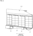
- FIG. 2 is a front view for illustrating a reflector assembly of a lamp unit of an embodiment.
- FIG. 3 is a top view illustrating relationship between reflectors and light sources of the lamp unit.
- FIG. 4 is a system diagram schematically illustrating a control system according to the light sources of the lamp unit.
- FIG. 5 is an explanatory diagram of an example of a light distribution pattern of the lamp unit.
- FIG. 6 is an explanatory diagram of another example of the light distribution pattern of the lamp unit.
- FIG. 7 is a diagram illustrating a light distribution pattern realized by the second reflector 21 and the second light source 31 .
- FIG. 8 is a diagram illustrating a light distribution pattern realized by the first reflector 22 and the first light source 32 .
- FIG. 9 is a diagram illustrating a light distribution pattern realized by the first reflector 22 and the first light source 33 .
- FIG. 10 is a diagram illustrating a light distribution pattern realized by the third reflector 23 and the third light source 34 .
- FIG. 11 is a diagram illustrating a light distribution pattern realized by the third reflector 23 and the third light source 35 .
- FIG. 12 is a diagram illustrating a light distribution pattern realized by the fourth reflector 24 and the fourth light source 36 .
- FIG. 13 A is an explanatory diagram of an example of a light distribution pattern realized by the first reflector 22 and the first light sources 32 and 33 .
- FIG. 13 B is an explanatory diagram of another example of the light distribution pattern realized by the first reflector 22 and the first light sources 32 and 33 .
- FIG. 14 A is an explanatory diagram of an example of a light distribution pattern realized by the third reflector 23 and the third light sources 34 and 35 .
- FIG. 14 B is an explanatory diagram of another example of the light distribution pattern realized by the third reflector 23 and the third light sources 34 and 35 .
- FIG. 15 A is a diagram illustrating a light distribution pattern in a case where all the light sources are turned on.
- FIG. 15 B is a diagram illustrating a light distribution pattern in a case where some of the light sources are turned on.
- FIG. 15 C is a diagram illustrating a light distribution pattern in a case where some of the light sources are turned on.
- FIG. 15 D is a diagram illustrating a light distribution pattern in a case where some of the other light sources are turned on.
- FIG. 15 E is a diagram illustrating a light distribution pattern in a case where some of the other light sources are turned on.
- FIG. 16 is a top view illustrating relationship between reflectors and light sources of a lamp unit as a second embodiment.
- the vehicle outer side refers to the outer side of the vehicle in the left-right direction with respect to the front-rear axis of the vehicle that passes through the center of the vehicle in the left-right direction
- the vehicle inner side refers to the side closer to the front-rear axis in the left-right direction of the vehicle.
- the vehicle lamps of this embodiment are respective vehicle headlights ( 101 L, 101 R) provided on the left and right sides of the front side of the vehicle 102 , and will be hereinafter simply referred to as vehicle lamps.
- Each of the vehicle lamps in this embodiment includes a housing (not illustrated) with an opening on the front side of the vehicle and an outer lens (not illustrated) attached to the housing so as to cover the opening, and a lamp unit 1 (see FIG. 2 ) and the like are disposed in a lamp chamber formed by the housing and the outer lens.
- the lamp unit 1 of the right headlight 101 R will be described with reference to FIG. 2 and subsequent drawings. Unless otherwise mentioned, the same may be described for the lamp unit 1 of the left headlight 101 L.
- the lamp unit 1 of the left headlight 101 L has a symmetrical configuration with respect to the lamp unit 1 of the right headlight 101 R.
- FIG. 2 is a front view for illustrating a reflector assembly 20 of the lamp unit 1 of an embodiment.
- the lamp unit 1 is an ADB (Adaptive Driving Beam) or high beam, and includes the reflector assembly 20 .
- the reflector assembly 20 includes four reflectors 21 to 24 aligned in the vehicle width direction.
- the first reflector 22 is located on the vehicle outer side with respect to the second reflector 21 .
- the second reflector 21 is located on the vehicle innermost side among the four reflectors 21 to 24
- the third reflector 23 is located on the vehicle outer side with respect to the first reflector 22 .
- the fourth reflector 24 is located on the vehicle outer side with respect to the third reflector 23 , and is located on the vehicle outermost side among the four reflectors 21 to 24 .
- the first reflector 22 is located on the vehicle rear side with respect to the second reflector 21 .
- the second reflector 21 is located on the vehicle foremost side among the four reflectors 21 to 24
- the third reflector 23 is located on the vehicle rear side with respect to the first reflector 22 .
- the fourth reflector 24 is located on the vehicle rear side with respect to the third reflector 23 , and is located on the vehicle rearmost side among the four reflectors 21 to 24 .
- FIG. 3 is a top view illustrating relationship between the reflectors 21 to 24 and light sources 31 to 36 of the lamp unit 1 .
- the outline of the reflectors 21 to 24 is schematically illustrated, and respective focal points of the reflectors 21 to 24 are illustrated by respective intersections O of cross hairs.
- the reflectors 21 to 24 are provided with the light sources 31 to 36 .
- the light sources 31 to 36 are formed of LEDs (Light Emitting Diodes).
- the reflectors 21 to 24 form a traveling light distribution area in front of the vehicle on the basis of light from the light sources 31 to 36 .
- the first light sources 32 and 33 are provided in the first reflector 22 .
- the first light sources 32 and 33 are disposed on the left and right side by side, respectively, and the first light source 32 is disposed on the vehicle inner side with respect to the first light source 33 .
- the first light source 33 is disposed at the focal point of the first reflector 22 .
- the concept of “the first light source 33 is disposed at the focal point of the first reflector 22 ” includes not only a mode in which the center position (center of a chip) of the first light source 33 coincides with the focal point of the first reflector 22 but also a mode in which a chip pertaining to the first light source 33 is located on the focal point of the first reflector 22 . This is substantially the same as the relationship between the light sources and the reflectors other than the first light source 33 and the first reflector 22 .
- the third light sources 34 and 35 are provided in the third reflector 23 .
- the third light sources 34 and 35 are disposed on the left and right side by side, respectively, and the third light source 34 is disposed on the vehicle inner side with respect to the third light source 35 .
- the third light source 35 is disposed at the focal point of the third reflector 23 .
- the second light source 31 is in the form of a single chip integrally mounted with two LED devices, and is provided in the second reflector 21 . As illustrated in FIG. 3 , the second light source 31 is disposed at the focal point of the second reflector 21 in such a mode that the light-emitting chips are adjacent to each other. Note that the concept of “the second light source 31 is disposed at the focal point of the second reflector 21 ” includes not only a mode in which the center position (center between the two LED devices, namely the center of a chip pertaining to the second light source 31 ) of the second light source 31 coincides with the focal point of the second reflector 21 but also a mode in which the chip pertaining to the second light source 31 is located on the focal point of the second reflector 21 .
- the fourth light source 36 is provided in the fourth reflector 24 .
- the fourth light source 36 is disposed at the focal point of the fourth reflector 24 .
- FIG. 4 is a system diagram schematically illustrating a control system 40 for the light sources 31 to 36 of the lamp unit 1 .
- the control system 40 is electrically connected to the light sources 31 to 36 so as to enable individual control of the light sources 31 to 36 .
- the control system 40 includes a microcomputer 400 (referred to as a “microcomputer” in FIG. 4 ) and drive circuits 401 to 406 .
- the microcomputer 400 and the drive circuits 401 to 406 may be embodied as, for example, an ECU (Electronic Control Unit).
- the drive circuit 401 drives the second light source 31 in response to a command from the microcomputer 400 .
- the drive circuit 402 drives the first light source 32 in response to a command from the microcomputer 400 .
- the drive circuits 403 to 406 drive the light sources 33 to 36 , respectively, in response to respective commands from the microcomputer 400 .
- a driving method is pulse driving, and each of the light sources 31 to 36 is individually controlled, for example, in a mode in which the duty ratio of the pulse driving is variable.
- the microcomputer 400 realizes variable light distribution control such as ADB.
- the microcomputer 400 controls the light sources 31 to 36 such that a light distribution pattern that does not cause glare to a driver of an oncoming vehicle or the like is realized on the basis of an image captured from a front camera 50 that captures an image in front of the vehicle.
- variable light distribution control can be realized without using mechanical moving parts.
- the four reflectors 21 to 24 are provided, and therefore a variety of light distribution patterns can be realized.
- various light distribution patterns can be realized by changing the reflector to be used (i.e., the light source to be turned on among the light sources 31 to 36 ) among the four reflectors 21 to 24 (see FIG. 15 A to FIG. 15 E below).
- the brightness (luminous flux) of light sources 31 to 36 can be varied by varying the duty ratio of a drive current, and therefore the brightness of the light sources 31 to 36 can be individually controlled to achieve various light distribution patterns.
- first reflectors 22 and 23 each include the two light sources in one reflector (for example, the first light sources 32 and 33 for the first reflector 22 ), and therefore various light distribution patterns can be realized by changing the light sources to be used.
- FIG. 5 and FIG. 6 are diagrams each schematically illustrating, as a light distribution pattern of the lamp unit 1 , the distribution of the luminous intensity (cross-sectional luminous intensity) on a plane (screen) perpendicular to the optical axis of the lamp unit 1 in front of the vehicle.
- a line V indicates a vertical reference line (V-V line) on the screen
- a line H indicates a horizontal reference line (H-H line) on the screen.
- contour lines L 1 to L 8 of the luminous intensity are illustrated.
- the luminous intensity has the relationship of L 1 >L 2 >L 3 >L 4 >L 5 >L 6 >L 7 >L 8 , and an area surrounded by the contour line L 1 is a so-called “hot zone”.
- the contour line L 8 is a line of 625 [cd], for example, and the contour line L 1 is a line of 50000 [cd].
- description related to the light distribution pattern is description related to a pattern expressed by the luminous intensity as illustrated in FIG. 5 and FIG. 6 .
- FIG. 5 illustrates a light distribution pattern obtained when the light sources 31 to 36 are driven at the following duty ratios.
- the normal pattern is a form in which the width in the vertical direction decreases toward the vehicle outer side, as illustrated in FIG. 5 and FIG. 6 .
- Such a light distribution pattern is hereinafter also referred to as a “light distribution pattern in which the vertical width is reduced on the vehicle outer side.
- glare to a driver may occur due to irradiation of light to a reflection object such as a signboard located on the roadway lateral side because light in an upper portion on the vehicle outer side is relatively strong as described above.
- the light in the upper portion on the vehicle outer side is relatively weak (is on the outer side with respect to the contour line L 8 ) as illustrated in a Q 1 section in each of FIG. 5 and FIG. 6 , and therefore it is possible to reduce an inconvenience (glare to the driver) caused by the irradiation of the light to the reflective objects such as the signboard located on the roadway lateral side.
- a signboard located at a position close to the vehicle tends to be located in the Q 1 section, and according to this embodiment, it is possible to effectively reduce glare caused by reflected light from such a signboard.
- the normal pattern illustrated in FIG. 5 compared to the normal pattern illustrated in FIG. 5 , the area with the highest luminous intensity (“hot zone”) tends to move to the vehicle outer side (i.e., tend to spread outward from the line V or to move away from the line V). Therefore, in this respect, the normal pattern illustrated in FIG. 5 is more advantageous than the normal pattern illustrated in FIG. 6 In addition, the duty ratio when driving the first light source 32 and the like is smaller, and therefore the normal pattern illustrated in FIG. 5 is more advantageous in terms of power consumption than the normal pattern illustrated in FIG. 6 .
- the first light source 32 is preferably caused to emit light having a lower luminous flux than the first light source 33
- the third light source 34 is caused to emit light having a lower luminous flux than the third light source 35 or light having a luminous flux equivalent to that of the first light source 32 .
- the first light source 33 is driven at a duty ratio of 80% and the first light source 32 is driven at a duty ratio of 60%, so that the luminous flux of the first light source 32 is lower than that of the first light source 33 , but is not limited to this.
- the first light source 33 may be driven at a duty ratio of 90% and the first light source 32 may be driven at a duty ratio of 70%.
- a specific value of the duty ratio is an adaptive value. This is also true of the relationship between the third light source 34 and the third light source 35 .
- a method of making the luminous flux of the first light source 32 lower than that of the first light source 33 may be a method other than a method for setting a difference in the duty ratio.
- a difference may be set in rated output itself between the first light source 32 and the first light source 33 . This is also true of the relationship between the third light source 34 and the third light source 35 .
- FIG. 7 is a diagram illustrating a light distribution pattern realized by the second reflector 21 and the second light source 31
- FIG. 8 is a diagram illustrating a light distribution pattern realized by the first reflector 22 and the first light source 32
- FIG. 9 is a diagram illustrating a light distribution pattern realized by the first reflector 22 and the first light source 33
- FIG. 10 is a diagram illustrating a light distribution pattern realized by the third reflector 23 and the third light source 34
- FIG. 11 is a diagram illustrating a light distribution pattern realized by the third reflector 23 and the third light source 35
- FIG. 12 is a diagram illustrating a light distribution pattern realized by the fourth reflector 24 and the fourth light source 36 .
- the lines V and H and the contour lines L 1 to L 8 are described above.
- a condensing portion pertaining to the contour line L 1 is formed at an intersection of the line V and the line H. Consequently, in the normal pattern, the area with the highest luminous intensity (“hot zone”) can be effectively formed at the intersection of the line V and the line H by the second reflector 21 and the second light source 31 .
- the light distribution pattern realized by the first reflector 22 and the first light source 32 is different from the light distribution pattern realized by the first reflector 22 and the first light source 33 in that there is no condensing portion pertaining to the contour line L 3 .
- the light distribution pattern realized by the first reflector 22 and the first light source 32 is in a form in which the vehicle outer side is covered, compared to the light distribution pattern realized by the first reflector 22 and the first light source 33 .
- the first light source 33 is disposed at the focal point of the first reflector 22 , as described above, and therefore it is possible to effectively form the condensing portion pertaining to the contour line L 3 .
- the condensing portion pertaining to the contour line L 3 caused by the first light source 33 is adjacent to a condensing portion pertaining to the contour line L 1 in the light distribution pattern realized by the second reflector 21 and the second light source 31 illustrated in FIG. 7 , from the vehicle outer side. Consequently, it is possible to effectively form the “hot zone” in the normal pattern illustrated in FIG. 5 .
- the light distribution pattern realized by the first reflector 22 and the first light source 33 is different from the light distribution pattern realized by the second reflector 21 and the second light source 31 (see FIG. 7 ) in that there is no condensing portion pertaining to the contour line L 1 .
- the second light source 31 is composed of two LED chips and the first light source 33 composed of one LED chip has a lower luminous flux than the second light source 31 .
- the first light source 32 is disposed on the vehicle inner side with respect to the first light source 33 , as described above. In other words, the first light source 32 is disposed significantly on the vehicle inner side with respect to the focal point of the first reflector 22 . Consequently, it is possible to efficiently realize diffusion of light to the vehicle outer side.
- the light distribution pattern realized by the first reflector 22 and the first light source 32 is a form in which the width in the vertical direction reduces toward the vehicle outer side, as illustrated in FIG. 8 . Consequently, it is possible to effectively realize the light distribution pattern in which the vertical width is reduced on the above vehicle outer side.
- the condensing portion pertaining to the contour line L 4 is located on the vehicle outer side, compared to the light distribution pattern realized by the third reflector 23 and the third light source 35 .
- the light distribution pattern realized by the third reflector 23 and the third light source 34 is in a form in which the vehicle outer side is covered, compared to the light distribution pattern realized by the third reflector 23 and the third light source 35 .
- the third light source 35 is disposed at the focal point of the third reflector 23 , as described above, and therefore it is possible to effectively form the condensing portion pertaining to the contour line L 4 .
- the condensing portion pertaining to the contour line L 4 caused by the third light source 35 is adjacent to the condensing portion pertaining to the contour line L 3 in the light distribution pattern realized by the first reflector 22 and the first light source 33 illustrated in FIG. 9 , from the vehicle outer side.
- the light distribution pattern realized by the third reflector 23 and the third light source 35 is different from the light distribution pattern realized by the first reflector 22 and the first light source 33 (see FIG. 9 ) in that there is no condensing portion pertaining to the contour line L 3 , as illustrated in FIG. 11 . Consequently, the area with the highest luminous intensity can be inhibited from relatively widely extending up to the vehicle outer side.
- the third light source 34 is disposed on the vehicle inner side with respect to the third light source 35 , as described above. In other words, the third light source 34 is disposed significantly on the vehicle inner side with respect to the focal point of the third reflector 23 . Consequently, it is possible to efficiently realize diffusion of light to the vehicle outer side.
- the light distribution pattern realized by the third reflector 23 and the third light source 34 is in a form in which the width in the vertical direction decreases toward the vehicle outer side, as illustrated in FIG. 10 . Consequently, it is possible to effectively realize the light distribution pattern in which the vertical width is reduced on the above vehicle outer side.
- the light distribution pattern realized by the fourth reflector 24 and the fourth light source 36 is different from the light distribution pattern realized by the third reflector 23 and the third light source 34 (see FIG. 10 ) in that there is no condensing portion pertaining to the contour line L 4 . Consequently, the area with the highest luminous intensity can be inhibited from relatively widely extending up to the vehicle outer side, while widening the normal pattern up to the vehicle outer side.
- FIG. 13 A and FIG. 13 B are diagrams each illustrating a light distribution pattern realized by the first reflector 22 and the first light sources 32 and 33
- FIG. 14 A and FIG. 14 B are diagrams each illustrating a light distribution pattern realized by the third reflector 23 and the third light sources 34 and 35
- FIG. 13 A illustrates a case where the duty ratio of the first light source 32 is 60% and the duty ratio of the first light source 33 is 80%
- FIG. 13 B illustrates a case where the duty ratio of the first light source 32 is 80% and the duty ratio of the first light source 33 is 80%
- FIG. 14 A illustrates a case where the duty ratio of the third light source 34 is 60% and the duty ratio of the third light source 35 is 80%
- FIG. 14 B illustrates a case where the duty ratio of the third light source 34 is 80% and the duty ratio of the third light source 35 is 80%.
- the luminous flux of the first light source 32 is made lower than that of the first light source 33 , so that it is possible to suppress the spread of the condensing portion pertaining to the contour line L 2 to the vehicle outer side.
- the luminous flux of the third light source 34 is made lower than that of the third light source 35 , so that it is possible to suppress the spread of the condensing portion pertaining to the contour line L 3 to the vehicle outer side. Consequently, it is possible to realize a difference between the normal pattern illustrated in FIG. 5 and the normal pattern illustrated in FIG. 6 described above.
- FIG. 15 A illustrates a light distribution pattern in a case where all the light sources 31 to 36 are turned on, the light distribution pattern being corresponding to the normal pattern illustrated in FIG. 5 .
- FIG. 15 B illustrates a light distribution pattern in a case where the light sources 32 to 36 are turned on.
- FIG. 15 C illustrates a light distribution pattern in a case where the light sources 32 , and 34 to 36 are turned on.
- FIG. 15 D illustrates a light distribution pattern in a case where the light sources 34 to 36 are tuned on.
- FIG. 15 E illustrates a light distribution pattern in a case where the light sources 34 and 36 are turned on.
- a reflector to be used among the four reflectors 21 to 24 i.e., a light source to be turned on among the light sources 31 to 36 ) is changed, so that it is possible to realize various light distribution patterns.
- FIG. 16 is a top view illustrating relationship between reflectors 21 to 24 , and 62 and light sources 31 to 36 , and 64 of a lamp unit 1 A as a second embodiment.
- the outline of the reflectors 21 to 24 , and 62 is illustrated schematically, and focal points of the reflectors 21 to 24 , and 64 are illustrated by respective intersections O of cross hairs.
- the lamp unit 1 A further includes a passing lamp unit 60 that forms a passing light distribution area in addition to the reflectors 21 to 24 and the light sources 31 to 36 according to the above first embodiment.
- the passing lamp unit 60 is adjacent to the second reflector 21 in the vehicle width direction. In FIG. 16 , the passing lamp unit 60 is provided on the vehicle inner side with respect to the second reflector 21 .
- the passing lamp unit 60 includes the reflector 62 and the light source 64 .
- the light source 64 is disposed at the focal point of the reflector 62 .
- FIG. 17 is a top view illustrating relationship between reflectors 21 to 24 , 621 B and 622 B and light sources 31 to 36 , 641 B and 642 B of a lamp unit 1 B as a modification of the second embodiment.
- the lamp unit 1 B further includes a passing lamp unit 60 B that forms a passing light distribution area in addition to the reflectors 21 to 24 and the light sources 31 to 36 according to the above first embodiment.
- a passing lamp unit 60 B that forms a passing light distribution area in addition to the reflectors 21 to 24 and the light sources 31 to 36 according to the above first embodiment.
- the reflectors 21 to 24 and the light sources 31 to 36 according to the first embodiment described above 31 to 36 are disposed differently.
- the second reflector 21 and the second light source 31 are disposed on the vehicle outer side with respect to the fourth reflector 24 and the fourth light source 36 .
- the passing lamp unit 60 B is adjacent to the second reflector 21 in the vehicle width direction. In FIG. 17 , the passing lamp unit 60 B is provided on the vehicle outer side with respect to the second reflector 21 .
- the passing lamp unit 60 B includes the reflectors 621 B and 622 B, and the light sources 641 B and 642 B.
- the light sources 641 B and 642 B are disposed at the respective focal points of the reflectors 621 B and 622 B.
- the reflectors 21 to 24 and the light sources 31 to 36 of the lamp unit 1 according to the first embodiment described above can also be combined with the passing lamp unit in various manners.
- the second reflector 21 is adjacent to the passing lamp units 60 and 60 B, so that the passing light distribution pattern and the light distribution pattern on the central side illustrated in FIG. 7 are precisely aligned to enable light distribution.
- the four reflectors 21 to 24 are provided. However, as long as the number of the reflectors is two or more, any number of the reflectors can be employed. For example, among the four reflectors 21 to 24 , the fourth reflector 24 (and, accordingly, the fourth light source 36 ) may be omitted. In place of or in addition to this, the third reflector 23 (and, accordingly, the third light sources 34 and 35 ) may be omitted.
- the arrangement of the four reflectors 21 to 24 is not limited to the arrangement illustrated in FIG. 3 , and may be changed as appropriate (see FIG. 17 ).
- the third reflector 23 is provided with the two third light sources 34 and 35 .
- three or more light sources may be provided. This is also true for the first reflector 22 .
- only the fourth light source 36 is provided in the fourth reflector 24 .
- a further light source may be provided.
- the further light source may be provided on the vehicle inner side with respect to the fourth light source 36 .
- only the second light source 31 is provided in the second reflector 21 , a further light source may be provided.
Landscapes
- Engineering & Computer Science (AREA)
- General Engineering & Computer Science (AREA)
- Physics & Mathematics (AREA)
- Microelectronics & Electronic Packaging (AREA)
- Optics & Photonics (AREA)
- Non-Portable Lighting Devices Or Systems Thereof (AREA)
Abstract
Description
-
- PTL 1: Pamphlet of International Publication No. 2016/024489
-
- First
light source 32Duty ratio 60% - First
light source 33 Duty ratio 80% - Third
light source 34Duty ratio 60% - Third
light source 35 Duty ratio 80% - Second
light source 31 Duty ratio 100% - Fourth
light source 36Duty ratio 60%
FIG. 6 illustrates a light distribution pattern obtained when thelight sources 31 to 36 are driven at the following duty ratios. - First
light source 32 Duty ratio 80% - First
light source 33 Duty ratio 80% - Third
light source 34 Duty ratio 80% - Third
light source 35 Duty ratio 80% - Second
light source 31 Duty ratio 100% - Fourth
light source 36 Duty ratio 80%
The light distribution pattern illustrated in each ofFIG. 5 andFIG. 6 is realized, for example, in a state in which an oncoming vehicle is not detected, and referred to as a “normal pattern”.
- First
-
- 1 lamp unit
- 20 reflector assembly
- 21 second reflector
- 22 first reflector
- 23 third reflector
- 24 fourth reflector
- 31 second light source
- 32 first light source
- 33 first light source
- 34 third light source
- 35 third light source
- 36 fourth light source
- 40 control system
- 50 front camera
- 101L headlight
- 101R headlight
- 102 vehicle
- 400 microcomputer
- 401 drive circuit
- 402 drive circuit
- 403 drive circuit
- 404 drive circuit
- 405 drive circuit
- 406 drive circuit
Claims (6)
Applications Claiming Priority (3)
| Application Number | Priority Date | Filing Date | Title |
|---|---|---|---|
| JP2019-145781 | 2019-08-07 | ||
| JP2019145781A JP7275976B2 (en) | 2019-08-07 | 2019-08-07 | vehicle lamp |
| PCT/JP2020/029873 WO2021025028A1 (en) | 2019-08-07 | 2020-08-04 | Vehicle lamp |
Publications (2)
| Publication Number | Publication Date |
|---|---|
| US20220275923A1 US20220275923A1 (en) | 2022-09-01 |
| US12270520B2 true US12270520B2 (en) | 2025-04-08 |
Family
ID=74503014
Family Applications (1)
| Application Number | Title | Priority Date | Filing Date |
|---|---|---|---|
| US17/632,738 Active US12270520B2 (en) | 2019-08-07 | 2020-08-04 | Vehicle lamp |
Country Status (5)
| Country | Link |
|---|---|
| US (1) | US12270520B2 (en) |
| EP (1) | EP4012251B1 (en) |
| JP (2) | JP7275976B2 (en) |
| CN (1) | CN114207351B (en) |
| WO (1) | WO2021025028A1 (en) |
Cited By (1)
| Publication number | Priority date | Publication date | Assignee | Title |
|---|---|---|---|---|
| US12435850B2 (en) | 2021-09-03 | 2025-10-07 | Valeo Vision | Light device for a motor vehicle |
Families Citing this family (2)
| Publication number | Priority date | Publication date | Assignee | Title |
|---|---|---|---|---|
| KR102864372B1 (en) * | 2020-12-30 | 2025-09-25 | 에스엘 주식회사 | Lamp for vehicle |
| CN115307100B (en) * | 2022-08-16 | 2023-05-05 | 浙江嘉利(丽水)工业股份有限公司 | Headlight with auxiliary light-emitting function for low beam and light-emitting mode thereof |
Citations (12)
| Publication number | Priority date | Publication date | Assignee | Title |
|---|---|---|---|---|
| US20090207625A1 (en) * | 2008-02-15 | 2009-08-20 | Sadayuki Konishi | Vehicle lighting fixture and method |
| US20100232173A1 (en) * | 2009-03-11 | 2010-09-16 | Masafumi Ohno | Vehicle headlight |
| JP2012164550A (en) * | 2011-02-08 | 2012-08-30 | Stanley Electric Co Ltd | Lamp for vehicle |
| JP2012238451A (en) | 2011-05-11 | 2012-12-06 | Ichikoh Ind Ltd | Vehicle lighting |
| US8928226B1 (en) * | 2013-08-01 | 2015-01-06 | Myotek Pacific Corp. | Combination LED fog lamp and daytime running lamp |
| US20150116980A1 (en) * | 2013-10-28 | 2015-04-30 | Dj Auto Components Corp. | Illumination system |
| WO2016024489A1 (en) | 2014-08-11 | 2016-02-18 | 株式会社小糸製作所 | Vehicle headlight |
| US20160186952A1 (en) | 2014-12-22 | 2016-06-30 | Automotive Lighting Reutlingen Gmbh | Motor vehicle headlamp having a two-chamber reflection system |
| EP3181991A1 (en) | 2015-12-10 | 2017-06-21 | Valeo Vision | Automotive lighting module with combined code and road functions and an adjustable light source |
| JP2017224468A (en) * | 2016-06-15 | 2017-12-21 | 株式会社小糸製作所 | Vehicle lighting |
| US20180187854A1 (en) | 2015-06-29 | 2018-07-05 | Koito Manufacturing Co., Ltd. | Vehicle lamp |
| US10066799B2 (en) * | 2014-06-26 | 2018-09-04 | Texas Instruments Incorporated | Pixelated projection for automotive headlamp |
Family Cites Families (5)
| Publication number | Priority date | Publication date | Assignee | Title |
|---|---|---|---|---|
| JP6271181B2 (en) * | 2013-08-06 | 2018-01-31 | 株式会社小糸製作所 | Vehicle lighting |
| JP2016100052A (en) | 2014-11-18 | 2016-05-30 | 市光工業株式会社 | Vehicular lighting fixture |
| JP6760792B2 (en) | 2016-08-01 | 2020-09-23 | 株式会社小糸製作所 | Vehicle headlights |
| JP2018166090A (en) | 2017-03-28 | 2018-10-25 | 株式会社小糸製作所 | Vehicular lighting tool |
| JP6913589B2 (en) | 2017-09-28 | 2021-08-04 | 株式会社小糸製作所 | Vehicle lighting |
-
2019
- 2019-08-07 JP JP2019145781A patent/JP7275976B2/en active Active
-
2020
- 2020-08-04 EP EP20849712.3A patent/EP4012251B1/en active Active
- 2020-08-04 US US17/632,738 patent/US12270520B2/en active Active
- 2020-08-04 WO PCT/JP2020/029873 patent/WO2021025028A1/en not_active Ceased
- 2020-08-04 CN CN202080055899.0A patent/CN114207351B/en active Active
-
2023
- 2023-05-01 JP JP2023075424A patent/JP7487822B2/en active Active
Patent Citations (13)
| Publication number | Priority date | Publication date | Assignee | Title |
|---|---|---|---|---|
| US20090207625A1 (en) * | 2008-02-15 | 2009-08-20 | Sadayuki Konishi | Vehicle lighting fixture and method |
| US20100232173A1 (en) * | 2009-03-11 | 2010-09-16 | Masafumi Ohno | Vehicle headlight |
| JP2012164550A (en) * | 2011-02-08 | 2012-08-30 | Stanley Electric Co Ltd | Lamp for vehicle |
| JP2012238451A (en) | 2011-05-11 | 2012-12-06 | Ichikoh Ind Ltd | Vehicle lighting |
| US8928226B1 (en) * | 2013-08-01 | 2015-01-06 | Myotek Pacific Corp. | Combination LED fog lamp and daytime running lamp |
| US20150117046A1 (en) * | 2013-08-01 | 2015-04-30 | Robert T. Harrington, Jr. | Combination led fog lamp and daytime running lamp |
| US20150116980A1 (en) * | 2013-10-28 | 2015-04-30 | Dj Auto Components Corp. | Illumination system |
| US10066799B2 (en) * | 2014-06-26 | 2018-09-04 | Texas Instruments Incorporated | Pixelated projection for automotive headlamp |
| WO2016024489A1 (en) | 2014-08-11 | 2016-02-18 | 株式会社小糸製作所 | Vehicle headlight |
| US20160186952A1 (en) | 2014-12-22 | 2016-06-30 | Automotive Lighting Reutlingen Gmbh | Motor vehicle headlamp having a two-chamber reflection system |
| US20180187854A1 (en) | 2015-06-29 | 2018-07-05 | Koito Manufacturing Co., Ltd. | Vehicle lamp |
| EP3181991A1 (en) | 2015-12-10 | 2017-06-21 | Valeo Vision | Automotive lighting module with combined code and road functions and an adjustable light source |
| JP2017224468A (en) * | 2016-06-15 | 2017-12-21 | 株式会社小糸製作所 | Vehicle lighting |
Non-Patent Citations (6)
| Title |
|---|
| Chinese Office Action issued in Chinese Patent Application No. 202080055899.0 on Jan. 17, 2024 (w/ English translation). |
| Extended European Search Report issued in European Patent Application No. 20849712.3 on Aug. 2, 2023. |
| International Search Report mailed on Sep. 24, 2020 in PCT/JP2020/029873 filed on Aug. 4, 2020 (2 pages). |
| Japanese Office Action mailed on Nov. 21, 2023, issued in Japanese Patent Application No. 2023-075424 filed on May 1, 2023, with English Translation, total 5 pages. |
| Machine translation of JP 2012164550 A retrieved from the FIT database of PE2E search. (Year: 2023). * |
| Machine translation of JP 2017224468 A retrieved from the FIT database of PE2E search. (Year: 2023). * |
Cited By (1)
| Publication number | Priority date | Publication date | Assignee | Title |
|---|---|---|---|---|
| US12435850B2 (en) | 2021-09-03 | 2025-10-07 | Valeo Vision | Light device for a motor vehicle |
Also Published As
| Publication number | Publication date |
|---|---|
| JP2021026959A (en) | 2021-02-22 |
| EP4012251A4 (en) | 2023-09-06 |
| JP2023086990A (en) | 2023-06-22 |
| CN114207351B (en) | 2024-12-31 |
| CN114207351A (en) | 2022-03-18 |
| WO2021025028A1 (en) | 2021-02-11 |
| JP7487822B2 (en) | 2024-05-21 |
| JP7275976B2 (en) | 2023-05-18 |
| EP4012251B1 (en) | 2025-07-16 |
| US20220275923A1 (en) | 2022-09-01 |
| EP4012251A1 (en) | 2022-06-15 |
Similar Documents
| Publication | Publication Date | Title |
|---|---|---|
| US8506147B2 (en) | Light source and vehicle lamp | |
| US7059755B2 (en) | Vehicle lamp | |
| US7748879B2 (en) | Vehicle lamp | |
| EP2541131B1 (en) | Vehicle lighting unit | |
| US9644811B2 (en) | Vehicular headlamp | |
| JP7487822B2 (en) | Vehicle lighting fixtures | |
| JP6924559B2 (en) | Light emitting diode device | |
| JP2014086306A (en) | Vehicular lighting fixture | |
| KR101986003B1 (en) | Head lamp for vehicle | |
| US11414007B2 (en) | Vehicle headlight | |
| KR102322461B1 (en) | Head lamp for vehicle | |
| CN113795705A (en) | Vehicle lamp | |
| KR20150134868A (en) | Head lamp for vehicles | |
| CN115875628B (en) | Lamp for vehicle | |
| KR20160077894A (en) | Vehicle lamp |
Legal Events
| Date | Code | Title | Description |
|---|---|---|---|
| AS | Assignment |
Owner name: ICHIKOH INDUSTRIES, LTD., JAPAN Free format text: ASSIGNMENT OF ASSIGNORS INTEREST;ASSIGNOR:HAYASHI, MASATERU;REEL/FRAME:058881/0938 Effective date: 20220106 |
|
| FEPP | Fee payment procedure |
Free format text: ENTITY STATUS SET TO UNDISCOUNTED (ORIGINAL EVENT CODE: BIG.); ENTITY STATUS OF PATENT OWNER: LARGE ENTITY |
|
| STPP | Information on status: patent application and granting procedure in general |
Free format text: DOCKETED NEW CASE - READY FOR EXAMINATION |
|
| STPP | Information on status: patent application and granting procedure in general |
Free format text: NON FINAL ACTION MAILED |
|
| STPP | Information on status: patent application and granting procedure in general |
Free format text: RESPONSE TO NON-FINAL OFFICE ACTION ENTERED AND FORWARDED TO EXAMINER |
|
| STPP | Information on status: patent application and granting procedure in general |
Free format text: FINAL REJECTION MAILED |
|
| STPP | Information on status: patent application and granting procedure in general |
Free format text: RESPONSE AFTER FINAL ACTION FORWARDED TO EXAMINER |
|
| STPP | Information on status: patent application and granting procedure in general |
Free format text: ADVISORY ACTION MAILED |
|
| STPP | Information on status: patent application and granting procedure in general |
Free format text: DOCKETED NEW CASE - READY FOR EXAMINATION |
|
| STPP | Information on status: patent application and granting procedure in general |
Free format text: NON FINAL ACTION MAILED |
|
| STPP | Information on status: patent application and granting procedure in general |
Free format text: RESPONSE TO NON-FINAL OFFICE ACTION ENTERED AND FORWARDED TO EXAMINER |
|
| STPP | Information on status: patent application and granting procedure in general |
Free format text: FINAL REJECTION MAILED |
|
| STPP | Information on status: patent application and granting procedure in general |
Free format text: NOTICE OF ALLOWANCE MAILED -- APPLICATION RECEIVED IN OFFICE OF PUBLICATIONS |
|
| STPP | Information on status: patent application and granting procedure in general |
Free format text: PUBLICATIONS -- ISSUE FEE PAYMENT VERIFIED |
|
| STCF | Information on status: patent grant |
Free format text: PATENTED CASE |