US12269720B2 - Unmanned ground-based transport vehicle and method for transporting items - Google Patents
Unmanned ground-based transport vehicle and method for transporting items Download PDFInfo
- Publication number
- US12269720B2 US12269720B2 US17/412,983 US202117412983A US12269720B2 US 12269720 B2 US12269720 B2 US 12269720B2 US 202117412983 A US202117412983 A US 202117412983A US 12269720 B2 US12269720 B2 US 12269720B2
- Authority
- US
- United States
- Prior art keywords
- ugv
- wheel
- ugvs
- base plate
- load
- Prior art date
- Legal status (The legal status is an assumption and is not a legal conclusion. Google has not performed a legal analysis and makes no representation as to the accuracy of the status listed.)
- Active, expires
Links
Images


Classifications
-
- G—PHYSICS
- G05—CONTROLLING; REGULATING
- G05D—SYSTEMS FOR CONTROLLING OR REGULATING NON-ELECTRIC VARIABLES
- G05D1/00—Control of position, course, altitude or attitude of land, water, air or space vehicles, e.g. using automatic pilots
- G05D1/08—Control of attitude, i.e. control of roll, pitch, or yaw
- G05D1/0891—Control of attitude, i.e. control of roll, pitch, or yaw specially adapted for land vehicles
-
- B—PERFORMING OPERATIONS; TRANSPORTING
- B60—VEHICLES IN GENERAL
- B60G—VEHICLE SUSPENSION ARRANGEMENTS
- B60G17/00—Resilient suspensions having means for adjusting the spring or vibration-damper characteristics, for regulating the distance between a supporting surface and a sprung part of vehicle or for locking suspension during use to meet varying vehicular or surface conditions, e.g. due to speed or load
- B60G17/015—Resilient suspensions having means for adjusting the spring or vibration-damper characteristics, for regulating the distance between a supporting surface and a sprung part of vehicle or for locking suspension during use to meet varying vehicular or surface conditions, e.g. due to speed or load the regulating means comprising electric or electronic elements
- B60G17/017—Resilient suspensions having means for adjusting the spring or vibration-damper characteristics, for regulating the distance between a supporting surface and a sprung part of vehicle or for locking suspension during use to meet varying vehicular or surface conditions, e.g. due to speed or load the regulating means comprising electric or electronic elements characterised by their use when the vehicle is stationary, e.g. during loading, engine start-up or switch-off
-
- B—PERFORMING OPERATIONS; TRANSPORTING
- B60—VEHICLES IN GENERAL
- B60L—PROPULSION OF ELECTRICALLY-PROPELLED VEHICLES; SUPPLYING ELECTRIC POWER FOR AUXILIARY EQUIPMENT OF ELECTRICALLY-PROPELLED VEHICLES; ELECTRODYNAMIC BRAKE SYSTEMS FOR VEHICLES IN GENERAL; MAGNETIC SUSPENSION OR LEVITATION FOR VEHICLES; MONITORING OPERATING VARIABLES OF ELECTRICALLY-PROPELLED VEHICLES; ELECTRIC SAFETY DEVICES FOR ELECTRICALLY-PROPELLED VEHICLES
- B60L53/00—Methods of charging batteries, specially adapted for electric vehicles; Charging stations or on-board charging equipment therefor; Exchange of energy storage elements in electric vehicles
- B60L53/10—Methods of charging batteries, specially adapted for electric vehicles; Charging stations or on-board charging equipment therefor; Exchange of energy storage elements in electric vehicles characterised by the energy transfer between the charging station and the vehicle
- B60L53/14—Conductive energy transfer
-
- B—PERFORMING OPERATIONS; TRANSPORTING
- B60—VEHICLES IN GENERAL
- B60P—VEHICLES ADAPTED FOR LOAD TRANSPORTATION OR TO TRANSPORT, TO CARRY, OR TO COMPRISE SPECIAL LOADS OR OBJECTS
- B60P1/00—Vehicles predominantly for transporting loads and modified to facilitate loading, consolidating the load, or unloading
-
- B—PERFORMING OPERATIONS; TRANSPORTING
- B60—VEHICLES IN GENERAL
- B60P—VEHICLES ADAPTED FOR LOAD TRANSPORTATION OR TO TRANSPORT, TO CARRY, OR TO COMPRISE SPECIAL LOADS OR OBJECTS
- B60P3/00—Vehicles adapted to transport, to carry or to comprise special loads or objects
- B60P3/42—Vehicles adapted to transport, to carry or to comprise special loads or objects convertible from one use to a different one
-
- B—PERFORMING OPERATIONS; TRANSPORTING
- B60—VEHICLES IN GENERAL
- B60W—CONJOINT CONTROL OF VEHICLE SUB-UNITS OF DIFFERENT TYPE OR DIFFERENT FUNCTION; CONTROL SYSTEMS SPECIALLY ADAPTED FOR HYBRID VEHICLES; ROAD VEHICLE DRIVE CONTROL SYSTEMS FOR PURPOSES NOT RELATED TO THE CONTROL OF A PARTICULAR SUB-UNIT
- B60W60/00—Drive control systems specially adapted for autonomous road vehicles
- B60W60/001—Planning or execution of driving tasks
- B60W60/0025—Planning or execution of driving tasks specially adapted for specific operations
- B60W60/00256—Delivery operations
-
- B—PERFORMING OPERATIONS; TRANSPORTING
- B64—AIRCRAFT; AVIATION; COSMONAUTICS
- B64F—GROUND OR AIRCRAFT-CARRIER-DECK INSTALLATIONS SPECIALLY ADAPTED FOR USE IN CONNECTION WITH AIRCRAFT; DESIGNING, MANUFACTURING, ASSEMBLING, CLEANING, MAINTAINING OR REPAIRING AIRCRAFT, NOT OTHERWISE PROVIDED FOR; HANDLING, TRANSPORTING, TESTING OR INSPECTING AIRCRAFT COMPONENTS, NOT OTHERWISE PROVIDED FOR
- B64F5/00—Designing, manufacturing, assembling, cleaning, maintaining or repairing aircraft, not otherwise provided for; Handling, transporting, testing or inspecting aircraft components, not otherwise provided for
- B64F5/50—Handling or transporting aircraft components
-
- B—PERFORMING OPERATIONS; TRANSPORTING
- B66—HOISTING; LIFTING; HAULING
- B66F—HOISTING, LIFTING, HAULING OR PUSHING, NOT OTHERWISE PROVIDED FOR, e.g. DEVICES WHICH APPLY A LIFTING OR PUSHING FORCE DIRECTLY TO THE SURFACE OF A LOAD
- B66F9/00—Devices for lifting or lowering bulky or heavy goods for loading or unloading purposes
- B66F9/06—Devices for lifting or lowering bulky or heavy goods for loading or unloading purposes movable, with their loads, on wheels or the like, e.g. fork-lift trucks
- B66F9/063—Automatically guided
-
- B—PERFORMING OPERATIONS; TRANSPORTING
- B66—HOISTING; LIFTING; HAULING
- B66F—HOISTING, LIFTING, HAULING OR PUSHING, NOT OTHERWISE PROVIDED FOR, e.g. DEVICES WHICH APPLY A LIFTING OR PUSHING FORCE DIRECTLY TO THE SURFACE OF A LOAD
- B66F9/00—Devices for lifting or lowering bulky or heavy goods for loading or unloading purposes
- B66F9/06—Devices for lifting or lowering bulky or heavy goods for loading or unloading purposes movable, with their loads, on wheels or the like, e.g. fork-lift trucks
- B66F9/075—Constructional features or details
- B66F9/0755—Position control; Position detectors
-
- B—PERFORMING OPERATIONS; TRANSPORTING
- B66—HOISTING; LIFTING; HAULING
- B66F—HOISTING, LIFTING, HAULING OR PUSHING, NOT OTHERWISE PROVIDED FOR, e.g. DEVICES WHICH APPLY A LIFTING OR PUSHING FORCE DIRECTLY TO THE SURFACE OF A LOAD
- B66F9/00—Devices for lifting or lowering bulky or heavy goods for loading or unloading purposes
- B66F9/06—Devices for lifting or lowering bulky or heavy goods for loading or unloading purposes movable, with their loads, on wheels or the like, e.g. fork-lift trucks
- B66F9/075—Constructional features or details
- B66F9/20—Means for actuating or controlling masts, platforms, or forks
- B66F9/24—Electrical devices or systems
-
- G—PHYSICS
- G05—CONTROLLING; REGULATING
- G05D—SYSTEMS FOR CONTROLLING OR REGULATING NON-ELECTRIC VARIABLES
- G05D1/00—Control of position, course, altitude or attitude of land, water, air or space vehicles, e.g. using automatic pilots
- G05D1/02—Control of position or course in two dimensions
- G05D1/021—Control of position or course in two dimensions specially adapted to land vehicles
- G05D1/0268—Control of position or course in two dimensions specially adapted to land vehicles using internal positioning means
- G05D1/027—Control of position or course in two dimensions specially adapted to land vehicles using internal positioning means comprising intertial navigation means, e.g. azimuth detector
-
- G—PHYSICS
- G05—CONTROLLING; REGULATING
- G05D—SYSTEMS FOR CONTROLLING OR REGULATING NON-ELECTRIC VARIABLES
- G05D1/00—Control of position, course, altitude or attitude of land, water, air or space vehicles, e.g. using automatic pilots
- G05D1/02—Control of position or course in two dimensions
- G05D1/021—Control of position or course in two dimensions specially adapted to land vehicles
- G05D1/0287—Control of position or course in two dimensions specially adapted to land vehicles involving a plurality of land vehicles, e.g. fleet or convoy travelling
- G05D1/0291—Fleet control
- G05D1/0293—Convoy travelling
-
- G—PHYSICS
- G05—CONTROLLING; REGULATING
- G05D—SYSTEMS FOR CONTROLLING OR REGULATING NON-ELECTRIC VARIABLES
- G05D1/00—Control of position, course, altitude or attitude of land, water, air or space vehicles, e.g. using automatic pilots
- G05D1/02—Control of position or course in two dimensions
- G05D1/021—Control of position or course in two dimensions specially adapted to land vehicles
- G05D1/0287—Control of position or course in two dimensions specially adapted to land vehicles involving a plurality of land vehicles, e.g. fleet or convoy travelling
- G05D1/0291—Fleet control
- G05D1/0295—Fleet control by at least one leading vehicle of the fleet
-
- G—PHYSICS
- G05—CONTROLLING; REGULATING
- G05D—SYSTEMS FOR CONTROLLING OR REGULATING NON-ELECTRIC VARIABLES
- G05D1/00—Control of position, course, altitude or attitude of land, water, air or space vehicles, e.g. using automatic pilots
- G05D1/60—Intended control result
- G05D1/69—Coordinated control of the position or course of two or more vehicles
- G05D1/698—Control allocation
- G05D1/6985—Control allocation using a lead vehicle, e.g. primary-secondary arrangements
-
- B—PERFORMING OPERATIONS; TRANSPORTING
- B60—VEHICLES IN GENERAL
- B60B—VEHICLE WHEELS; CASTORS; AXLES FOR WHEELS OR CASTORS; INCREASING WHEEL ADHESION
- B60B19/00—Wheels not otherwise provided for or having characteristics specified in one of the subgroups of this group
- B60B19/003—Multidirectional wheels
-
- B—PERFORMING OPERATIONS; TRANSPORTING
- B60—VEHICLES IN GENERAL
- B60G—VEHICLE SUSPENSION ARRANGEMENTS
- B60G2500/00—Indexing codes relating to the regulated action or device
- B60G2500/30—Height or ground clearance
-
- B—PERFORMING OPERATIONS; TRANSPORTING
- B60—VEHICLES IN GENERAL
- B60P—VEHICLES ADAPTED FOR LOAD TRANSPORTATION OR TO TRANSPORT, TO CARRY, OR TO COMPRISE SPECIAL LOADS OR OBJECTS
- B60P3/00—Vehicles adapted to transport, to carry or to comprise special loads or objects
- B60P3/06—Vehicles adapted to transport, to carry or to comprise special loads or objects for carrying vehicles
- B60P3/11—Vehicles adapted to transport, to carry or to comprise special loads or objects for carrying vehicles for carrying aircraft
-
- B—PERFORMING OPERATIONS; TRANSPORTING
- B60—VEHICLES IN GENERAL
- B60W—CONJOINT CONTROL OF VEHICLE SUB-UNITS OF DIFFERENT TYPE OR DIFFERENT FUNCTION; CONTROL SYSTEMS SPECIALLY ADAPTED FOR HYBRID VEHICLES; ROAD VEHICLE DRIVE CONTROL SYSTEMS FOR PURPOSES NOT RELATED TO THE CONTROL OF A PARTICULAR SUB-UNIT
- B60W2556/00—Input parameters relating to data
- B60W2556/45—External transmission of data to or from the vehicle
- B60W2556/65—Data transmitted between vehicles
-
- Y—GENERAL TAGGING OF NEW TECHNOLOGICAL DEVELOPMENTS; GENERAL TAGGING OF CROSS-SECTIONAL TECHNOLOGIES SPANNING OVER SEVERAL SECTIONS OF THE IPC; TECHNICAL SUBJECTS COVERED BY FORMER USPC CROSS-REFERENCE ART COLLECTIONS [XRACs] AND DIGESTS
- Y02—TECHNOLOGIES OR APPLICATIONS FOR MITIGATION OR ADAPTATION AGAINST CLIMATE CHANGE
- Y02T—CLIMATE CHANGE MITIGATION TECHNOLOGIES RELATED TO TRANSPORTATION
- Y02T10/00—Road transport of goods or passengers
- Y02T10/60—Other road transportation technologies with climate change mitigation effect
- Y02T10/70—Energy storage systems for electromobility, e.g. batteries
-
- Y—GENERAL TAGGING OF NEW TECHNOLOGICAL DEVELOPMENTS; GENERAL TAGGING OF CROSS-SECTIONAL TECHNOLOGIES SPANNING OVER SEVERAL SECTIONS OF THE IPC; TECHNICAL SUBJECTS COVERED BY FORMER USPC CROSS-REFERENCE ART COLLECTIONS [XRACs] AND DIGESTS
- Y02—TECHNOLOGIES OR APPLICATIONS FOR MITIGATION OR ADAPTATION AGAINST CLIMATE CHANGE
- Y02T—CLIMATE CHANGE MITIGATION TECHNOLOGIES RELATED TO TRANSPORTATION
- Y02T10/00—Road transport of goods or passengers
- Y02T10/60—Other road transportation technologies with climate change mitigation effect
- Y02T10/7072—Electromobility specific charging systems or methods for batteries, ultracapacitors, supercapacitors or double-layer capacitors
-
- Y—GENERAL TAGGING OF NEW TECHNOLOGICAL DEVELOPMENTS; GENERAL TAGGING OF CROSS-SECTIONAL TECHNOLOGIES SPANNING OVER SEVERAL SECTIONS OF THE IPC; TECHNICAL SUBJECTS COVERED BY FORMER USPC CROSS-REFERENCE ART COLLECTIONS [XRACs] AND DIGESTS
- Y02—TECHNOLOGIES OR APPLICATIONS FOR MITIGATION OR ADAPTATION AGAINST CLIMATE CHANGE
- Y02T—CLIMATE CHANGE MITIGATION TECHNOLOGIES RELATED TO TRANSPORTATION
- Y02T90/00—Enabling technologies or technologies with a potential or indirect contribution to GHG emissions mitigation
- Y02T90/10—Technologies relating to charging of electric vehicles
- Y02T90/14—Plug-in electric vehicles
Definitions
- the disclosure herein relates to an unmanned ground-based transport vehicle, a cooperatively acting swarm of unmanned ground-based transport vehicles, and a method for transporting items, for example cabin monuments for aircrafts, in particular using a cooperatively acting swarm of unmanned ground-based transport vehicles.
- US 2010/0300837 A1 discloses an object moving apparatus having a plurality of wirelessly communicating carriages, which can move an object by coordinated control of the carriages without the object falling off.
- JP 2007-111826 A discloses a cooperative transport system of a plurality of communicating robot arms.
- DE 10 2017 108 148 A1 discloses a driverless transport system having a plurality of driverless transport vehicles that are arranged in a predefined relationship to each other for the purpose of carrying a load.
- Each of the driverless transport vehicles has a plurality of rollers, and at least one positioning element for engaging in the load.
- Each of the driverless transport vehicles has an on-board controller, one of the driverless transport vehicles acting as a master, and the rest of the transport vehicles acting as slaves.
- One of the objects of this disclosure is therefore to find improved solutions for technical auxiliary systems in the transporting of items, in particular in the transporting of cabin monuments in a final assembly line (FAL).
- FAL final assembly line
- an unmanned ground-based transport vehicle (UGV)
- UUVs unmanned ground-based transport vehicles
- UUVs unmanned ground-based transport vehicles
- UUVs unmanned ground-based transport vehicles
- an unmanned ground-based transport vehicle comprises a housing, having a base plate and at least one housing side wall that is substantially perpendicular to the base plate.
- at least one wheel drive Arranged in the housing is at least one wheel drive, which is coupled to at least one wheel, in particular an omnidirectional wheel.
- the omnidirectional wheel may for example be realized as a Mecanum wheel.
- the at least one wheel is arranged in a recess in the base plate.
- the UGV comprises a plurality of sensors for sensing the environment of the UGV, and a controller for autonomous location, navigation and collision avoidance of the UGV on the basis of sensing parameters of the plurality of sensors.
- the UGV further comprises at least one load-receiving element that is coupled to the housing side wall and extends outwards from the housing side wall.
- the at least one load-receiving element comprises a load support surface for supporting an item with respect to a vertical direction which extends transverse to the base plate
- a swarm of unmanned ground-based transport vehicles comprises a plurality of UGVs according to the first aspect of the disclosure herein, one of the plurality of UGVs performing the role of a lead vehicle, and the controller of the lead vehicle being connected to the controllers of the rest of the plurality of UGVs via wireless communication, and being designed to control the movements of the rest of the plurality of UGVs.
- control also means coordinating the joint movement of the UGVs.
- a method for transporting items e.g. cabin monuments for an aircraft, in particular by using a cooperatively acting swarm of unmanned ground-based transport vehicles (UGVs) such as, for example, according to the second aspect of the disclosure herein, comprises the steps of distributing at least two UGVs according to the first aspect of the disclosure herein around an outer circumference of the item, raising the item by using the load-receiving elements of the UGVs, and moving the raised item by cooperatively controlling the omnidirectional wheels of the at least two UGVs.
- at least three UGVs may be used to transport a monument.
- the method according to the third aspect of the disclosure herein may be used to transport monuments such as, for instance, toilet assemblies, passenger seat assemblies, galleys, or other types of cabin monuments.
- monuments is not to be interpreted in a restrictive manner.
- transport boxes, transport racks or any kind of container may also be transported by the ground-based transport vehicles.
- monument may also be understood as a freight container to be transported in the cargo hold of an aircraft.
- One of the concepts of the disclosure herein is to use autonomously acting transport vehicles having omnidirectional mobility in order to apply local lifting forces at various points on the outside of a load to be transported, such as, for instance, a cabin monument, in the final assembly line of an aircraft assembly.
- the load to be transported is thus carried by the transport vehicles, with one of the transport vehicles acting as a master vehicle, controlling or managing the movements and functionality of the other transport vehicles in order to transfer the load to be transported to an assembly position in a controlled manner.
- the UGVs Due to their low unladen weight and compact design, the UGVs can be used in confined environments such as an aircraft final assembly line.
- the UGVs have the advantage of excellent maneuverability, and can therefore provide valuable support for human workers.
- Due to the modular implementation of cargo interfaces and tool interfaces, the UGVs can be made suitable, in an adaptive and highly flexible manner, for a very wide range of transport conditions. It is thus also possible to implement a single transport system, based on such UGVs, in the entire final assembly line. This allows a cost-efficient implementation of a technical assistance system without transfer points or interfaces with other transport systems.
- the UGVs may be built in such a way that the cargo itself, i.e. for example the cabin monuments to be transported, serves as a stabilizing frame.
- the cargo itself i.e. for example the cabin monuments to be transported
- This enables the UGVs to be of a light and compact construction.
- they are designed with omnidirectional wheels or Mecanum wheels or travel/turn modules—both of which require a complex drive and therefore have a high unladen weight—it is sufficient to provide only one omnidirectional wheel or Mecanum wheel or travel/turn module per UGV, even if a UGV having only one omnidirectional wheel or travel/turn module would not be stable enough to travel on its own.
- the loads of the item to be transported can be transferred to the transport surface, on which the UGV drives, not only via a single wheel of the UGV, but via a plurality of wheels, and thus a plurality of load application points.
- the transport surface is sensitive to high loads.
- a floor plate of a vehicle, in particular of an aircraft should not be subjected to excessive loads.
- a load per area is advantageously reduced, in particular, when specific threshold values are prescribed or when particular sensitive transport surfaces are provided.
- a load per area may be reduced to 25 kg per cm 2 or below.
- the disclosure herein is not limited to a threshold of 25 kg per cm 2 .
- the load per area may also be reduced by cooperatively using multiple UGVs that cooperatively carry the item to be transported.
- the stabilization of the UGVs by the cargo or item is achieved in that the UGVs can receive the cargo at load-bearing elements arranged on a side wall of their housing. Irrespective of the number of wheels of the UGV, in comparison with receiving of a load on the top side, the running and maneuvering characteristics of the UGVs are thus significantly improved by providing the load-bearing or load-receiving elements on the side wall. In addition, it is also possible to receive cargo that is standing on the ground and that cannot be lifted in any other way.
- the UGVs can form between them an ad-hoc network based on a wireless communication protocol, such that the number of UGVs can be increased or decreased dynamically and without specific modification, depending on the currently prevailing transport conditions.
- the UGVs themselves do not need to be reprogrammed or specially modified for this purpose, as a standardized and harmonized interface architecture is provided.
- UGVs have high load-bearing capacity when lifting large loads in a small space. Because of the integrated lifting mechanism, in combination with the fact that the load is received laterally, on the side of the housing, the positioning of items to be transported, such as aircraft cabin monuments, can be adjusted very precisely by the UGVs.
- the at least one load-receiving element may extend substantially parallel to the base plate.
- the load-receiving element may also be substantially plate shaped.
- the load support surface of the load receiving element may be planar.
- the load support surface may extend substantially parallel to the base plate, too.
- Other shapes or configurations of the load-receiving element are possible.
- the load support surface may be curved, e.g. concave to receive pipes or similar, V-shaped, or similar.
- the at least one load-receiving element may be coupled to the housing side wall so as to be stationary relative to the base plate, at least with respect to the vertical direction.
- the load-receiving element may be coupled to the housing side wall so as to be stationary relative to the base plate in all directions. That is, when lifting an item, the load-receiving element remains stationary relative to the housing of the UGV while the at least one wheel of the UGV is deflected relative to the base plate. Consequently, relative movement between the housing and the item to be lifted can be prevented, whereby damage of the item or losing the item can be more reliably prevented.
- the at least one load-receiving element may be detachably coupled to the housing side wall.
- various load-receiving elements which may, for example, have support surfaces of different shapes, may be easily coupled to the housing side wall.
- the housing side wall may comprise a mechanical coupling interface configured to detachably couple at least one load-receiving element to the housing side wall.
- the at least one housing side wall may have at least one T-profile or dovetail groove as a mechanical coupling interface, which extends parallel to the base plate and in which a T-profile or dovetail tongue rail of the at least one load-receiving element can be engaged in a form-fitting manner.
- T-profile or dovetail groove as a mechanical coupling interface, which extends parallel to the base plate and in which a T-profile or dovetail tongue rail of the at least one load-receiving element can be engaged in a form-fitting manner.
- a tool carrier having an electrical tool connection, may be arranged in the at least one housing side wall.
- an electrically operable suction pad may be connected to the electrical tool connection. Electrically operable suction pads can be applied to outer walls of the cabin monuments to prevent the cabin monuments from slipping off the load-receiving elements.
- the UGV may comprise exactly one wheel, which is coupled to the wheel drive and arranged in the recess in the base plate.
- a lightweight UGV is provided with a low number of components.
- Further embodiments of the UGV according to the disclosure herein may be equipped with exactly four wheels, which are coupled to four wheel drives and arranged in a recess in the base plate. By providing more than one wheel, the pressure applied to the transport surface on which the wheels roll can be advantageously decreased. By providing exactly four wheels a highly stable stand of the UGV and improved traction can be achieved.
- the wheel drive of the UGVs may comprise at least one wheel suspension and at least one lifting motor.
- Each wheel may be suspended on one wheel suspension and at least one lifting motor may be provided for or coupled to each wheel.
- each lifting motor may be kinematically coupled to one wheel so as to deflect the wheel relative to the housing in the vertical direction.
- at least two lifting motors serve to deflect the wheel suspension relative to the housing in a direction perpendicular to the floor plate.
- the lifting motors allow the wheel to be extended in a controlled manner through the recess in the base plate in order to raise the housing, with the received load, from the floor.
- the wheel suspension may comprise two wheel suspension arms, which are connected to the housing via two sawtooth-threaded rods coupled to the two lifting motors.
- the lifting motors can be, for example, stepper motors, which can adjust a precise lifting height of the load via the sawtooth-threaded rods.
- the lifting motors may be realized as servo motors, for example, or, generally as an electric motor.
- Sawtooth threads are trapezoidal threads having two differing flank angles, of 30° to 45° on the one hand, and 0° to 3° on the other hand. Such sawtooth threads can absorb high forces when loaded on the flatter thread flank and, in particular in this case, are particularly advantageous for lifting mechanisms for raising large loads in the vertical direction. The disadvantage of easier detachability is of scarcely any significance in the case of vertical lifting movements.
- the UVG may comprise at least two wheels and an inclination sensor configured to capture an inclination of the base plate relative to a predefined reference direction, wherein the controller may be configured to control the lifting motors coupled to the wheels such that the inclination of the base plate relative to the reference direction is kept within a predefined range.
- the reference direction may for example be the direction of gravity or a direction perpendicular to an even region of the transport surface on which the UGV drives.
- the predefined inclination range may include an angle range of 5 degrees relative to the reference direction.
- controlling the inclination of the UGV eases transportation of items over uneven regions of the transport surface and prevents the transported item from falling off of the load-receiving element.
- the controller may have a wireless communication module, via which the controller of one UGV can exchange data with a controller(s) of another UGV.
- a plurality of UGVs can move a load together in a cooperative manner, in that important movement parameters of the individual UGVs can be exchanged, optionally in real time, among the group of UGVs involved in the transport. For example, if at least two UGVs are used, one lead vehicle (“master”) and a plurality of follower vehicles (“slaves”) can be defined.
- a cooperative mode of operation may also be realized by synchronizing the system times of the individual UGVs to the master UGV and, based on this, “timing” the movements with predefined starting times. With a regular, preferably continuous synchronization, synchronicity in a millisecond range is possible.
- the lead vehicle in this case assumes control of the movements of the follower vehicles by wireless communication with the controller of the follower vehicles.
- a base station including an electrical charging interface may be provided, wherein the UGVs may comprise an electrical energy storage device, for example for operating the lifting motors, the controller, the sensors and so on, and an UGV charging interface configured to be coupled to the electrical charging interface of the base station for charging the electrical energy storage device.
- the electrical charging interface of the base station and the UGV charging interface may be configured for inductive charging.
- the base station may comprise a charging interface including a charging plate and a charging inductor coil arranged beneath the charging plate or integrated into the charging plate.
- the UGV may comprise a receiving inductor coil arranged on or integrated into the base plate of the housing the UGV charging interface.
- the electrical energy storage device may simply drive onto the charging plate of the base station. Thus, charging can be performed autonomously in a very simple manner.
- FIG. 1 shows a schematic perspective view of the exterior of an unmanned ground-based transport vehicle according to an embodiment of the disclosure herein;
- FIG. 2 shows a schematic perspective view of the exterior of an unmanned ground-based transport vehicle according to a further embodiment of the disclosure herein;
- FIG. 3 shows a schematic illustration of the components present in the interior of an unmanned ground-based transport vehicle according to an embodiment of the disclosure herein;
- FIGS. 4 (A) and 4 (B) show schematic illustrations of two operating states of the unmanned ground-based transport vehicle of FIG. 3 during the raising of loads to be transported;
- FIGS. 5 (A), 5 (B) and 5 (C) show schematic illustrations of three load receiving situations of unmanned ground transport vehicles during the raising of cabin monuments;
- FIG. 6 shows a schematic perspective view to a base plate side of an unmanned ground-based transport vehicle according to an embodiment of the disclosure herein;
- FIGS. 7 A through 7 D show schematic illustrations of four operating states of the unmanned ground-based transport vehicle of FIG. 6 during the raising and transporting of loads to be transported;
- FIG. 8 shows of the components present in the interior of an unmanned ground-based transport vehicle shown in FIGS. 6 and 7 ;
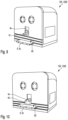
- FIG. 9 shows a schematic perspective view of the exterior of an unmanned ground-based transport vehicle according to a further embodiment of the disclosure herein;
- FIG. 10 shows a schematic perspective view of the exterior of an unmanned ground-based transport vehicle according to a further embodiment of the disclosure herein;
- FIG. 11 shows a schematic perspective view of the exterior of an unmanned ground-based transport vehicle according to a further embodiment of the disclosure herein;
- FIG. 12 shows a schematic perspective view of the exterior of an unmanned ground-based transport vehicle according to a further embodiment of the disclosure herein;
- FIG. 13 shows a schematic illustration of a load receiving situation of unmanned ground transport vehicles during the raising of a pallet
- FIG. 14 shows a schematic illustration of a load receiving situation of unmanned ground transport vehicles during the raising of a pipe
- FIG. 15 schematically illustrates a functional block diagram of a transportation system according to an embodiment of the disclosure herein.
- FIG. 16 schematically illustrates a functional block diagram of unmanned ground-based transport vehicle according to an embodiment of the disclosure herein.
- Cabin monuments within the meaning of the disclosure herein, include all installations in aircraft passenger cabins that are intended for catering for passengers and/or their use by passengers. Such installations in an aircraft passenger cabin, such as toilet assemblies, passenger seat assemblies or galleys, are also referred to as monuments, and are supplied with water, air, electricity, data or the like at the corresponding installation position via the supply lines present in the aircraft.
- the functions of the cabin monuments may be routed to the monuments via various electrical data lines and/or power supply lines.
- Unmanned transport vehicles within the meaning of the disclosure herein, in this case include driverless transport vehicles which, for the purpose of transporting goods loaded on the vehicles, perform ground-based movement operations such as, for instance, changes of direction, acceleration or braking maneuvers, substantially without human involvement or intervention, for example with the aid of sensors and software, integrated in the transport vehicle, for location, navigation, obstacle detection and path planning.
- driverless transport vehicles which, for the purpose of transporting goods loaded on the vehicles, perform ground-based movement operations such as, for instance, changes of direction, acceleration or braking maneuvers, substantially without human involvement or intervention, for example with the aid of sensors and software, integrated in the transport vehicle, for location, navigation, obstacle detection and path planning.
- FIG. 1 shows a schematic perspective view of the exterior of an unmanned ground-based transport vehicle (UGV) 100 .
- FIG. 3 shows a schematic illustration of the components present in the interior of the UGV 100 .
- FIGS. 6 to 8 show a further UGV 1000 , wherein FIGS. 6 and 7 (A)- 7 (D) show a schematic perspective view of the exterior of the UGV 1000 and FIG. 8 shows a schematic illustration of the components present in the interior of the UGV 1000 .
- FIG. 16 shows a functional block diagram of an UGV 100 , 1000 .
- an UGV 100 , 1000 may comprise a housing 1 , 1001 , at least one wheel drive 10 , at least one wheel 13 , a controller 15 , and a plurality of sensors S.
- an electrical energy storage device 16 and an UGV charging interface 120 may be provided, too.
- the UGV 100 , 1000 comprises at least on load-receiving or load-bearing element 6 which is configured to support an item to be transported and which is coupled to the housing 1 , 1001 of the UGV 100 , 1000 .
- the load-receiving element 6 may be detachably coupled to the housing, for example, such that it is stationary relative to the housing 1 , 1001 in the coupled state.
- the wheel drive 10 is kinematically coupled to the at least one wheel 13 , 130 and configured to drive the wheel 13 , 130 in order to move the UGV 100 , 1000 on a transport surface. Further, the wheel drive 10 may be configured to deflect the at least one wheel 13 , 130 so that the housing 1 , 1001 can be lifted together with the load-bearing element 6 in order to lift an item supported by the load-receiving element 6 .
- the wheel drive 10 may include at least one wheel suspension 14 and at least one lifting motor 11 .
- each wheel 13 , 130 may be coupled to an individual wheel suspension and one or more lifting motors 11 may be provided per wheel 13 , 130 .
- Operation of the wheel drive 10 may be controlled by controller 15 , for example, based on sensor data captured by sensors S.
- the controller 15 , the lifting motors 11 , and, as far as necessary, the sensors S may be supplied with electrical energy from the electrical energy storage device 16 , which may, for example, be a battery, an accumulator, or similar.
- the electrical energy storage device 16 may be charged via the UGV charging interface 120 .
- the controller 15 may comprise, for example, an ASIC, an FPGA or any other suitable computing device(s) or processor.
- the controller 15 serves to control and monitor the wheel drive, sensors and other electronic or electrical components of the UGV 100 .
- the sensors S may, for example, include a pyroelectric sensor 3 that provides information about nearby heat sources and that can thus be used to protect human workers in the vicinity of the UGV.
- Other sensors in particular environmental sensors for capturing information about the surrounding of the UGV, such as, for instance, radar sensors, ultrasonic sensors, optical sensors, IR sensors, laser sensors, lidar sensors or other types of sensors may be provided at different positions and in different arrangements on the UGV 100 , 1000 .
- sensors 2 a and 2 b are shown in FIG. 16 .
- an inclination sensor 8 may be provided.
- the sensors for environment sensing advantageously may also be used for navigation purposes.
- the controller 15 may receive the sensor data from the environment sensors and control operation of the wheel drive based on the captured sensor data.
- the environment sensors may capture an assembly progress of a product in an assembly line.
- the sensors may capture information representing an assembly state of a product to be assembled.
- bar codes attached to the already assembled items may be read by the sensors and/or an image recognition algorithm may determine from captured images which items of the product are already assembled.
- the UGV 100 may transmit the captured or determined assembly progress to a central control system, e.g. a server (not shown), and receive from the central control system a notification which item is to be transported next.
- a sensor module (not shown) may be transported on the load receiving element 6 as an item, the sensor module being equipped with a sensor system configured to capture the assembly progress and/or configured to capture quality indicators of the product.
- An UGV 100 , 1000 may be used alone or in combination with at least one further UGV 100 , 1000 for performing transportation tasks. Since each UGV 100 , 1000 comprises sensors S, each UGV 100 , 1000 may navigate autonomously. When used in combination with other UGVs 100 , 1000 , each UGV 100 , 1000 may be equipped with an individual load-receiving element 6 in order to easily couple with an interface of the item to be transported. Of course, all UGVs 100 , 1000 may also be equipped with the same type of load-receiving element 6 .
- sensor information captured by the UGVs 100 , 1000 may be shared between UGVs 100 , 1000 which together transport an item, for example, via a wireless communication module 15 A of the controller 15 . This helps the UGVs 100 , 1000 in autonomous navigation, in particular, when large items are transported and when the environment sensors of one or more of the UGVs 100 , 1000 are at least partially shadowed by the item.
- the UGV 100 , 1000 may be used for transport tasks in assembly lines, in particular, in a final assembly line of aircrafts. Due to its outstanding maneuverability, for example, because of employing omnidirectional wheels 13 , 130 , the UGV 100 , 1000 can easily navigate within the fuselage of an aircraft which is assembled. Similar, the UGV 100 , 1000 may be used in the assembly of other large products, such as ships, trains, or general in material supply of production lines. Further use cases may be loading and unloading of vehicles. Of course, other use cases of the UGV 100 , 1000 are possible, too. For example, the UGV 100 , 1000 may perform transportation tasks in indoor environments, such as in warehouses, supermarkets, offices, laboratories, hospitals, and so on, or in outdoor environments, such as airports, train stations, harbours, mines, and so on.
- the UGV 100 comprises a housing 1 , having a base plate 1 c , and at least one housing side wall 1 a that is substantially perpendicular to the base plate 1 c .
- the housing 1 may have, for example, a substantially box-shaped structure, possibly having rounded corners, on the other side faces, i.e. on the side walls that complete the housing 1 to form a closed enclosure for the internal components.
- a wheel 13 Arranged in the recess 1 d in the floor plate 1 c there is a wheel 13 , which is suspended inside the UGV 100 , for example by a wheel suspension 14 having two suspension arms 14 A, 14 B.
- the wheel 13 may be, for example, an omnidirectional wheel such as, for instance, a so-called Mecanum or lion wheel, which has a number of barrel-shaped rollers mounted rotatably on the circumference of the wheel 13 at an angle of inclination in relation to the main axis of rotation of the wheel 13 .
- the rollers provide contact with the ground or transport surface.
- the rollers can rotate freely about the inclined bearing axis.
- the wheel 13 as such is driven via a wheel drive 10 inside housing 1 with variable direction of rotation and variable rotational speed. Depending on the selected direction of rotation and rotational speed, the omnidirectional wheel 13 can move in all directions, parallel to the plane of the floor.
- the wheel 13 may be realized as an individually steered wheel having a controllable rotary suspension for rotating the wheel running axle perpendicular to the ground.
- the wheel 13 may be integrated as a drive wheel into a travel/turn module which, in addition to the rotary movement of the drive wheel, also permits an additionally active vertical axis rotation capability and alignment.
- the wheel drive in this case may have two separate drive motors, one of which drives the drive wheel of the travel/turn module, while the other effects its alignment about the vertical axis.
- the capability to rotate about the wheel running axle and the vertical axis is endless in each case, and thus enables continuous movement of the wheels without end positions.
- the wheel 13 may also be realized as an all-side wheel, i.e. as a wheel attached to the main circumferential surface of which are a number of auxiliary wheels, the axes of rotation of which are at right angles to the main axis of rotation of wheel 13 .
- the UGV 100 may comprise a plurality of sensors for environment sensing.
- pyroelectric sensor 3 attached to the top of the housing 1 there may be pyroelectric sensor 3 that provides information about nearby heat sources and that can thus be used to protect human workers in the vicinity of the UGV.
- Other sensors such as, for instance, radar sensors, ultrasonic sensors, optical sensors, IR sensors, laser sensors, lidar sensors or other types of sensors may be integrated into the housing 1 of the UGV 100 at different positions and in different arrangements.
- sensors 2 a and 2 b are represented, as examples, on different side walls of the UGV 100 in FIGS. 1 through 4 (B).
- the UGV 100 may comprise a controller 15 for autonomous location and navigation of the UGV 100 on the basis of sensing parameters of the plurality of sensors.
- the controller 15 may comprise, for example, an ASIC, an FPGA or any other suitable computing device(s) or processor.
- the controller 15 serves to control and monitor the wheel drive, sensors and other electronic or electrical components of the UGV 100 .
- FIG. 1 shows two load-receiving elements 6 a , 6 b , each representing outwardly projecting load-receiving forks 6 a and 6 b .
- FIG. 2 only one load-receiving element 6 is shown, as a widened load-receiving platform or plate 6 c .
- the load receiving elements 6 a , 6 b , 6 c each comprise a substantially even support surface 60 in order to support an item with respect to a vertical direction extending perpendicular to the base plate 1 c .
- FIG. 12 shows for example a load-receiving element 6 in the form of a substantially wedge shaped component 6 d protruding outwardly from the housing side wall 1 a .
- the wedge shaped component 6 d may comprise a concave curved support surface 60 which extends outwardly from and inclined relative to the housing side wall 1 a .
- the support surface 60 of the wedge shaped component 6 d is configured to support an item with respect to the vertical direction.
- a counterpart 61 may be coupled to the housing side wall 1 a , 1001 a in addition to the wedge shaped component 6 d .
- the counterpart 61 may extend in the vertical direction along the housing side wall 1 a , 1001 a and include a concave curved end section arranged opposite to the support surface 60 .
- Such a configuration may be advantageously used for lifting and transporting of a pipe P as is shown for example in FIG. 14 .
- the at least one load-receiving element 6 of the UGV 1 , 1001 may comprise a load support surface 60 for supporting an item with respect to a vertical direction which extends transverse to the base plate 1 c , 1001 c.
- the load-receiving elements 6 a , 6 b , 6 c may have anti-slip features provided at the load receiving surface 60 , e.g. an anti-slip material 62 ( FIG. 12 ) and/or fluted profiles ( FIGS. 1 and 2 ). It may also be possible to tilt or incline the load-receiving elements 6 relative to the horizontal, in order to compensate height differences between the load support of different UGVs.
- the grooves 5 may be, for example, T-profile or dovetail grooves, in which T-profile or dovetail tongue rails of the respective load-receiving elements 6 a , 6 b , 6 c can engage in a form-fitting manner.
- the tongue rails can be pushed into the grooves 5 from the outside.
- the grooves 5 may run parallel to the base plate 1 c and at different distances from the base plate 1 c , parallel to each other, to enable different load bearing heights to be flexibly adapted to the cargo to be transported.
- the at least one load-receiving element 6 is detachably coupled to the housing side wall 1 a .
- the at least one load receiving element 6 may be coupled to the housing side wall 1 a so as to be stationary relative to the base plate 1 c , at least with respect to the vertical direction.
- a tool carrier 4 a may also be arranged in the housing side wall 1 a .
- the tool carrier 4 a may have an electrical tool connection, i.e. for the purpose of supplying electrical power, the connection may be connected, via electrical lines, to an electrical energy storage device 16 such as, for instance, a battery or accumulator, inside housing 1 .
- the electrical energy storage device 16 may also provide an independent power supply for the other electrical and electronic components of the UGV 100 .
- the tool carrier 4 a may be movable in the vertical direction relative to the base plate 1 c , e.g. by a carrier lift motor (not shown) kinematically coupled to the tool carrier 4 a.
- FIG. 2 illustrates an electrically operated suction pad 4 b , which is connected to the electrical tool connection.
- the suction pad 4 b may be, for example, a vacuum suction pad that rests against a flat outer surface of the cargo to be transported and that enables improved handling of the cargo by a vacuum between the suction surface and the outer surface.
- FIG. 9 shows for example a horizontal stop 4 c coupled to the tool carrier 4 a , which may be pivotal about an axis extending in the vertical direction.
- the stop 4 c may be used to support an item to be transported with respect to direction parallel to the base plate 1 c , 1001 c .
- FIG. 10 shows a vertical stop or clamp element 4 d coupled to the tool carrier 4 a .
- the clamp element 4 d may serve for clamping an item between the clamp element 4 d and the support surface 60 of the load-receiving element 6 .
- FIG. 11 shows for example a magnet interface 4 e coupled to the housing side wall 1 a , 1001 a .
- the magnet interface 4 e may include a carrier plate 40 mechanically coupled to the side wall 1 a , 1000 a and a magnet device 41 , in particular an electromagnet, coupled to the tool carrier 4 a .
- the carrier plate 40 may be detachably coupled to the side wall 1 a , 10001 , for example, by the T-profile or dovetail groove 5 in the same fashion as described above for the load-receiving element 6 .
- the magnet device 41 may be mechanically and/or electrically coupled to the tool carrier 4 a .
- the magnet device 41 can be activated, e.g. supplied with electrical energy by the tool carrier 4 a , and, optionally, be moved relative to the carrier plate 40 , in particular in the vertical direction, by the tool carrier 4 a .
- FIG. 12 shows the counterpart 62 to be coupled to the tool carrier 4 a .
- tools may include manipulators, for example, manipulator arms which enable manipulation of the items, for example, gripping and rotating of the items.
- two lifting motors 11 may be provided inside housing 1 , to enable the cargo or item to be raised after the cargo has been loaded onto the load-receiving elements 6 .
- These lifting motors 11 are configured to deflect the wheel suspension arms 14 A, 14 B, relative to the housing 1 , in a direction perpendicular to the base plate 1 c , that is, in the vertical direction.
- the wheel suspension arms 14 A, 14 B may be connected to the housing 1 via two sawtooth-threaded rods 12 coupled to the two lifting motors 11 , such that the lifting motors 11 can shift the wheel suspension arms 14 up or down along the course of the sawtooth-threaded rods 12 , and thus retract or extend the omnidirectional wheel 13 from the recess 1 c .
- the lifting motors 11 may be electric motors such as, for example, stepper motors or servo motors.
- the UGV 100 shown for example in FIGS. 1 through 4 (B) comprises exactly one wheel 13 .
- One wheel drive 10 is provided for this wheel 13 , including one wheel suspension 14 and two lifting motors 11 .
- the wheel drive 10 may comprise at least one wheel suspension 14 per wheel and at least one lifting motor 11 per wheel, wherein each lifting motor 11 is kinematically coupled to one wheel so as to deflect the wheel relative to the housing in the vertical direction.
- the wheel suspension 14 is moved downwards along the sawtooth-threaded rods 12 by rotational movement, such that the omnidirectional wheel 13 moves out of the recess 1 d , downwards out of housing 1 , and thus the entire housing 1 is raised from the floor until the full lifting height is attained, in FIG. 4 (B) .
- the controller 15 of the UGV 100 may include a wireless communication module 15 A ( FIG. 16 ), via which the controller 15 of a first UGV 100 can exchange data with a controller 15 of a second UGV 100 .
- different UGVs 100 may each be designated as a lead vehicle (“master”) or follower vehicle (“slaves”), such that the controller 15 of the lead vehicle is connected to the controller 15 of the follower vehicles via wireless communication, and can control and monitor the movements of the follower vehicles.
- sensor data captured by the sensors S may be shared between the UGVs 100 via the wireless communication module 15 A.
- UGVs 100 e.g. UGVs 100 as represented and explained in FIGS. 1 through 4 (B)—are distributed around the outer circumference of a cabin monument.
- UGVs 100 e.g. UGVs 100 as represented and explained in FIGS. 1 through 4 (B)—are distributed around the outer circumference of a cabin monument.
- four UGVs, each having one wheel, are arranged in a specially arranged constellation in relation to the payload.
- the cabin monument is placed in a suitable manner on the load-receiving elements of the UGVs 100 , such that the cabin monument can be raised in a coordinated movement by the lifting motors 11 of the UGVs 100 .
- the cabin monument, raised thus, can then be moved by cooperative control of the omnidirectional wheels 13 of the at least three UGVs 100 , for example within a final assembly line, from a delivery point to a final assembly position.
- one of the at least three UGV 100 s may assume the role of lead vehicle.
- the controller 15 of the lead vehicle communicates, via wireless communication, with the controller 15 of the other UGVs 100 , and can issue movement commands to the follower vehicles.
- FIG. 5 (A)- 5 (C) are schematic illustrations of three load receiving situations of UGVs 100 during the raising of cabin monuments.
- a UGV 100 may raise a passenger seat assembly 20 .
- support wedges 7 a and 7 b each having anti-slip materials on its sloping surfaces, may be placed on the load-receiving elements, or on the load-receiving element of the UGV 100 .
- the UGV 100 can thus also receive sloping undersides such as, for instance, cross-members 21 of a passenger seat assembly 20 , in a straight line and without tipping.
- FIG. 5 (B) another UGV 100 receives the passenger seat assembly 20 on a load-receiving platform 6 c . No further support wedges are necessary here, since the underside of the passenger seat assembly 20 has a straight mounting bar 22 at this point.
- the tool connection of the tool carrier 4 a of a UGV 100 may be used—as shown as an example in FIG. 5 (C) —to engage in connection interfaces 32 in a side wall 31 of a toilet assembly 30 having a toilet door 33 , and to supply it with electrical supply signals.
- This allows, for example, the functionality of the assembly to be controlled during transport and checked if necessary.
- FIG. 13 shows for example a palette C being lifted and transported by four UGVs 100 , 1000 (only three visible in FIG. 13 ).
- items may be loaded, such as doors for vehicles, as shown for example in FIG. 13 .
- FIG. 14 shows for example using the above described method for lifting and transporting a pipe P by four UGVs 100 , 1000 (only three visible in FIG. 14 ).
- FIGS. 6 through 8 show an embodiment 1000 of a UGV that has an arrangement of four wheels 130 .
- the mobility of the UGV 1000 in all directions results from the fact that a UGV 1000 has four specially arranged Mecanum wheels. It may also be possible to provide the UGV with individually steered wheels having a controllable rotary suspension for rotating the wheel running axle perpendicular to the ground.
- the UGV 100 may comprise four omnidirectional wheels.
- the essential elements and the mode of operation of the UGV 1000 are essentially the same as those of the UGV 100 described in connection with FIGS.
- a housing 1001 having a base plate 1001 c and at least one housing side wall 1001 a substantially perpendicular to the base plate 1001 c , being likewise provided.
- the housing 1000 On the rest of the side surfaces, i.e. on the side walls that complete the housing 1000 to form a closed enclosure for the internal components, the housing 1000 may have, for example, a substantially box-shaped structure, possibly having rounded corners.
- the recess or recesses 1001 d of the base plate 1001 c are four wheels 130 , which are suspended by wheel suspensions 14 inside the UGV.
- Such a design is advantageous, for example, if the load of the item to be transported is transferred to the transport surface not only via one wheel of the UGV, but via a plurality of wheels, and thus a plurality of load application points.
- This can be advantageous, in particular, if the transport surface is also the floor plate of an aircraft, and this surface should not be subjected to excessive loads.
- FIGS. 7 (A)- 7 (D) it is shown that the wheels 130 can be lowered or retracted by lifting motors. It is possible in this case to arrange them on two axles, but the wheels may also be controlled, or raised and lowered, individually, for example by aid of the wheel suspension 14 provided for each wheel.
- FIGS. 7 (A)- 7 (D) show various operating states. Thus, FIG. 7 (A) shows retracted wheels 130 , FIG. 7 (B) shows the wheels 130 extended, and FIGS. 7 (C) and 7 (D) show either the front or the rear wheels 130 retracted when, at the same time, the wheels 130 on the other axle are extended.
- the UGV 1000 may comprise an inclination sensor 8 configured to capture an inclination of the base plate 1001 c relative to a predefined reference direction, i.e. the direction of gravity.
- the inclination sensor 8 may include three electronic acceleration sensors which measure an acceleration along three perpendicular axes.
- the controller 15 of the UGV 1000 receives the measured or captured inclination of the base plate 1001 c and controls the lifting motors 11 coupled to the wheels 130 such that of the base plate 1001 a relative to the reference direction is kept within a predefined range.
- the UGVs 1000 may communicate the inclination of their base plates to each other and further a lifting value of each of their wheels 130 , wherein the controller 15 of the lead UGV is configured to issue control commands to each UGV 1000 of the swarm of UGVs 1000 for controlling the lifting motors 11 of each UGV 1000 such that an inclination of the item relative to the reference direction, which results from its contact with the load-receiving elements 6 of the UGVs 1000 , is kept within a predefined range.
- FIG. 8 shows a detailed view of the interior of the UGV 1000 .
- the drive mechanism or wheel drive 10 and the lifting and lowering mechanism or wheel suspensions are arranged in a compact design. Also provided are energy storage devices, which enable the UGV 1000 to move independently.
- UGVs 1000 can be transported by a method using a cooperatively acting swarm of UGVs. This method can be carried out by all types of UGVs 100 , 1000 described above, irrespective of the number of wheels 13 , 130 .
- UGVs 1000 having more than one wheel 130 are used, at least two UGVs 1000 —e.g. UGVs 100 as represented and explained in FIGS. 6 to 8 or 9 to 12 —are distributed around the outer circumference of an item, for example a cabin monument.
- the item is placed in a suitable manner on the load-receiving elements 6 of the UGVs 1000 , such that the cabin monument can be raised in a coordinated movement by the lifting motors 11 of the UGVs 1000 .
- the wheels 13 are deflected relative to the base plate 1001 c in the vertical direction.
- the item, raised thus, can then be moved by cooperative control of the omnidirectional wheels 130 of the at least two UGVs 1000 , for example within a final assembly line, from a delivery point to a final assembly position.
- a method as described above, for example, may be carried out by an unmanned transport system, UTS, 200 including two or more UGVs 100 , 1000 .
- FIG. 15 schematically shows an UTS 200 comprising four UGVs 100 , 1000 and a base station 210 .
- the UGVs 100 , 1000 may be configured as described above.
- the base station 210 may comprise an electrical current supply 230 , at least one electrical charging interface 220 for charging the UGVs 100 , 1000 , and an optional tool changer 240 .
- the charging interfaces 230 may comprise a charging plate 221 , onto which the UGV 100 , 1000 can drive and park, and a charging inductor coil 222 arranged beneath the charging plate 221 or integrated into the charging plate 221 .
- the charging interfaces 220 are electrically connected to the current supply 230 of the base station 210 .
- a controller (not shown) may be provided for controlling operation of the charging interfaces 230 .
- the UGV 100 , 1000 may comprise an UGV charging interface 120 which is only schematically shown in FIG. 16 .
- the UGV charging interface 120 is configured for being connected to the charging interfaces 230 of the base station 220 .
- the UGV charging interface 120 is configured for being autonomously connected to the charging interfaces 230 of the base station 220 .
- the UGV charging interface 120 may comprise a receiving inductor coil (not shown) arranged on or integrated into the base plate 1 c , 1001 d of the housing the UGV charging interface 120 .
- the UGV may simply drive onto the charging plate of the base station. Thus, charging can be performed autonomously in a very simple manner.
- the optional tool changer 220 may include a magazine holding various tools, for example, suction pads 4 b ( FIG. 2 ), stop elements 4 c ( FIG. 9 ), clamp elements 4 d ( FIG. 10 ), magnet interfaces 4 e ( FIG. 11 ), counterparts 62 ( FIG. 12 ), and so on.
- An UGV 100 , 1000 of the transport system 200 may autonomously drive to the tool changer 220 and couple the respective tool to its tool carrier.
Landscapes
- Engineering & Computer Science (AREA)
- Transportation (AREA)
- Structural Engineering (AREA)
- Mechanical Engineering (AREA)
- Geology (AREA)
- Life Sciences & Earth Sciences (AREA)
- Civil Engineering (AREA)
- Automation & Control Theory (AREA)
- Aviation & Aerospace Engineering (AREA)
- Remote Sensing (AREA)
- Radar, Positioning & Navigation (AREA)
- General Physics & Mathematics (AREA)
- Physics & Mathematics (AREA)
- Combustion & Propulsion (AREA)
- Chemical & Material Sciences (AREA)
- Human Computer Interaction (AREA)
- Manufacturing & Machinery (AREA)
- Health & Medical Sciences (AREA)
- Public Health (AREA)
- Power Engineering (AREA)
- Handcart (AREA)
- Control Of Position, Course, Altitude, Or Attitude Of Moving Bodies (AREA)
- Manipulator (AREA)
- Electric Propulsion And Braking For Vehicles (AREA)
Abstract
Description
Claims (18)
Applications Claiming Priority (5)
| Application Number | Priority Date | Filing Date | Title |
|---|---|---|---|
| DE102019202558.7A DE102019202558A1 (en) | 2019-02-26 | 2019-02-26 | UNMANNED GROUND TRANSPORT VEHICLE AND METHOD OF TRANSPORTING CABIN MONUMENTS |
| DE102019202558.7 | 2019-02-26 | ||
| DE102019124706.3 | 2019-09-13 | ||
| DE102019124706 | 2019-09-13 | ||
| PCT/EP2020/054990 WO2020173982A1 (en) | 2019-02-26 | 2020-02-26 | Unmanned ground-based transport vehicle and method for transporting items |
Related Parent Applications (1)
| Application Number | Title | Priority Date | Filing Date |
|---|---|---|---|
| PCT/EP2020/054990 Continuation WO2020173982A1 (en) | 2019-02-26 | 2020-02-26 | Unmanned ground-based transport vehicle and method for transporting items |
Publications (2)
| Publication Number | Publication Date |
|---|---|
| US20220024738A1 US20220024738A1 (en) | 2022-01-27 |
| US12269720B2 true US12269720B2 (en) | 2025-04-08 |
Family
ID=69780148
Family Applications (1)
| Application Number | Title | Priority Date | Filing Date |
|---|---|---|---|
| US17/412,983 Active 2041-11-18 US12269720B2 (en) | 2019-02-26 | 2021-08-26 | Unmanned ground-based transport vehicle and method for transporting items |
Country Status (7)
| Country | Link |
|---|---|
| US (1) | US12269720B2 (en) |
| EP (2) | EP3931656B1 (en) |
| JP (1) | JP7502318B2 (en) |
| KR (1) | KR102889717B1 (en) |
| CN (1) | CN113692559A (en) |
| ES (2) | ES3060252T3 (en) |
| WO (1) | WO2020173982A1 (en) |
Families Citing this family (13)
| Publication number | Priority date | Publication date | Assignee | Title |
|---|---|---|---|---|
| JP7502318B2 (en) | 2019-02-26 | 2024-06-18 | エアバス オペレーションズ ゲーエムベーハー | Unmanned ground transport vehicle, unmanned transport system, and method for transporting goods |
| US11676492B2 (en) * | 2019-08-30 | 2023-06-13 | Kabushiki Kaisha Toshiba | System and method for cooperative robotics |
| DE102020209746A1 (en) | 2020-07-31 | 2022-02-03 | Airbus Operations Gmbh | UNMANNED GROUND VEHICLE FOR HYGIENE MAINTENANCE AND METHODS FOR IMPROVING SANITARY CONDITIONS |
| US12110050B2 (en) | 2021-12-14 | 2024-10-08 | Fq Ip Ab | Navigator |
| EP4015357A1 (en) | 2020-12-15 | 2022-06-22 | Fq Ip Ab | Navigator |
| CN113306475A (en) * | 2021-07-16 | 2021-08-27 | 北京京东乾石科技有限公司 | Chassis assembly and automated guided vehicle |
| US20240308824A1 (en) * | 2022-02-04 | 2024-09-19 | Fq Ip Ab | Navigator interface |
| CA3243258A1 (en) * | 2022-02-04 | 2023-08-10 | Fq Ip Ab | Self propelled adaptor unit and system for intralogistics comprising an adaptor |
| NO347926B1 (en) * | 2022-08-24 | 2024-05-13 | Wheel Me As | System for mounting and releasing a wheel to and from a wheel support |
| KR102608350B1 (en) * | 2023-04-27 | 2023-12-01 | (주)시스콘 | Concurrent control method and system for automated guided vehicle |
| EP4563517A1 (en) * | 2023-12-01 | 2025-06-04 | Mobile Industrial Robots A/S | Mobile robot braking |
| US12275606B1 (en) | 2023-12-27 | 2025-04-15 | Niagara Bottling, Llc | Facility layout |
| US12265400B1 (en) | 2023-12-27 | 2025-04-01 | Niagara Bottling, Llc | Facility layout |
Citations (25)
| Publication number | Priority date | Publication date | Assignee | Title |
|---|---|---|---|---|
| US6104314A (en) | 1998-02-10 | 2000-08-15 | Jiang; Jung-Jye | Automatic parking apparatus |
| JP2007111826A (en) | 2005-10-20 | 2007-05-10 | Ishikawajima Harima Heavy Ind Co Ltd | Coordinated transport system and method using a plurality of robots having a gripping mechanism with backlash and sliding |
| US20100030382A1 (en) | 2008-07-31 | 2010-02-04 | University Of Medicine And Dentistry Of New Jersey | Inhalable particulate environmental robotic sampler |
| US20100300837A1 (en) | 2007-10-29 | 2010-12-02 | Ihi Transport Machinery Co., Ltd. | Object moving apparatus |
| US20120039693A1 (en) * | 2010-08-12 | 2012-02-16 | Benedict Charles E | Automated Automotive Vehicle Parking /Storage System |
| WO2014007729A1 (en) | 2012-07-05 | 2014-01-09 | Husqvarna Ab | Modular robotic vehicle |
| US20140172223A1 (en) | 2012-12-18 | 2014-06-19 | Christopher John Murphy | Method of material handling with automatic guided vehicles |
| US20140365258A1 (en) | 2012-02-08 | 2014-12-11 | Adept Technology, Inc. | Job management system for a fleet of autonomous mobile robots |
| DE102013016381A1 (en) | 2013-09-30 | 2015-04-02 | Grenzebach Maschinenbau Gmbh | Transport vehicle and method for the trouble-free transport of load racks in factory halls with radio shading and with partially autonomous driving operation |
| US9149549B2 (en) | 2013-02-27 | 2015-10-06 | Arthur Kreitenberg | Sanitizing surfaces associated with assembly areas |
| DE10196992B4 (en) | 2000-12-04 | 2016-09-15 | Robcab Ab | robot system |
| US20160368149A1 (en) | 2015-06-22 | 2016-12-22 | Daiki INABA | Robot, information processing system, and storage medium |
| US20170072565A1 (en) * | 2014-05-05 | 2017-03-16 | Georgia Tech Research Corporation | Control of Swarming Robots |
| US20170308084A1 (en) | 2016-04-20 | 2017-10-26 | GM Global Technology Operations LLC | Reconfigurable automated guided vehicle system |
| EP3094796B1 (en) | 2014-08-27 | 2018-04-25 | Nussbaum Technologies GmbH | Automated parking system for vehicles |
| CN108946586A (en) | 2018-09-14 | 2018-12-07 | 浙江斐尔德智能设备有限公司 | Mobyneb automated guided vehicle |
| US20190001824A1 (en) * | 2017-06-30 | 2019-01-03 | Beijing Hanergy Solar Power Investment Co., Ltd. | Solar support mounted on a vehicle roof |
| US20190242916A1 (en) | 2018-02-02 | 2019-08-08 | HighRes Biosolutions, Inc. | Auto-navigating robotic processing vehicle |
| CA3089452A1 (en) | 2018-02-20 | 2019-08-29 | Universite De Reims Champagne-Ardenne | Robot interconnection method |
| US20190314993A1 (en) | 2018-04-13 | 2019-10-17 | The Boeing Company | Airplane Passenger Service Robot |
| CN209758195U (en) | 2019-02-01 | 2019-12-10 | 深圳市海柔创新科技有限公司 | a handling robot |
| US20200122321A1 (en) * | 2018-10-23 | 2020-04-23 | X Development Llc | Machine learning methods and apparatus for automated robotic placement of secured object in appropriate location |
| WO2020173982A1 (en) | 2019-02-26 | 2020-09-03 | Airbus Operations Gmbh | Unmanned ground-based transport vehicle and method for transporting items |
| US20210232148A1 (en) * | 2018-10-10 | 2021-07-29 | Lingdong Technology (Beijing) Co. Ltd | Human interacting automatic guided vehicle |
| US20220031895A1 (en) | 2020-07-31 | 2022-02-03 | Airbus Operations Gmbh | Unmanned ground-based hygiene maintenance vehicle and method for improving hygiene conditions |
Family Cites Families (8)
| Publication number | Priority date | Publication date | Assignee | Title |
|---|---|---|---|---|
| JPH07228498A (en) * | 1994-02-15 | 1995-08-29 | Sumitomo Heavy Ind Ltd | Fork-lift handling method for drum can and fork-lift device for drum can |
| DE4443943A1 (en) | 1994-12-09 | 1996-06-13 | Schneider Walter Gmbh Co Kg | Convertible road=rail vehicle with pneumatic tyres |
| JP2007074800A (en) | 2005-09-06 | 2007-03-22 | Tsubakimoto Chain Co | Battery charge/discharge management system of automatic carrier vehicle |
| WO2014021363A1 (en) * | 2012-08-02 | 2014-02-06 | 日産自動車株式会社 | Charging management system for unpiloted conveyance vehicle and charging management method |
| US10835948B2 (en) * | 2014-07-09 | 2020-11-17 | The Boeing Company | Adjustable retaining structure for a cradle fixture |
| DE102015101340A1 (en) * | 2015-01-29 | 2016-08-04 | Jungheinrich Aktiengesellschaft | Fork carrier for a hoist |
| CN106183671A (en) | 2016-08-16 | 2016-12-07 | 中国矿业大学 | Wheel track dual-purpose all-around mobile carrying platform |
| CN106672867A (en) | 2017-02-21 | 2017-05-17 | 上海大学 | Separated type miniature autonomous carrying goods fork capable of working cooperatively |
-
2020
- 2020-02-26 JP JP2021549912A patent/JP7502318B2/en active Active
- 2020-02-26 CN CN202080016424.0A patent/CN113692559A/en active Pending
- 2020-02-26 EP EP20710066.0A patent/EP3931656B1/en active Active
- 2020-02-26 WO PCT/EP2020/054990 patent/WO2020173982A1/en not_active Ceased
- 2020-02-26 KR KR1020217027389A patent/KR102889717B1/en active Active
- 2020-02-26 ES ES23154471T patent/ES3060252T3/en active Active
- 2020-02-26 EP EP23154471.9A patent/EP4194990B1/en active Active
- 2020-02-26 ES ES20710066T patent/ES2941784T3/en active Active
-
2021
- 2021-08-26 US US17/412,983 patent/US12269720B2/en active Active
Patent Citations (25)
| Publication number | Priority date | Publication date | Assignee | Title |
|---|---|---|---|---|
| US6104314A (en) | 1998-02-10 | 2000-08-15 | Jiang; Jung-Jye | Automatic parking apparatus |
| DE10196992B4 (en) | 2000-12-04 | 2016-09-15 | Robcab Ab | robot system |
| JP2007111826A (en) | 2005-10-20 | 2007-05-10 | Ishikawajima Harima Heavy Ind Co Ltd | Coordinated transport system and method using a plurality of robots having a gripping mechanism with backlash and sliding |
| US20100300837A1 (en) | 2007-10-29 | 2010-12-02 | Ihi Transport Machinery Co., Ltd. | Object moving apparatus |
| US20100030382A1 (en) | 2008-07-31 | 2010-02-04 | University Of Medicine And Dentistry Of New Jersey | Inhalable particulate environmental robotic sampler |
| US20120039693A1 (en) * | 2010-08-12 | 2012-02-16 | Benedict Charles E | Automated Automotive Vehicle Parking /Storage System |
| US20140365258A1 (en) | 2012-02-08 | 2014-12-11 | Adept Technology, Inc. | Job management system for a fleet of autonomous mobile robots |
| WO2014007729A1 (en) | 2012-07-05 | 2014-01-09 | Husqvarna Ab | Modular robotic vehicle |
| US20140172223A1 (en) | 2012-12-18 | 2014-06-19 | Christopher John Murphy | Method of material handling with automatic guided vehicles |
| US9149549B2 (en) | 2013-02-27 | 2015-10-06 | Arthur Kreitenberg | Sanitizing surfaces associated with assembly areas |
| DE102013016381A1 (en) | 2013-09-30 | 2015-04-02 | Grenzebach Maschinenbau Gmbh | Transport vehicle and method for the trouble-free transport of load racks in factory halls with radio shading and with partially autonomous driving operation |
| US20170072565A1 (en) * | 2014-05-05 | 2017-03-16 | Georgia Tech Research Corporation | Control of Swarming Robots |
| EP3094796B1 (en) | 2014-08-27 | 2018-04-25 | Nussbaum Technologies GmbH | Automated parking system for vehicles |
| US20160368149A1 (en) | 2015-06-22 | 2016-12-22 | Daiki INABA | Robot, information processing system, and storage medium |
| US20170308084A1 (en) | 2016-04-20 | 2017-10-26 | GM Global Technology Operations LLC | Reconfigurable automated guided vehicle system |
| US20190001824A1 (en) * | 2017-06-30 | 2019-01-03 | Beijing Hanergy Solar Power Investment Co., Ltd. | Solar support mounted on a vehicle roof |
| US20190242916A1 (en) | 2018-02-02 | 2019-08-08 | HighRes Biosolutions, Inc. | Auto-navigating robotic processing vehicle |
| CA3089452A1 (en) | 2018-02-20 | 2019-08-29 | Universite De Reims Champagne-Ardenne | Robot interconnection method |
| US20190314993A1 (en) | 2018-04-13 | 2019-10-17 | The Boeing Company | Airplane Passenger Service Robot |
| CN108946586A (en) | 2018-09-14 | 2018-12-07 | 浙江斐尔德智能设备有限公司 | Mobyneb automated guided vehicle |
| US20210232148A1 (en) * | 2018-10-10 | 2021-07-29 | Lingdong Technology (Beijing) Co. Ltd | Human interacting automatic guided vehicle |
| US20200122321A1 (en) * | 2018-10-23 | 2020-04-23 | X Development Llc | Machine learning methods and apparatus for automated robotic placement of secured object in appropriate location |
| CN209758195U (en) | 2019-02-01 | 2019-12-10 | 深圳市海柔创新科技有限公司 | a handling robot |
| WO2020173982A1 (en) | 2019-02-26 | 2020-09-03 | Airbus Operations Gmbh | Unmanned ground-based transport vehicle and method for transporting items |
| US20220031895A1 (en) | 2020-07-31 | 2022-02-03 | Airbus Operations Gmbh | Unmanned ground-based hygiene maintenance vehicle and method for improving hygiene conditions |
Non-Patent Citations (7)
| Title |
|---|
| European Office Action for Application No. 2186293 dated Dec. 20, 2021. |
| European Office Action in EP Application No. 23154471.9, dated Sep. 16, 2024, 3 pages. |
| European Search Report for Application No. 23154479 dated Mar. 3, 2023. |
| German Search Report for Application No. 102019202558 dated Dec. 4, 2019. |
| International Search Report and Written Opinion for Application No. PCT/EP2020/054990 dated Jul. 7, 2020. |
| Machine Translation of Japanese Office Action for Application No. 2021549912 dated Sep. 26, 2023. |
| WLUK-TV Fox 11, GDW7TUE Police Car Computers SOT, May 14, 2013, YouTube, https://www.youtube.com/watch?v=6SrPriJBOYs (Year: 2013). * |
Also Published As
| Publication number | Publication date |
|---|---|
| EP3931656A1 (en) | 2022-01-05 |
| ES2941784T3 (en) | 2023-05-25 |
| ES3060252T3 (en) | 2026-03-25 |
| JP7502318B2 (en) | 2024-06-18 |
| EP3931656B1 (en) | 2023-02-22 |
| EP4194990A1 (en) | 2023-06-14 |
| US20220024738A1 (en) | 2022-01-27 |
| CN113692559A (en) | 2021-11-23 |
| EP4194990B1 (en) | 2025-11-05 |
| KR102889717B1 (en) | 2025-12-01 |
| KR20210145131A (en) | 2021-12-01 |
| WO2020173982A1 (en) | 2020-09-03 |
| JP2022523523A (en) | 2022-04-25 |
Similar Documents
| Publication | Publication Date | Title |
|---|---|---|
| US12269720B2 (en) | Unmanned ground-based transport vehicle and method for transporting items | |
| US12544470B2 (en) | Unmanned ground-based hygiene maintenance vehicle and method for improving hygiene conditions | |
| US11383383B2 (en) | Vehicle transport apparatus | |
| JP7364763B2 (en) | Vehicle transport system | |
| KR101738134B1 (en) | Apparatus for conveying product and method thereof | |
| CN112977670A (en) | Omnidirectional trolley conveying mechanism | |
| US20140309809A1 (en) | Self-propelled robotic pallet vehicle | |
| US11458631B2 (en) | Vehicle transport apparatus | |
| US11511981B2 (en) | Robotic powered cargo handling system | |
| CN114728676A (en) | Autonomous mobile system for use as reconfigurable operating system in industrial plant | |
| CN111285137A (en) | Loading system and loading method | |
| CN116745226A (en) | Transport vehicle and method for transporting load units to the vehicle | |
| CN116601072A (en) | Navigation device | |
| CN118458387A (en) | Intelligent transportation robot and transportation method | |
| WO2023205436A2 (en) | Automating delivery vehicle loading and unloading | |
| CN120397748B (en) | Box-packaged emulsion explosive unloading, stacking and carrying method and system | |
| CN223721928U (en) | Roller conveying device based on AMR car | |
| US20260048964A1 (en) | Passenger transport system and method for transporting a passenger | |
| Igarashi et al. | Development of automated transport system | |
| CN121224564A (en) | A low-speed unmanned vehicle with collaborative loading and unloading capabilities and its operating method | |
| WO2025237972A2 (en) | Transport vehicle with lift and rotate functionality | |
| WO2024219378A1 (en) | Non-contact power supply system |
Legal Events
| Date | Code | Title | Description |
|---|---|---|---|
| FEPP | Fee payment procedure |
Free format text: ENTITY STATUS SET TO UNDISCOUNTED (ORIGINAL EVENT CODE: BIG.); ENTITY STATUS OF PATENT OWNER: LARGE ENTITY |
|
| AS | Assignment |
Owner name: ALTRAN DEUTSCHLAND S.A.S. & CO. KG, GERMANY Free format text: ASSIGNMENT OF ASSIGNORS INTEREST;ASSIGNORS:LE POLOTEC, CHRISTIAN;STOPP, THOMAS;KOSSOW, MATTHIAS;SIGNING DATES FROM 20210813 TO 20210830;REEL/FRAME:057698/0278 Owner name: AIRBUS OPERATIONS GMBH, GERMANY Free format text: ASSIGNMENT OF ASSIGNORS INTEREST;ASSIGNORS:LE POLOTEC, CHRISTIAN;STOPP, THOMAS;KOSSOW, MATTHIAS;SIGNING DATES FROM 20210813 TO 20210830;REEL/FRAME:057698/0278 |
|
| STPP | Information on status: patent application and granting procedure in general |
Free format text: DOCKETED NEW CASE - READY FOR EXAMINATION |
|
| STPP | Information on status: patent application and granting procedure in general |
Free format text: NON FINAL ACTION MAILED |
|
| STPP | Information on status: patent application and granting procedure in general |
Free format text: RESPONSE TO NON-FINAL OFFICE ACTION ENTERED AND FORWARDED TO EXAMINER |
|
| AS | Assignment |
Owner name: CAPGEMINI ENGINEERING DEUTSCHLAND S.A.S. & CO. KG, GERMANY Free format text: CHANGE OF NAME;ASSIGNOR:ALTRAN DEUTSCHLAND S.A.S. & CO. KG;REEL/FRAME:066377/0441 Effective date: 20230720 |
|
| STPP | Information on status: patent application and granting procedure in general |
Free format text: RESPONSE TO NON-FINAL OFFICE ACTION ENTERED AND FORWARDED TO EXAMINER |
|
| STPP | Information on status: patent application and granting procedure in general |
Free format text: NON FINAL ACTION MAILED |
|
| STPP | Information on status: patent application and granting procedure in general |
Free format text: NOTICE OF ALLOWANCE MAILED -- APPLICATION RECEIVED IN OFFICE OF PUBLICATIONS |
|
| STPP | Information on status: patent application and granting procedure in general |
Free format text: AWAITING TC RESP., ISSUE FEE NOT PAID |
|
| STPP | Information on status: patent application and granting procedure in general |
Free format text: NOTICE OF ALLOWANCE MAILED -- APPLICATION RECEIVED IN OFFICE OF PUBLICATIONS |
|
| STPP | Information on status: patent application and granting procedure in general |
Free format text: PUBLICATIONS -- ISSUE FEE PAYMENT RECEIVED |
|
| STPP | Information on status: patent application and granting procedure in general |
Free format text: PUBLICATIONS -- ISSUE FEE PAYMENT VERIFIED |
|
| STCF | Information on status: patent grant |
Free format text: PATENTED CASE |