US12269385B2 - Seat back - Google Patents
Seat back Download PDFInfo
- Publication number
- US12269385B2 US12269385B2 US17/987,041 US202217987041A US12269385B2 US 12269385 B2 US12269385 B2 US 12269385B2 US 202217987041 A US202217987041 A US 202217987041A US 12269385 B2 US12269385 B2 US 12269385B2
- Authority
- US
- United States
- Prior art keywords
- board
- coupling
- frame
- coupling portion
- seat
- Prior art date
- Legal status (The legal status is an assumption and is not a legal conclusion. Google has not performed a legal analysis and makes no representation as to the accuracy of the status listed.)
- Active, expires
Links
Images


Classifications
-
- A—HUMAN NECESSITIES
- A47—FURNITURE; DOMESTIC ARTICLES OR APPLIANCES; COFFEE MILLS; SPICE MILLS; SUCTION CLEANERS IN GENERAL
- A47C—CHAIRS; SOFAS; BEDS
- A47C7/00—Parts, details, or accessories of chairs or stools
- A47C7/36—Supports for the head or the back
- A47C7/40—Supports for the head or the back for the back
- A47C7/42—Supports for the head or the back for the back of detachable or loose type
-
- B—PERFORMING OPERATIONS; TRANSPORTING
- B60—VEHICLES IN GENERAL
- B60N—SEATS SPECIALLY ADAPTED FOR VEHICLES; VEHICLE PASSENGER ACCOMMODATION NOT OTHERWISE PROVIDED FOR
- B60N2/00—Seats specially adapted for vehicles; Arrangement or mounting of seats in vehicles
- B60N2/68—Seat frames
- B60N2/682—Joining means
-
- B—PERFORMING OPERATIONS; TRANSPORTING
- B60—VEHICLES IN GENERAL
- B60N—SEATS SPECIALLY ADAPTED FOR VEHICLES; VEHICLE PASSENGER ACCOMMODATION NOT OTHERWISE PROVIDED FOR
- B60N2/00—Seats specially adapted for vehicles; Arrangement or mounting of seats in vehicles
- B60N2/90—Details or parts not otherwise provided for
-
- A—HUMAN NECESSITIES
- A47—FURNITURE; DOMESTIC ARTICLES OR APPLIANCES; COFFEE MILLS; SPICE MILLS; SUCTION CLEANERS IN GENERAL
- A47C—CHAIRS; SOFAS; BEDS
- A47C7/00—Parts, details, or accessories of chairs or stools
- A47C7/002—Chair or stool bases
-
- A—HUMAN NECESSITIES
- A47—FURNITURE; DOMESTIC ARTICLES OR APPLIANCES; COFFEE MILLS; SPICE MILLS; SUCTION CLEANERS IN GENERAL
- A47C—CHAIRS; SOFAS; BEDS
- A47C7/00—Parts, details, or accessories of chairs or stools
- A47C7/36—Supports for the head or the back
- A47C7/40—Supports for the head or the back for the back
-
- B—PERFORMING OPERATIONS; TRANSPORTING
- B60—VEHICLES IN GENERAL
- B60N—SEATS SPECIALLY ADAPTED FOR VEHICLES; VEHICLE PASSENGER ACCOMMODATION NOT OTHERWISE PROVIDED FOR
- B60N2/00—Seats specially adapted for vehicles; Arrangement or mounting of seats in vehicles
- B60N2/58—Seat coverings
- B60N2/60—Removable protective coverings
- B60N2/6009—Removable protective coverings covering more than only the seat
-
- B—PERFORMING OPERATIONS; TRANSPORTING
- B60—VEHICLES IN GENERAL
- B60N—SEATS SPECIALLY ADAPTED FOR VEHICLES; VEHICLE PASSENGER ACCOMMODATION NOT OTHERWISE PROVIDED FOR
- B60N2/00—Seats specially adapted for vehicles; Arrangement or mounting of seats in vehicles
- B60N2/68—Seat frames
- B60N2/686—Panel like structures
Definitions
- the present disclosure relates to a seat back. Specifically, the present disclosure relates to a seat back that supports a back of a seated person.
- JP-A-2002-142913 discloses a seat back including, on a back thereof, a back board serving as a decorative plate.
- the above-described seat back includes a pair of upper and lower auxiliary frames that are provided on side frames of a back frame forming an internal skeleton across a seat width direction.
- the back board is claw-fitted from the rear to each auxiliary frame and attached to the back frame.
- the present disclosure provides a seat back capable of preventing a finger from entering an inside of a seat from an end of a back board.
- the seat back according to the present disclosure has the following aspects.
- a seat back includes a back board serving as a decorative plate on a rear side of the seat back, a back frame that is configured to support a seated person, a back pad that is disposed at a front side the back frame, is configured to supports the seated person, and has elasticity, an intermediate board that is interposed between a peripheral edge of the back pad and a peripheral edge of the back board, and a back cover that is disposed over the back pad and the intermediate board.
- the peripheral edge of the back board is fitted to the intermediate board. Therefore, it is possible to prevent a finger from entering an inside without expanding the fitting portion when the finger is hung. Further, the back cover is placed between the intermediate board and the back pad, so that it is possible to prevent the finger from entering the inside.
- the seat back according to the present disclosure may be further configured that an end portion of the back cover is disposed between the intermediate board and the back board.
- the end of the back cover may be pulled into the back board and fastened with good appearance.
- the seat back according to the present disclosure may be further configured that the intermediate board includes a pair of intermediate board members that are provided on both outer side portions of the back frame in a seat width direction, the intermediate board members are fixed to side frame portions at both sides of the back frame, and the back board is provided over the pair of intermediate board members, and is fixed to at least one of the back frame or the intermediate board members.
- the intermediate boards may prevent a finger from entering the inside from both side edge portions of the back board in the seat width direction.
- the seat back according to the present disclosure may be further configured that the back board includes a first coupling portion coupled to the back frame with a first coupling force and second coupling portions coupled to the at least one of the back frame or the intermediate board members with a second coupling force smaller than the first coupling force, and when a given load is applied to the back board from a front side of the seat back, the second coupling portions are decoupled from the at least one of the back frame or the intermediate board members while the first coupling portion are coupled to the back frame.
- the second coupling portions are decoupled from an engaged state, so that the excessive load from the front of the seat may be released. Further, by providing the second coupling portions, it is possible to easily control a position at which the load on the back board is likely to be released.
- the seat back according to the present disclosure may be further configured that the first coupling portion is coupled to an upper frame of the back frame, and the second coupling portions are coupled to the intermediate board members at a position lower than a position of the first coupling portion in a horizontal direction of the seat back.
- a coupling state of a portion coupled at a position lower than that of the upper frame of the back board is likely to be released. Accordingly, a load applied to a portion where a body pressure of the seated person is high is likely to be released.
- the seat back according to the present disclosure may be further configured that the first coupling portion includes a clip detachably attached to a clip attachment portion of the back board, the clip is inserted into an insertion hole of the back frame from a rear side of the back frame and is locked by snap fitting on both sides of a peripheral edge of the insertion hole in a direction orthogonal to an insertion direction of the clip, each of the second coupling portions includes a claw protruding from the back board, and each of the claw is inserted into a corresponding one of coupling holes of the intermediate board members from the rear side and is locked by snap fitting on one side of a peripheral edge of the coupling hole in a direction orthogonal to an insertion direction of the claw.
- the first coupling portion includes a clip detachably attached to a clip attachment portion of the back board, the clip is inserted into an insertion hole of the back frame from a rear side of the back frame and is locked by snap fitting on both sides of a peripheral edge of the insertion hole in a direction orthogonal
- the first coupling portion may be firmly coupled with a simple configuration in which the clip is simply inserted from the rear. Further, the clip is attachable and detachable, so that the back board may be easily removed from the back frame, and maintainability may be improved.
- the seat back according to the present disclosure may be further configured that the clip attachment portion is opened upward and configured to accept the clip from above.
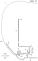
- FIG. 1 is a perspective view of a seat back according to a first embodiment
- FIG. 5 is an exploded perspective view of the side board and the back board as viewed from the front;
- the seat back 1 includes a pair of left and right side boards that are assembled to both left and right side portions of the back frame 10 from the rear, and that are fitted to both left and right end portions of the back board 40 from the front.
- Each of the side boards 30 is a vertical plate-shaped member elongated in a height direction along a respective one of the side portions of the back frame 10 .
- Each of the side boards 30 is formed of resin and has a U-shaped cross section that opens forward as viewed from above (see FIGS. 9 to 11 ).
- Each of the side boards 30 protrudes outward from a respective one of the side portions of the back frame 10 in the seat width direction.
- a front surface portion of each of the side boards 30 supports, from the rear, each rear end portion of the back pad 50 covering both side surface portions of the back frame 10 from an outside in the seat width direction.
- a fitting portion between each of the side boards 30 and the back board 40 is implemented as a fitting portion at which solid objects are fitted to each other. Accordingly, unlike a configuration in which the back board 40 and the back pad 50 are directly fitted to each other, when the finger of the occupant is put on the fitting portion between the back board 40 and each of the side boards 30 , it is possible to prevent the finger from entering the inside of the back board 40 without widening the gap of the above-described fitting portion.
- the side board 30 corresponds to an “intermediate board” according to the present disclosure.
- the back frame 10 is formed of metal.
- the back frame 10 includes vertically long plate-shaped side frames 13 that form side skeletons on both the left and right, a horizontally long plate-shaped upper frame 11 that extends between upper portions of the side frames 13 , and a horizontally long plate-shaped lower frame 12 that extends between lower portions of the side frames 13 .
- Each of the side frames 13 includes a reclining plate 14 connected to a seat cushion (not shown) on both left and right outer sides of a lower portion of the side frame 13 .
- the upper frame 11 forms an upper skeleton and has a U-shaped cross section that opens rearward in a side view (see FIG. 12 ).
- a headrest (not shown) serving as a headrest portion for the seated person is attached to an upper portion of the seat back 1 , and the upper frame 11 includes, on an upper surface thereof, two holders 15 that are arranged in the seat width direction and into which a headrest stay (not shown) is inserted from above (see FIG. 2 ).
- the back frame 10 includes a bracket 20 that is welded over each of the side frames 13 in a manner of covering the U-shaped opening of the upper frame 11 from the rear.
- the bracket 20 includes a horizontally long plate-shaped covering portion 21 provided behind the upper frame 11 , and welded portions 22 that extend from both left and right ends of the covering portion 21 and that are welded to upper portions of the side frames 13 .
- the bracket 20 is integrally formed with the back frame 10 by a part of a peripheral edge of each of the welded portions 22 being welded to a respective one of the side frames 13 .
- the bracket 20 has circular insertion holes 23 formed at two symmetrical positions on the left and right of the covering portion 21 , and rectangular locking holes 24 formed at lower portions of the welded portions 22 .
- An upper portion of the back board 40 is coupled to the insertion holes 23 by clips C (see FIGS. 5 and 6 ) to be described later.
- Each of the insertion holes 23 is formed in a portion that protrudes in a convex shape toward the rear of the covering portion 21 . Accordingly, the clips C are easily inserted into the insertion holes 23 .
- Upper portions of the side boards 30 are coupled to the locking holes 24 by hooks 31 (see FIG. 5 ).
- each of the side boards 30 may be appropriately locked to a respective one of the side frames 13 so as not to form a gap over a wide range in the height direction.
- the side board 30 is assembled to the back frame 10 by the hooks 31 and the claws 32 described above.
- an angle ⁇ between the locking surface 42 b and the abutting surface 34 a in the present embodiment is set to an angle of approximately 30 degrees.
- the lower claw 43 a of the inserted lower coupling portion 43 is locked to the inner edge of the coupling hole 34 .
- the lower claw 43 a has a configuration in which the locking surface 43 b abutting against the peripheral edge of the coupling hole 34 faces and abuts against the abutting surface 34 a of the coupling hole 34 straight in the front-rear direction.
- the intermediate coupling portions 42 are decoupled from the side boards 30 .
- an intermediate region of the back board 40 in the height direction receives a relatively high body pressure action from a vicinity of a waist of the seated person.
- the above-described intermediate region of the back board 40 is coupled to the side boards 30 . Therefore, the load applied to the vicinity of the waist of the seated person may be appropriately released by decoupling the intermediate coupling portions 42 .
- the clips C having large coupling forces do not come off from the bracket 20 even if the clips C receive the above-described load. Accordingly, the back board is not completely decoupled from the back frame 10 , and there is no concern that the back board 40 falls out rearward. Even if the back board 40 receives a large load toward the rear due to the above-described rear collision, as shown in FIG. 13 , the fitting holes 41 a of the clip attachment portions 41 are supported by the insertion portions C 1 and the seat surface portions C 3 in a state of being prevented from coming off in the front-rear direction. Accordingly, it is possible to prevent the coupling of the clip attachment portions 41 and the clips C from being decoupled.
- the back board 40 Even if the back board 40 receives a large force lifted from below due to the rear collision, the back board 40 is prevented from being decoupled upward from the clips C. Specifically, as shown in FIG. 6 , the clips C are attached to the clip attachment portions 41 from above. Accordingly, lower edges of the fitting holes 41 a are pressed against the clips C even if the back board 40 is lifted. Accordingly, it is possible to cause the upper portion of the back board 40 to be less likely to come off due to the above-described lifting force.
- a seat back ( 1 ) includes, on a back thereof, a back board ( 40 ) serving as a decorative plate.
- the seat back ( 1 ) includes: a back frame ( 10 ) that is configured to support a load of a seated person; a back pad ( 50 ) that is disposed at a front side of the back frame ( 10 ), is configured to support a load of a seated person and has elasticity; an intermediate board ( 30 ) that is interposed at a fitting portion of a peripheral edge between the back pad ( 50 ) and the back board ( 40 ); and a back cover ( 60 ) that is placed over the back pad ( 50 ) and the intermediate board ( 30 ).
- the peripheral edge of the back board ( 40 ) is fitted to the intermediate board ( 30 ). Therefore, it is possible to prevent a finger from entering an inside without expanding the fitting portion when the finger is hung. Further, the back cover ( 60 ) is placed between the intermediate board ( 30 ) and the back pad ( 50 ), so that it is possible to prevent the finger from entering the inside.
- An end of the back cover ( 60 ) is pulled between the intermediate board ( 30 ) and the back board ( 40 ).
- the end of the back cover ( 60 ) may be pulled into the back board ( 40 ) and fastened with good appearance.
- a pair of the intermediate boards ( 30 ) are provided on both outer side portions of the back frame ( 10 ) in a seat width direction, and are fixed to side frames ( 13 ) on both side portions of the back frame ( 10 ).
- the back board ( 40 ) is disposed over the pair of intermediate boards ( 30 ), and is fixed to the back frame ( 10 ) and/or the pair of intermediate boards ( 30 ).
- the intermediate boards ( 30 ) may prevent a finger from entering the inside from both side edge portions of the back board ( 40 ) in the seat width direction.
- the back board ( 40 ) includes a first coupling portion (C) to be coupled to the back frame ( 10 ) and second coupling portions ( 42 , 43 ) to be coupled to the back frame ( 10 ) and/or the intermediate boards ( 30 ) with a smaller coupling force than the first coupling portion (C).
- first coupling portion (C) to be coupled to the back frame ( 10 )
- second coupling portions ( 42 , 43 ) to be coupled to the back frame ( 10 ) and/or the intermediate boards ( 30 ) with a smaller coupling force than the first coupling portion (C).
- the second coupling portions ( 42 , 43 ) are decoupled from an engaged state, so that the excessive load from the front of the seat may be released. Further, by providing the second coupling portions ( 42 , 43 ), it is possible to easily control a position at which the load on the back board ( 40 ) is likely to be released.
- the first coupling portion (C) is coupled to an upper frame ( 11 ) of the back frame ( 10 ), and the second coupling portions ( 42 , 43 ) are coupled to the pair of intermediate boards ( 30 ) at a position lower than that of the first coupling portion (C).
- a coupling state of a portion coupled at a position lower than that of the upper frame ( 11 ) of the back board ( 40 ) is likely to be released. Accordingly, a load applied to a portion where a body pressure of the seated person is high is likely to be released.
- the first coupling portion (C) is implemented such that a clip (C) detachably attached to a clip attachment portion ( 41 ) of the back board ( 40 ) is inserted into an insertion hole of the back frame ( 10 ) from the rear and is locked by snap fitting on both sides of a peripheral edge of the insertion hole in a direction orthogonal to an insertion direction.
- the second coupling portions ( 42 , 43 ) are implemented such that a claw protruding from the back board ( 40 ) is inserted into a coupling hole of the intermediate board ( 30 ) from the rear and is locked by snap fitting only on one side of a peripheral edge of the coupling hole in a direction orthogonal to an insertion direction.
- the first coupling portion (C) may be firmly coupled with a simple configuration in which the clip (C) is simply inserted from the rear. Further, the clip (C) is attachable and detachable, so that the back board ( 40 ) may be easily removed from the back frame ( 10 ), and maintainability may be improved.
- the clip attachment portion ( 41 ) is opened upward so that the clip (C) may be fitted from above.
- the clip (C) when an excessive load is applied from the front of the seat, the clip (C) is less likely to come off the back board ( 40 ). Further, even if the back board ( 40 ) receives a force lifted from below due to the above-described load, it is possible that the clip attachment portion ( 41 ) is less likely to come off from the clip (C).
- the intermediate board ( 30 ) extends between the upper frame ( 11 ) and a lower frame ( 12 ) of the back frame ( 10 ) along the side frame ( 13 ).
- the second coupling portions ( 42 , 43 ) include an intermediate coupling portion ( 42 ) provided below the first coupling portion (C), and a lower coupling portion ( 43 ) that is provided below the intermediate coupling portion ( 42 ) and that is coupled with a larger coupling force than the intermediate coupling portion ( 42 ).
- the intermediate coupling portion ( 42 ), to which the body pressure of the seated person is likely to be strongly applied, is more likely to come off. Accordingly, the load applied to the seated person may be more appropriately released.
- the intermediate coupling portions ( 42 ) are provided at a plurality of positions in an upper-lower direction.
- an interval between the intermediate coupling portions ( 42 ) may be narrowed. Accordingly, it is possible to appropriately couple the back board ( 40 ) to a fitting portion with the intermediate board ( 30 ) such that a gap is less likely to be formed.
Landscapes
- Engineering & Computer Science (AREA)
- Aviation & Aerospace Engineering (AREA)
- Transportation (AREA)
- Mechanical Engineering (AREA)
- Chair Legs, Seat Parts, And Backrests (AREA)
- Seats For Vehicles (AREA)
Abstract
Description
-
- 1. The seat back may also be widely applied to a seat provided for a vehicle other than an automobile such as a railway, or various vehicles such as an aircraft and a ship.
- 2. The intermediate board may be an upper board that covers the upper frame from the rear in addition to the side board that covers the side frame from the rear. Alternatively, the intermediate board may continuously cover the side frame and the upper frame from the rear. Alternatively, the intermediate board may be a single plate member provided continuously over the pair of left and right side frames. In addition to a configuration of the pair of left and right side boards, the side board may be provided on only one side of the left and right.
- 3. The back board may be fixed only to the back frame or may be fixed only to the pair of intermediate boards. The first coupling portion may couple the back board to the back frame with a screw or a bolt, in addition to the clip. The first coupling portion may be coupled to the side frame or the lower frame of the back frame. The first coupling portion may be coupled to the intermediate board. The second coupling portion may be coupled at a position higher than that of the first coupling portion. The second coupling portion may be coupled to the back frame.
- 4. The intermediate coupling portion may be provided at only one position in the upper-lower direction, or may be provided at three or more positions. The intermediate claw of the intermediate coupling portion may be inclined at an angle smaller than 30 degrees with respect to the abutting surface of the coupling hole. Further, as long as the intermediate claw may be locked to the coupling hole, the intermediate claw may be inclined at a larger angle. The lower coupling portions may be provided at a plurality of positions in the upper-lower direction.
- 5. The back cover may be placed over the back board.
- 6. The clip may be attached in a manner of not being attachable to and detachable from the back board. The clip may be attached to the clip attachment portion in the left-right direction or from below.
Claims (8)
Applications Claiming Priority (2)
| Application Number | Priority Date | Filing Date | Title |
|---|---|---|---|
| JP2021-187642 | 2021-11-18 | ||
| JP2021187642A JP7815705B2 (en) | 2021-11-18 | seat back |
Publications (2)
| Publication Number | Publication Date |
|---|---|
| US20230150411A1 US20230150411A1 (en) | 2023-05-18 |
| US12269385B2 true US12269385B2 (en) | 2025-04-08 |
Family
ID=86325036
Family Applications (1)
| Application Number | Title | Priority Date | Filing Date |
|---|---|---|---|
| US17/987,041 Active 2043-04-16 US12269385B2 (en) | 2021-11-18 | 2022-11-15 | Seat back |
Country Status (2)
| Country | Link |
|---|---|
| US (1) | US12269385B2 (en) |
| CN (1) | CN116135076A (en) |
Families Citing this family (2)
| Publication number | Priority date | Publication date | Assignee | Title |
|---|---|---|---|---|
| US12208716B2 (en) * | 2022-06-16 | 2025-01-28 | Ford Global Technologies, Llc | Flexible upper frame adapter for traditional back frame and seat back assemblies |
| US12365465B2 (en) * | 2023-08-28 | 2025-07-22 | Textron Innovations Inc. | One piece seat back panel |
Citations (64)
| Publication number | Priority date | Publication date | Assignee | Title |
|---|---|---|---|---|
| US4065182A (en) * | 1976-08-30 | 1977-12-27 | General Motors Corporation | Cushion retention for a vehicle seat |
| US5522645A (en) * | 1994-04-01 | 1996-06-04 | Milsco Manufacturing Company | Seat having retained cushion |
| US5895096A (en) * | 1997-04-10 | 1999-04-20 | Lear Corporation | Vehicle seat back assembly and method of making a vehicle seat back assembly |
| US5918943A (en) * | 1996-02-05 | 1999-07-06 | Mercedes-Benz Ag | Vehicle seat assembly with backrest frame swivelbly coupled with a seat frame |
| US5938284A (en) * | 1996-07-19 | 1999-08-17 | Cascade Engineering, Inc. | Seat bolster adjustment assembly |
| US5988757A (en) * | 1996-08-29 | 1999-11-23 | Lear Corporation | Vehicle seat assembly |
| US6048033A (en) * | 1997-01-21 | 2000-04-11 | Suzuki Motor Corporation | Seat back frame |
| US6082823A (en) * | 1998-04-17 | 2000-07-04 | Betrand Faure Equipments S.A. | Backrest framework of an automobile vehicle seat |
| JP2002142913A (en) | 2000-11-10 | 2002-05-21 | Johnson Controls Automotive Systems Corp | Mounting structure of back board of seat back for vehicle |
| US20040183356A1 (en) * | 2003-02-21 | 2004-09-23 | Faurecia Sieges D'automobile S.A. | Backrest of an automobile vehicle seat |
| US20040227389A1 (en) * | 2003-03-31 | 2004-11-18 | Masami Yoshida | Seat back frame for vehicle seat |
| US6994401B1 (en) * | 2000-09-14 | 2006-02-07 | Lear Corporation | Seat backrest cover module |
| US20090102270A1 (en) * | 2007-10-23 | 2009-04-23 | Toyota Boshoku Kabushiki Kaisha | Seat backs for vehicular seats |
| US7559607B2 (en) * | 2004-12-20 | 2009-07-14 | Baultar I.D. Inc. | Adjustable ergonomic back for a seat |
| US20130082504A1 (en) * | 2011-09-29 | 2013-04-04 | Baultar I.D. Inc. | Modular seat assembly |
| US8465092B2 (en) * | 2010-03-04 | 2013-06-18 | Tachi-S Co., Ltd. | Seat back framework |
| US8469446B2 (en) * | 2011-01-14 | 2013-06-25 | Tachi-S Co. Ltd. | Seat back framework |
| US20140084661A1 (en) * | 2011-06-16 | 2014-03-27 | Toyota Jidosha Kabushiki Kaisha | Seat backboard and vehicle seat |
| US8894154B2 (en) * | 2009-03-02 | 2014-11-25 | Faurecia Automotive Seating, Inc. | Seat back including integrated backrest and reinforcing composite layer |
| US20150008716A1 (en) * | 2013-07-02 | 2015-01-08 | Ford Global Technologies, Llc | Trim attachment apparatus for vehicle seating assembly |
| US9090188B2 (en) * | 2012-07-24 | 2015-07-28 | Toyota Boshoku Kabushiki Kaisha | Vehicular seats |
| DE102015203910A1 (en) * | 2014-03-07 | 2015-09-10 | Toyota Boshoku Kabushiki Kaisha | Transportation seat |
| US20150251579A1 (en) * | 2014-03-04 | 2015-09-10 | Ford Global Technologies, Llc | Trim and foam assembly for a vehicle seat |
| US20150314501A1 (en) * | 2014-05-02 | 2015-11-05 | Reliant Worldwide Plastics, Llc | Method and system for homogenous thermoplastic seat back assembly |
| JP2015199366A (en) * | 2014-04-04 | 2015-11-12 | トヨタ紡織株式会社 | vehicle seat |
| US20150336490A1 (en) * | 2014-05-20 | 2015-11-26 | Toyota Boshoku Kabushiki Kaisha | Vehicle seat |
| US20150367762A1 (en) * | 2014-06-24 | 2015-12-24 | Nhk Spring Co., Ltd. | Vehicle seat |
| US20160001689A1 (en) * | 2014-07-03 | 2016-01-07 | Nhk Spring Co., Ltd. | Vehicle seat |
| JP2016016847A (en) * | 2014-07-11 | 2016-02-01 | トヨタ紡織株式会社 | Vehicular seat |
| US20160096450A1 (en) * | 2014-10-03 | 2016-04-07 | Ford Global Technologies, Llc | Tuned flexible support member and flexible suspension features for comfort carriers |
| US20160272097A1 (en) * | 2013-10-28 | 2016-09-22 | Maciej Szymanski | A method for manufacturing of upholstery, in particular for mass transit vehicle chairs, and an upholstery, in particular for mass transit vehicle chairs |
| US9707873B2 (en) * | 2013-01-24 | 2017-07-18 | Ford Global Technologies, Llc | Flexible seatback system |
| US9718385B2 (en) * | 2014-05-27 | 2017-08-01 | Nhk Spring Co., Ltd. | Vehicle seat |
| US20170283070A1 (en) * | 2016-04-01 | 2017-10-05 | MIRUS Aircraft Seating Ltd. | Seat Back for Vehicle |
| US20170334326A1 (en) * | 2016-05-18 | 2017-11-23 | Ford Global Technologies, Llc | Vehicle seat and headrest with dynamic impact energy management system |
| US9834166B1 (en) * | 2016-06-07 | 2017-12-05 | Ford Global Technologies, Llc | Side airbag energy management system |
| US9845032B1 (en) * | 2016-08-05 | 2017-12-19 | Ford Global Technologies, Llc | Modular back panel sub-assembly |
| US9849856B1 (en) * | 2016-06-07 | 2017-12-26 | Ford Global Technologies, Llc | Side airbag energy management system |
| US9868374B2 (en) * | 2016-03-18 | 2018-01-16 | Ami Industries, Inc. | Modular monocoque backrest |
| US10046682B2 (en) * | 2015-08-03 | 2018-08-14 | Ford Global Technologies, Llc | Back cushion module for a vehicle seating assembly |
| US20180319301A1 (en) * | 2017-05-05 | 2018-11-08 | Lear Corporation | Seat assembly having a shell disposed on a seat back frame |
| US10220750B2 (en) * | 2016-08-05 | 2019-03-05 | Ford Global Technologies, Llc | Inner carrier substrate mechanical lock with head restraint guide sleeves |
| US10220745B2 (en) * | 2016-08-05 | 2019-03-05 | Ford Global Technologies, Llc | Inner carrier substrate trim cover attachment |
| US10272800B2 (en) * | 2014-12-17 | 2019-04-30 | Bentley Motors Limited | Seat |
| US10300818B2 (en) * | 2016-09-15 | 2019-05-28 | Toyota Boshoku Kabushiki Kaisha | Vehicle seat |
| US20190176665A1 (en) * | 2017-12-13 | 2019-06-13 | Tachi-S Co., Ltd. | Seat back board, trim cover and vehicle seat |
| US20190210498A1 (en) * | 2018-01-11 | 2019-07-11 | Ts Tech Co., Ltd. | Seatback structure |
| US20190225180A1 (en) * | 2018-01-24 | 2019-07-25 | Ford Global Technologies, Llc | Seat cover assembly |
| US10471862B2 (en) * | 2017-12-05 | 2019-11-12 | Lear Corporation | Vehicle seat with resilient insert |
| US10576856B2 (en) * | 2015-10-14 | 2020-03-03 | Safran Seats Usa Llc | Passenger seat including a net backrest |
| US20200406798A1 (en) * | 2019-06-26 | 2020-12-31 | Lear Corporation | Upper seatback support block |
| US20210061140A1 (en) * | 2019-09-04 | 2021-03-04 | Toyota Jidosha Kabushiki Kaisha | Vehicle-mounted seat device |
| US11260780B2 (en) * | 2019-09-25 | 2022-03-01 | Toyota Jidosha Kabushiki Kaisha | Vehicle-mounted seat device |
| US11285853B1 (en) * | 2020-12-21 | 2022-03-29 | Ford Global Technologies, Llc | Modular seating assembly |
| US20220176856A1 (en) * | 2020-12-09 | 2022-06-09 | Faurecia Sièges d'Automobile | Vehicle seat backrest |
| US11453320B1 (en) * | 2021-03-31 | 2022-09-27 | Lear Corporation | Seat assembly and seatback |
| US20220340059A1 (en) * | 2021-04-23 | 2022-10-27 | Toyota Boshoku Kabushiki Kaisha | Seat device |
| US20220340060A1 (en) * | 2021-04-23 | 2022-10-27 | Toyota Boshoku Kabushiki Kaisha | Seat device |
| US20230055017A1 (en) * | 2021-08-23 | 2023-02-23 | Lippert Components, Inc. | Devices and method to removably secure a seatback shell to a seatback frame |
| US20230302975A1 (en) * | 2022-03-22 | 2023-09-28 | Faurecia Sièges d'Automobile | Support element for a vehicle seat, associated vehicle seat and assembly method |
| US11787320B2 (en) * | 2021-01-06 | 2023-10-17 | Adient Us Llc | Seat back panel |
| US20230406176A1 (en) * | 2022-06-16 | 2023-12-21 | Adient Us Llc | Backrest for a vehicle seat and a method for mounting |
| US20230406177A1 (en) * | 2022-06-16 | 2023-12-21 | Ford Global Technologies, Llc | Flexible upper frame adapter for traditional back frame and seat back assemblies |
| US11850981B2 (en) * | 2019-04-30 | 2023-12-26 | Adient Us Llc | Lightweight cushion suspension and seating surface |
Family Cites Families (3)
| Publication number | Priority date | Publication date | Assignee | Title |
|---|---|---|---|---|
| JP4255867B2 (en) * | 2004-03-17 | 2009-04-15 | 本田技研工業株式会社 | Vehicle seat |
| JP5989884B2 (en) * | 2015-10-26 | 2016-09-07 | 富士重工業株式会社 | Vehicle seat |
| CN109760565A (en) * | 2019-01-29 | 2019-05-17 | 广汽零部件有限公司 | An integrated car seat back plastic back plate assembly and seat back |
-
2022
- 2022-11-15 US US17/987,041 patent/US12269385B2/en active Active
- 2022-11-17 CN CN202211439641.8A patent/CN116135076A/en active Pending
Patent Citations (67)
| Publication number | Priority date | Publication date | Assignee | Title |
|---|---|---|---|---|
| US4065182A (en) * | 1976-08-30 | 1977-12-27 | General Motors Corporation | Cushion retention for a vehicle seat |
| US5522645A (en) * | 1994-04-01 | 1996-06-04 | Milsco Manufacturing Company | Seat having retained cushion |
| US5918943A (en) * | 1996-02-05 | 1999-07-06 | Mercedes-Benz Ag | Vehicle seat assembly with backrest frame swivelbly coupled with a seat frame |
| US5938284A (en) * | 1996-07-19 | 1999-08-17 | Cascade Engineering, Inc. | Seat bolster adjustment assembly |
| US6019428A (en) * | 1996-07-19 | 2000-02-01 | Cascade Engineering | Seat bolster adjustment assembly |
| US5988757A (en) * | 1996-08-29 | 1999-11-23 | Lear Corporation | Vehicle seat assembly |
| US6048033A (en) * | 1997-01-21 | 2000-04-11 | Suzuki Motor Corporation | Seat back frame |
| US5895096A (en) * | 1997-04-10 | 1999-04-20 | Lear Corporation | Vehicle seat back assembly and method of making a vehicle seat back assembly |
| US6082823A (en) * | 1998-04-17 | 2000-07-04 | Betrand Faure Equipments S.A. | Backrest framework of an automobile vehicle seat |
| US6994401B1 (en) * | 2000-09-14 | 2006-02-07 | Lear Corporation | Seat backrest cover module |
| JP2002142913A (en) | 2000-11-10 | 2002-05-21 | Johnson Controls Automotive Systems Corp | Mounting structure of back board of seat back for vehicle |
| US20040183356A1 (en) * | 2003-02-21 | 2004-09-23 | Faurecia Sieges D'automobile S.A. | Backrest of an automobile vehicle seat |
| US20040227389A1 (en) * | 2003-03-31 | 2004-11-18 | Masami Yoshida | Seat back frame for vehicle seat |
| US7559607B2 (en) * | 2004-12-20 | 2009-07-14 | Baultar I.D. Inc. | Adjustable ergonomic back for a seat |
| US20090102270A1 (en) * | 2007-10-23 | 2009-04-23 | Toyota Boshoku Kabushiki Kaisha | Seat backs for vehicular seats |
| US8894154B2 (en) * | 2009-03-02 | 2014-11-25 | Faurecia Automotive Seating, Inc. | Seat back including integrated backrest and reinforcing composite layer |
| US8465092B2 (en) * | 2010-03-04 | 2013-06-18 | Tachi-S Co., Ltd. | Seat back framework |
| US8469446B2 (en) * | 2011-01-14 | 2013-06-25 | Tachi-S Co. Ltd. | Seat back framework |
| US20140084661A1 (en) * | 2011-06-16 | 2014-03-27 | Toyota Jidosha Kabushiki Kaisha | Seat backboard and vehicle seat |
| US20130082504A1 (en) * | 2011-09-29 | 2013-04-04 | Baultar I.D. Inc. | Modular seat assembly |
| US9090188B2 (en) * | 2012-07-24 | 2015-07-28 | Toyota Boshoku Kabushiki Kaisha | Vehicular seats |
| US9873362B2 (en) * | 2013-01-24 | 2018-01-23 | Ford Global Technologies, Llc | Flexible seatback system |
| US9707873B2 (en) * | 2013-01-24 | 2017-07-18 | Ford Global Technologies, Llc | Flexible seatback system |
| US20150008716A1 (en) * | 2013-07-02 | 2015-01-08 | Ford Global Technologies, Llc | Trim attachment apparatus for vehicle seating assembly |
| US20160272097A1 (en) * | 2013-10-28 | 2016-09-22 | Maciej Szymanski | A method for manufacturing of upholstery, in particular for mass transit vehicle chairs, and an upholstery, in particular for mass transit vehicle chairs |
| US20150251579A1 (en) * | 2014-03-04 | 2015-09-10 | Ford Global Technologies, Llc | Trim and foam assembly for a vehicle seat |
| DE102015203910A1 (en) * | 2014-03-07 | 2015-09-10 | Toyota Boshoku Kabushiki Kaisha | Transportation seat |
| JP2015199366A (en) * | 2014-04-04 | 2015-11-12 | トヨタ紡織株式会社 | vehicle seat |
| US20150314501A1 (en) * | 2014-05-02 | 2015-11-05 | Reliant Worldwide Plastics, Llc | Method and system for homogenous thermoplastic seat back assembly |
| US20150336490A1 (en) * | 2014-05-20 | 2015-11-26 | Toyota Boshoku Kabushiki Kaisha | Vehicle seat |
| US9718385B2 (en) * | 2014-05-27 | 2017-08-01 | Nhk Spring Co., Ltd. | Vehicle seat |
| US20150367762A1 (en) * | 2014-06-24 | 2015-12-24 | Nhk Spring Co., Ltd. | Vehicle seat |
| US20160001689A1 (en) * | 2014-07-03 | 2016-01-07 | Nhk Spring Co., Ltd. | Vehicle seat |
| JP2016016847A (en) * | 2014-07-11 | 2016-02-01 | トヨタ紡織株式会社 | Vehicular seat |
| US20160096450A1 (en) * | 2014-10-03 | 2016-04-07 | Ford Global Technologies, Llc | Tuned flexible support member and flexible suspension features for comfort carriers |
| US10272800B2 (en) * | 2014-12-17 | 2019-04-30 | Bentley Motors Limited | Seat |
| US10046682B2 (en) * | 2015-08-03 | 2018-08-14 | Ford Global Technologies, Llc | Back cushion module for a vehicle seating assembly |
| US10576856B2 (en) * | 2015-10-14 | 2020-03-03 | Safran Seats Usa Llc | Passenger seat including a net backrest |
| US9868374B2 (en) * | 2016-03-18 | 2018-01-16 | Ami Industries, Inc. | Modular monocoque backrest |
| US10071661B2 (en) * | 2016-03-18 | 2018-09-11 | Ami Industries, Inc. | Modular monocoque backrest |
| US20170283070A1 (en) * | 2016-04-01 | 2017-10-05 | MIRUS Aircraft Seating Ltd. | Seat Back for Vehicle |
| US20170334326A1 (en) * | 2016-05-18 | 2017-11-23 | Ford Global Technologies, Llc | Vehicle seat and headrest with dynamic impact energy management system |
| US9834166B1 (en) * | 2016-06-07 | 2017-12-05 | Ford Global Technologies, Llc | Side airbag energy management system |
| US9849856B1 (en) * | 2016-06-07 | 2017-12-26 | Ford Global Technologies, Llc | Side airbag energy management system |
| US10220745B2 (en) * | 2016-08-05 | 2019-03-05 | Ford Global Technologies, Llc | Inner carrier substrate trim cover attachment |
| US9845032B1 (en) * | 2016-08-05 | 2017-12-19 | Ford Global Technologies, Llc | Modular back panel sub-assembly |
| US10220750B2 (en) * | 2016-08-05 | 2019-03-05 | Ford Global Technologies, Llc | Inner carrier substrate mechanical lock with head restraint guide sleeves |
| US10300818B2 (en) * | 2016-09-15 | 2019-05-28 | Toyota Boshoku Kabushiki Kaisha | Vehicle seat |
| US20180319301A1 (en) * | 2017-05-05 | 2018-11-08 | Lear Corporation | Seat assembly having a shell disposed on a seat back frame |
| US10471862B2 (en) * | 2017-12-05 | 2019-11-12 | Lear Corporation | Vehicle seat with resilient insert |
| US20190176665A1 (en) * | 2017-12-13 | 2019-06-13 | Tachi-S Co., Ltd. | Seat back board, trim cover and vehicle seat |
| US20190210498A1 (en) * | 2018-01-11 | 2019-07-11 | Ts Tech Co., Ltd. | Seatback structure |
| US20190225180A1 (en) * | 2018-01-24 | 2019-07-25 | Ford Global Technologies, Llc | Seat cover assembly |
| US11850981B2 (en) * | 2019-04-30 | 2023-12-26 | Adient Us Llc | Lightweight cushion suspension and seating surface |
| US20200406798A1 (en) * | 2019-06-26 | 2020-12-31 | Lear Corporation | Upper seatback support block |
| US20210061140A1 (en) * | 2019-09-04 | 2021-03-04 | Toyota Jidosha Kabushiki Kaisha | Vehicle-mounted seat device |
| US11260780B2 (en) * | 2019-09-25 | 2022-03-01 | Toyota Jidosha Kabushiki Kaisha | Vehicle-mounted seat device |
| US20220176856A1 (en) * | 2020-12-09 | 2022-06-09 | Faurecia Sièges d'Automobile | Vehicle seat backrest |
| US11285853B1 (en) * | 2020-12-21 | 2022-03-29 | Ford Global Technologies, Llc | Modular seating assembly |
| US11787320B2 (en) * | 2021-01-06 | 2023-10-17 | Adient Us Llc | Seat back panel |
| US11453320B1 (en) * | 2021-03-31 | 2022-09-27 | Lear Corporation | Seat assembly and seatback |
| US20220340059A1 (en) * | 2021-04-23 | 2022-10-27 | Toyota Boshoku Kabushiki Kaisha | Seat device |
| US20220340060A1 (en) * | 2021-04-23 | 2022-10-27 | Toyota Boshoku Kabushiki Kaisha | Seat device |
| US20230055017A1 (en) * | 2021-08-23 | 2023-02-23 | Lippert Components, Inc. | Devices and method to removably secure a seatback shell to a seatback frame |
| US20230302975A1 (en) * | 2022-03-22 | 2023-09-28 | Faurecia Sièges d'Automobile | Support element for a vehicle seat, associated vehicle seat and assembly method |
| US20230406176A1 (en) * | 2022-06-16 | 2023-12-21 | Adient Us Llc | Backrest for a vehicle seat and a method for mounting |
| US20230406177A1 (en) * | 2022-06-16 | 2023-12-21 | Ford Global Technologies, Llc | Flexible upper frame adapter for traditional back frame and seat back assemblies |
Non-Patent Citations (1)
| Title |
|---|
| Japanese Office Action issued in JP 2021-187642, dated Jan. 14, 2025, along with a machine English translation thereof. |
Also Published As
| Publication number | Publication date |
|---|---|
| JP2023074625A (en) | 2023-05-30 |
| US20230150411A1 (en) | 2023-05-18 |
| CN116135076A (en) | 2023-05-19 |
Similar Documents
| Publication | Publication Date | Title |
|---|---|---|
| US12269385B2 (en) | Seat back | |
| CN107487237A (en) | Vehicle seat | |
| JP2019001280A (en) | Vehicle seat | |
| US6634710B1 (en) | Vehicle seat assembly having child seat attachments | |
| US10525855B2 (en) | Vehicle seat | |
| JP2017218126A (en) | Vehicle seat | |
| CN113498389A (en) | Covering for a cushion part of a vehicle seat, cushion part of a vehicle seat and vehicle seat | |
| US10442319B2 (en) | Vehicle seat | |
| JP4193242B2 (en) | Vehicle seat structure | |
| US20250121746A1 (en) | Vehicle tether structure | |
| JP7815705B2 (en) | seat back | |
| JP6469191B2 (en) | Skin material suspension structure | |
| US10421378B2 (en) | Vehicle seat | |
| JP2021087648A (en) | Mounting frame | |
| JP2004114917A (en) | Vehicle seats with headrests for attaching child seats | |
| JP6204123B2 (en) | Skin material suspension structure | |
| CN113508055A (en) | Covering for a cushion part of a vehicle seat, cushion part of a vehicle seat and vehicle seat | |
| KR100401725B1 (en) | Structure for mounting a rear seat cushion and child seat on a vehicle body | |
| US20250121781A1 (en) | Tether cover structure | |
| JP4467843B2 (en) | Vehicle seat cushion | |
| CN214138311U (en) | Fastening components for the pull straps on the child seat | |
| US20250214495A1 (en) | Seat | |
| JP2020124978A (en) | Vehicular seat | |
| JP7237619B2 (en) | vehicle seat | |
| JP2024125096A (en) | Seat cushion mounting structure and vehicle seat |
Legal Events
| Date | Code | Title | Description |
|---|---|---|---|
| AS | Assignment |
Owner name: TOYOTA BOSHOKU KABUSHIKI KAISHA, JAPAN Free format text: ASSIGNMENT OF ASSIGNORS INTEREST;ASSIGNORS:MAEDA, MICHITAKA;KUNO, TSUBASA;ESAKI, MAKOTO;SIGNING DATES FROM 20220627 TO 20220718;REEL/FRAME:061774/0629 |
|
| FEPP | Fee payment procedure |
Free format text: ENTITY STATUS SET TO UNDISCOUNTED (ORIGINAL EVENT CODE: BIG.); ENTITY STATUS OF PATENT OWNER: LARGE ENTITY |
|
| STPP | Information on status: patent application and granting procedure in general |
Free format text: DOCKETED NEW CASE - READY FOR EXAMINATION |
|
| STPP | Information on status: patent application and granting procedure in general |
Free format text: NON FINAL ACTION MAILED |
|
| STPP | Information on status: patent application and granting procedure in general |
Free format text: FINAL REJECTION MAILED |
|
| STPP | Information on status: patent application and granting procedure in general |
Free format text: ADVISORY ACTION MAILED |
|
| STPP | Information on status: patent application and granting procedure in general |
Free format text: RESPONSE AFTER FINAL ACTION FORWARDED TO EXAMINER |
|
| STPP | Information on status: patent application and granting procedure in general |
Free format text: NOTICE OF ALLOWANCE MAILED -- APPLICATION RECEIVED IN OFFICE OF PUBLICATIONS |
|
| STPP | Information on status: patent application and granting procedure in general |
Free format text: NOTICE OF ALLOWANCE MAILED -- APPLICATION RECEIVED IN OFFICE OF PUBLICATIONS |
|
| STPP | Information on status: patent application and granting procedure in general |
Free format text: PUBLICATIONS -- ISSUE FEE PAYMENT VERIFIED |
|
| STCF | Information on status: patent grant |
Free format text: PATENTED CASE |