US12268560B2 - Device and method for supplying power to an ultrasound transducer - Google Patents
Device and method for supplying power to an ultrasound transducer Download PDFInfo
- Publication number
- US12268560B2 US12268560B2 US18/006,378 US202118006378A US12268560B2 US 12268560 B2 US12268560 B2 US 12268560B2 US 202118006378 A US202118006378 A US 202118006378A US 12268560 B2 US12268560 B2 US 12268560B2
- Authority
- US
- United States
- Prior art keywords
- ultrasonic
- signal
- digital
- delta
- drive signal
- Prior art date
- Legal status (The legal status is an assumption and is not a legal conclusion. Google has not performed a legal analysis and makes no representation as to the accuracy of the status listed.)
- Active, expires
Links
Images


Classifications
-
- B—PERFORMING OPERATIONS; TRANSPORTING
- B06—GENERATING OR TRANSMITTING MECHANICAL VIBRATIONS IN GENERAL
- B06B—METHODS OR APPARATUS FOR GENERATING OR TRANSMITTING MECHANICAL VIBRATIONS OF INFRASONIC, SONIC, OR ULTRASONIC FREQUENCY, e.g. FOR PERFORMING MECHANICAL WORK IN GENERAL
- B06B1/00—Methods or apparatus for generating mechanical vibrations of infrasonic, sonic, or ultrasonic frequency
- B06B1/02—Methods or apparatus for generating mechanical vibrations of infrasonic, sonic, or ultrasonic frequency making use of electrical energy
- B06B1/0207—Driving circuits
- B06B1/0223—Driving circuits for generating signals continuous in time
- B06B1/0238—Driving circuits for generating signals continuous in time of a single frequency, e.g. a sine-wave
-
- A—HUMAN NECESSITIES
- A61—MEDICAL OR VETERINARY SCIENCE; HYGIENE
- A61B—DIAGNOSIS; SURGERY; IDENTIFICATION
- A61B8/00—Diagnosis using ultrasonic, sonic or infrasonic waves
- A61B8/56—Details of data transmission or power supply
-
- A—HUMAN NECESSITIES
- A61—MEDICAL OR VETERINARY SCIENCE; HYGIENE
- A61N—ELECTROTHERAPY; MAGNETOTHERAPY; RADIATION THERAPY; ULTRASOUND THERAPY
- A61N7/00—Ultrasound therapy
-
- B—PERFORMING OPERATIONS; TRANSPORTING
- B06—GENERATING OR TRANSMITTING MECHANICAL VIBRATIONS IN GENERAL
- B06B—METHODS OR APPARATUS FOR GENERATING OR TRANSMITTING MECHANICAL VIBRATIONS OF INFRASONIC, SONIC, OR ULTRASONIC FREQUENCY, e.g. FOR PERFORMING MECHANICAL WORK IN GENERAL
- B06B1/00—Methods or apparatus for generating mechanical vibrations of infrasonic, sonic, or ultrasonic frequency
- B06B1/02—Methods or apparatus for generating mechanical vibrations of infrasonic, sonic, or ultrasonic frequency making use of electrical energy
- B06B1/0207—Driving circuits
- B06B1/0215—Driving circuits for generating pulses, e.g. bursts of oscillations, envelopes
-
- G—PHYSICS
- G01—MEASURING; TESTING
- G01N—INVESTIGATING OR ANALYSING MATERIALS BY DETERMINING THEIR CHEMICAL OR PHYSICAL PROPERTIES
- G01N29/00—Investigating or analysing materials by the use of ultrasonic, sonic or infrasonic waves; Visualisation of the interior of objects by transmitting ultrasonic or sonic waves through the object
- G01N29/04—Analysing solids
- G01N29/06—Visualisation of the interior, e.g. acoustic microscopy
- G01N29/0654—Imaging
-
- G—PHYSICS
- G01—MEASURING; TESTING
- G01N—INVESTIGATING OR ANALYSING MATERIALS BY DETERMINING THEIR CHEMICAL OR PHYSICAL PROPERTIES
- G01N29/00—Investigating or analysing materials by the use of ultrasonic, sonic or infrasonic waves; Visualisation of the interior of objects by transmitting ultrasonic or sonic waves through the object
- G01N29/34—Generating the ultrasonic, sonic or infrasonic waves, e.g. electronic circuits specially adapted therefor
- G01N29/346—Generating the ultrasonic, sonic or infrasonic waves, e.g. electronic circuits specially adapted therefor with amplitude characteristics, e.g. modulated signal
-
- B—PERFORMING OPERATIONS; TRANSPORTING
- B06—GENERATING OR TRANSMITTING MECHANICAL VIBRATIONS IN GENERAL
- B06B—METHODS OR APPARATUS FOR GENERATING OR TRANSMITTING MECHANICAL VIBRATIONS OF INFRASONIC, SONIC, OR ULTRASONIC FREQUENCY, e.g. FOR PERFORMING MECHANICAL WORK IN GENERAL
- B06B2201/00—Indexing scheme associated with B06B1/0207 for details covered by B06B1/0207 but not provided for in any of its subgroups
- B06B2201/70—Specific application
- B06B2201/76—Medical, dental
-
- G—PHYSICS
- G01—MEASURING; TESTING
- G01N—INVESTIGATING OR ANALYSING MATERIALS BY DETERMINING THEIR CHEMICAL OR PHYSICAL PROPERTIES
- G01N2291/00—Indexing codes associated with group G01N29/00
- G01N2291/02—Indexing codes associated with the analysed material
- G01N2291/024—Mixtures
- G01N2291/02475—Tissue characterisation
-
- G—PHYSICS
- G01—MEASURING; TESTING
- G01N—INVESTIGATING OR ANALYSING MATERIALS BY DETERMINING THEIR CHEMICAL OR PHYSICAL PROPERTIES
- G01N2291/00—Indexing codes associated with group G01N29/00
- G01N2291/10—Number of transducers
- G01N2291/106—Number of transducers one or more transducer arrays
-
- H—ELECTRICITY
- H03—ELECTRONIC CIRCUITRY
- H03M—CODING; DECODING; CODE CONVERSION IN GENERAL
- H03M3/00—Conversion of analogue values to or from differential modulation
- H03M3/30—Delta-sigma modulation
-
- H—ELECTRICITY
- H03—ELECTRONIC CIRCUITRY
- H03M—CODING; DECODING; CODE CONVERSION IN GENERAL
- H03M3/00—Conversion of analogue values to or from differential modulation
- H03M3/30—Delta-sigma modulation
- H03M3/50—Digital/analogue converters using delta-sigma modulation as an intermediate step
Definitions
- the present invention relates to a device and a method for supplying an ultrasonic transducer. It also relates to an ultrasonic device comprising such a supply device, and an ultrasonic system comprising such an ultrasonic device.
- Ultrasonic transducers are widely used in the medical field, in particular for medical imaging, for example for ultrasound examination, but also for medical therapy. To do this, the transducers are typically arranged in a matrix, also called an “ultrasonic head”, in order to transmit focused and high-power ultrasounds in the area to be imaged or treated. Each ultrasonic transducer is supplied by a sinusoidal signal at a given frequency so as to generate an ultrasonic signal of said frequency.
- the ultrasonic head comprises, for each ultrasonic transducer, an individual control chain. This latter makes it possible to modify, individually for each transducer, the amplitude of the ultrasonic signal transmitted by said transducer, but also its frequency and its phase. Thus, the characteristics of the ultrasonic wave transmitted by each transducer of the matrix can be modified.
- One aim of the present invention is to solve at least one of the above-mentioned shortcomings.
- Another aim of the present invention is to propose a device for supplying an ultrasonic transducer that is more efficient in terms of performance.
- Another aim of the present invention is to propose a device for supplying an ultrasonic transducer that is less bulky.
- the device according to the invention makes it possible to supply the ultrasonic transducer with a better quality supply signal, and with improved performance relative to the known control chains.
- the delta-sigma modulator makes it possible to provide a delta-sigma modulated sinusoidal signal for controlling a lower-cost and simple power interface.
- the supply signal of the transducer contains harmonics located in the high frequencies outside of its bandwidth.
- the delta-sigma modulator can be made in the form of a digital component so that the supply device is less cumbersome, compared to currently known analog control chains.
- the use of a delta-sigma modulator makes it possible to avoid the use of a filter dedicated to harmonic elimination, which further reduces the size of the supply device according to the invention.
- the delta-sigma modulator may be a 4 th order modulator.
- the delta-sigma modulator may comprise a single-bit output quantizer such that the control signal is modulated over one bit.
- Such a digital control interface may be, or may comprise, a digital communication interface intended to receive data representing at least one of the listed parameters, from an external control device.
- the digital control interface may be provided to perform wireless communication with the external control device.
- the supply device according to the invention may be integrated, partly or entirely, into at least one digital component, such as an electronic chip or a processor, in particular programmable.
- the delta-sigma modulator may be integrated into a digital component, such as an electronic chip or a processor, in particular programmable, with the digital signal generator, and/or the digital control interface.
- a digital component such as an electronic chip or a processor, in particular programmable
- the ultrasonic transducer may be a transducer of any type.
- the ultrasonic head according to the invention can be used for medical imaging, in particular for ultrasound imaging.
- the ultrasonic head according to the invention can be used for medical therapy.
- each ultrasonic device receives the data concerning the ultrasonic wave to be generated from said common digital control device.
- the common digital control device may be connected to the ultrasonic devices by a wired digital communication bus.
- said common digital control device can be connected to said ultrasonic devices by an optical connection.
- the system according to the invention may be a medical therapy system.
- system according to the invention may be an ecotherapy system.
- the system according to the invention may be an aesthetic treatment system.
- a method for supplying an ultrasonic transducer with an analog power signal, called supply signal characterized in that it comprises the following steps:
- the method according to the invention can comprise, in terms of method, any combination of at least one feature described above, and which are not repeated herein for the sake of brevity.
- FIG. 2 is a schematic depiction of a non-limiting example of examples of signals in the device of FIG. 1 ;
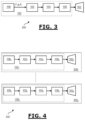
- FIG. 4 is a schematic depiction of a non-limiting exemplary embodiment of an ultrasonic head according to the invention.
- FIG. 5 is a schematic depiction of a non-limiting exemplary embodiment of an ultrasonic system according to the invention.
- the device 100 shown in FIG. 1 , is provided to supply an ultrasonic transducer, for example, in an ultrasonic transducer of an ultrasonic head for medical use.
- the supply device 100 comprises a digital sinusoidal signal generator 102 that generates a digital sinusoidal signal, i.e. a sinusoidal signal represented in digital form, and called the drive signal hereinafter.
- This digital generator 102 can be any digital electronic component programmed or designed to deliver, in digital form, the sinusoidal drive signal, as a function of the parameters relating to the sinusoidal signal to be generated.
- the parameters entered into the digital generator 102 may comprise:
- the DS converter 104 may comprise a single-bit or multi-bit output quantizer.
- control interface is optional and the features of the sinusoidal signal may be communicated directly to the digital generator 102 .
- the ultrasonic device 300 depicted in FIG. 3 comprises an ultrasonic transducer 302 powered by a supply device according to the invention, and in particular the supply device 100 of FIG. 1 .
- At least two of the ultrasonic devices 300 1 - 300 n may be identical or different.
- FIG. 5 is a schematic depiction of a non-limiting exemplary of an ultrasound system according to the invention.
- the ultrasound system 500 of FIG. 5 comprises an ultrasonic head according to the invention, such as for example the ultrasonic head 400 of FIG. 4 .
- the ultrasonic system 500 further comprises a control device 502 , such as a computer or a tablet, and more generally any computer device, connected to each ultrasonic device 300 i of the ultrasonic head 400 , and in particular to the control interface 108 i of said ultrasonic device.
- a control device 502 such as a computer or a tablet, and more generally any computer device, connected to each ultrasonic device 300 i of the ultrasonic head 400 , and in particular to the control interface 108 i of said ultrasonic device.
- control device 502 is connected to each control interface 108 i via a communication bus 504 that is digital and wired 504 .
- each control interface 108 i may be in communication with the control device 502 through a wireless link.
- FIG. 6 is a schematic depiction of another non-limiting exemplary embodiment of an ultrasonic system according to the invention.
- FIG. 6 illustrates a variant of FIG. 5 , wherein the system 600 , shown in FIG. 6 , has a head 602 composed of a plurality of ‘n’ composite ultrasonic devices 604 1 to 604 n .
- a same common interface 108 i controls a plurality of supply devices that each supply one and only one transducer.
- a same common interface 108 1 controls a plurality of ‘k’ supply devices 100 11 to 100 1k , which each supply one and only one transducer 302 11 to 302 1k .
- the block 604 n comprises a single digital interface 108 n that directly drives the ‘m’ supply devices 100 n1 to 100 nm of the transducers respectively 302 n1 to 302 nm .
- the matrix then consists of a multitude of transducers, which are associated in ‘n’ groups comprising an identical or different number of transducers.
- the number of transducers in a given group is small, for example in a number from 2 to 16.
Landscapes
- Health & Medical Sciences (AREA)
- Life Sciences & Earth Sciences (AREA)
- Engineering & Computer Science (AREA)
- General Health & Medical Sciences (AREA)
- Physics & Mathematics (AREA)
- Pathology (AREA)
- Radiology & Medical Imaging (AREA)
- Nuclear Medicine, Radiotherapy & Molecular Imaging (AREA)
- Animal Behavior & Ethology (AREA)
- Public Health (AREA)
- Veterinary Medicine (AREA)
- Biomedical Technology (AREA)
- Mechanical Engineering (AREA)
- Analytical Chemistry (AREA)
- Immunology (AREA)
- General Physics & Mathematics (AREA)
- Biochemistry (AREA)
- Chemical & Material Sciences (AREA)
- Biophysics (AREA)
- Medical Informatics (AREA)
- Molecular Biology (AREA)
- Surgery (AREA)
- Heart & Thoracic Surgery (AREA)
- Computer Networks & Wireless Communication (AREA)
- Acoustics & Sound (AREA)
- Ultra Sonic Daignosis Equipment (AREA)
- Percussion Or Vibration Massage (AREA)
- Surgical Instruments (AREA)
- Apparatuses For Generation Of Mechanical Vibrations (AREA)
- Transducers For Ultrasonic Waves (AREA)
Abstract
Description
-
- a frequency of said drive signal,
- an amplitude of said drive signal,
- a phase of said drive signal.
-
- a data item relating to a frequency of said drive signal,
- a data item relating to an amplitude of said drive signal,
- a data item relating to a phase of said drive signal.
-
- at least one ultrasonic transducer, and
- a supply device according to the invention for supplying said at least one ultrasonic transducer.
-
- an ultrasonic head according to the invention, and
- at least one digital control device for the ultrasonic devices of said ultrasonic head.
-
- delta-sigma modulation of a sinusoidal signal, called drive signal, to provide a signal, called control signal;
- controlling a power interface with said delta-sigma modulated control signal, to provide said supply signal.
-
- the frequency F, and/or
- the phase φ, and/or
- the amplitude A
of the sinusoidal signal to be generated.
-
- the
signal 202 corresponds to the curve that represents the digital signal supplied by thegenerator 102 to the DS modulator; - the signal 204 corresponds to the delta-sigma modulated control signal produced by the
DS converter 104, which, in this example, has a single-bit output, by virtue of thesignal 202 and - the signal 206 corresponds to the spectrum of the signal produced by the
interface 106 that supplies the transducer. This signal is, in this example, produced by a DS modulator of the 4th single-bit order.
- the
Claims (12)
Applications Claiming Priority (4)
| Application Number | Priority Date | Filing Date | Title |
|---|---|---|---|
| FRFR2008136 | 2020-07-30 | ||
| FR2008136 | 2020-07-30 | ||
| FR2008136A FR3113148B1 (en) | 2020-07-30 | 2020-07-30 | Device and method for supplying an ultrasonic transducer |
| PCT/EP2021/070955 WO2022023316A1 (en) | 2020-07-30 | 2021-07-27 | Device and method for supplying power to an ultrasound transducer |
Publications (2)
| Publication Number | Publication Date |
|---|---|
| US20230255603A1 US20230255603A1 (en) | 2023-08-17 |
| US12268560B2 true US12268560B2 (en) | 2025-04-08 |
Family
ID=73013700
Family Applications (1)
| Application Number | Title | Priority Date | Filing Date |
|---|---|---|---|
| US18/006,378 Active 2041-12-06 US12268560B2 (en) | 2020-07-30 | 2021-07-27 | Device and method for supplying power to an ultrasound transducer |
Country Status (5)
| Country | Link |
|---|---|
| US (1) | US12268560B2 (en) |
| EP (1) | EP4188620A1 (en) |
| JP (1) | JP2023541515A (en) |
| FR (1) | FR3113148B1 (en) |
| WO (1) | WO2022023316A1 (en) |
Citations (8)
| Publication number | Priority date | Publication date | Assignee | Title |
|---|---|---|---|---|
| JPH105218A (en) | 1996-06-20 | 1998-01-13 | Ge Yokogawa Medical Syst Ltd | Ultrasonic vibrator driving method and device and ultrasonic imaging pickup device |
| US20140276065A1 (en) * | 2013-03-15 | 2014-09-18 | Infraredx, Inc. | High Resolution Intravascular Ultrasound Imaging Systems and Methods |
| US20150109056A1 (en) | 2013-10-23 | 2015-04-23 | Wolfson Microelectronics Plc | Class-d amplifier circuits |
| CN103167380B (en) | 2011-12-13 | 2015-09-09 | 中国科学院声学研究所 | A kind of digitlization audio beam loudspeaker system |
| CN205426862U (en) | 2015-12-10 | 2016-08-03 | 华南理工大学 | Supersound guided wave signal excitation collection moulding piece |
| US9692445B1 (en) * | 2016-03-17 | 2017-06-27 | Texas Instruments Incorporated | Sigma-delta modulator for generating a sinusoidal signal |
| US20190216426A1 (en) | 2016-09-29 | 2019-07-18 | Koninklijke Philips N.V. | Flexible phased array transducer for intravascular imaging device and associated devices, systems, and methods |
| US10613205B2 (en) * | 2014-10-06 | 2020-04-07 | Analog Devices, Inc. | Systems and methods for ultrasound beamforming |
-
2020
- 2020-07-30 FR FR2008136A patent/FR3113148B1/en active Active
-
2021
- 2021-07-27 WO PCT/EP2021/070955 patent/WO2022023316A1/en not_active Ceased
- 2021-07-27 US US18/006,378 patent/US12268560B2/en active Active
- 2021-07-27 JP JP2023506185A patent/JP2023541515A/en active Pending
- 2021-07-27 EP EP21752485.9A patent/EP4188620A1/en active Pending
Patent Citations (9)
| Publication number | Priority date | Publication date | Assignee | Title |
|---|---|---|---|---|
| JPH105218A (en) | 1996-06-20 | 1998-01-13 | Ge Yokogawa Medical Syst Ltd | Ultrasonic vibrator driving method and device and ultrasonic imaging pickup device |
| CN103167380B (en) | 2011-12-13 | 2015-09-09 | 中国科学院声学研究所 | A kind of digitlization audio beam loudspeaker system |
| US20140276065A1 (en) * | 2013-03-15 | 2014-09-18 | Infraredx, Inc. | High Resolution Intravascular Ultrasound Imaging Systems and Methods |
| US20150109056A1 (en) | 2013-10-23 | 2015-04-23 | Wolfson Microelectronics Plc | Class-d amplifier circuits |
| US10613205B2 (en) * | 2014-10-06 | 2020-04-07 | Analog Devices, Inc. | Systems and methods for ultrasound beamforming |
| CN205426862U (en) | 2015-12-10 | 2016-08-03 | 华南理工大学 | Supersound guided wave signal excitation collection moulding piece |
| US9692445B1 (en) * | 2016-03-17 | 2017-06-27 | Texas Instruments Incorporated | Sigma-delta modulator for generating a sinusoidal signal |
| US20190216426A1 (en) | 2016-09-29 | 2019-07-18 | Koninklijke Philips N.V. | Flexible phased array transducer for intravascular imaging device and associated devices, systems, and methods |
| JP2019530505A (en) | 2016-09-29 | 2019-10-24 | コーニンクレッカ フィリップス エヌ ヴェKoninklijke Philips N.V. | Flexible phased array transducer for intravascular imaging devices and related devices, systems and methods |
Non-Patent Citations (4)
| Title |
|---|
| Anonymous, "Delta-sigma modulation—Wikipedia", Mar. 25, 2020 (Mar. 25, 2020), Retrouvé de : URL:https://en.wikipedia.org/w/index.php?title=Delta-sigma_modulation&oldid=947299650, XP055793945. |
| International Search Report issued on Nov. 9, 2021 in corresponding International Patent Application No. PCT/EP2021/070955, 7 pages. |
| Office Action issued on Sep. 3, 2024, in corresponding Japanese Application No. 2023-506185, 8 pages. |
| Preliminary Search Report issued on Apr. 20, 2021 in corresponding French Patent Application No. 2008136, 18 pages. |
Also Published As
| Publication number | Publication date |
|---|---|
| FR3113148A1 (en) | 2022-02-04 |
| FR3113148B1 (en) | 2023-05-26 |
| EP4188620A1 (en) | 2023-06-07 |
| WO2022023316A1 (en) | 2022-02-03 |
| JP2023541515A (en) | 2023-10-03 |
| US20230255603A1 (en) | 2023-08-17 |
Similar Documents
| Publication | Publication Date | Title |
|---|---|---|
| US9681231B2 (en) | Digital/analog conversion apparatus | |
| US20200186922A1 (en) | Microphone assembly with digital feedback loop | |
| JP2001503929A (en) | Mixed signal processor for oversampled noise shaping | |
| US7286008B2 (en) | Digital amplifier | |
| CN1568477A (en) | Hybrid digital/analog processing circuit | |
| TW200818697A (en) | Low power output stage | |
| US12268560B2 (en) | Device and method for supplying power to an ultrasound transducer | |
| US7657238B2 (en) | Method and apparatus for modulating a radio signal using digital amplitude and phase control signals | |
| DE10117528B4 (en) | Ultrasonic based parametric multi-way speaker system | |
| CN100496405C (en) | Ultrasonic diagnosing device | |
| US20090112294A1 (en) | Biostimulative Illumination Apparatus | |
| US6469957B1 (en) | Arbitrary signal generator for driving ultrasonic transducers | |
| EP1248492B1 (en) | Ultrasonic parametric multiway speaker system | |
| US12419617B2 (en) | Device and synchronous method for supplying power to an ultrasound transducer | |
| KR100912110B1 (en) | Natural Ultrasonic Generator | |
| TWI356598B (en) | Signal generation power management control system | |
| CN116531233A (en) | Cervical vertebra auxiliary massaging device | |
| JP2011030047A (en) | Electrostatic electroacoustic transducer | |
| US7719377B2 (en) | Alternating digital RF modulation | |
| JP3822832B2 (en) | Transmission circuit of ultrasonic diagnostic equipment | |
| US12407259B2 (en) | Method and apparatus for suppressing audible buzz from high-efficiency switching-mode power supply | |
| JP2006087686A (en) | Ultrasonic beauty treatment apparatus | |
| CN117643673A (en) | Intelligent pillow control method and system and pillow | |
| US20250325403A1 (en) | Phaco driver system, a method and a computer program product | |
| US11375328B2 (en) | Extended bandwidth hearing aid with dynamically adjustable sampling rate for power optimized deployment of coordinated reset (CR) neuromodulation for the treatment of subjective tonal tinnitus |
Legal Events
| Date | Code | Title | Description |
|---|---|---|---|
| FEPP | Fee payment procedure |
Free format text: ENTITY STATUS SET TO UNDISCOUNTED (ORIGINAL EVENT CODE: BIG.); ENTITY STATUS OF PATENT OWNER: LARGE ENTITY |
|
| AS | Assignment |
Owner name: CENTRE NATIONAL DE LA RECHERCHE SCIENTIFIQUE, FRANCE Free format text: ASSIGNMENT OF ASSIGNORS INTEREST;ASSIGNORS:ZHANG, MING;LLASER, NICOLAS;SIGNING DATES FROM 20210905 TO 20210909;REEL/FRAME:062458/0044 Owner name: UNIVERSITE PARIS-SACLAY, FRANCE Free format text: ASSIGNMENT OF ASSIGNORS INTEREST;ASSIGNORS:ZHANG, MING;LLASER, NICOLAS;SIGNING DATES FROM 20210905 TO 20210909;REEL/FRAME:062458/0044 |
|
| STPP | Information on status: patent application and granting procedure in general |
Free format text: DOCKETED NEW CASE - READY FOR EXAMINATION |
|
| STPP | Information on status: patent application and granting procedure in general |
Free format text: NON FINAL ACTION MAILED |
|
| STPP | Information on status: patent application and granting procedure in general |
Free format text: RESPONSE TO NON-FINAL OFFICE ACTION ENTERED AND FORWARDED TO EXAMINER |
|
| STPP | Information on status: patent application and granting procedure in general |
Free format text: NOTICE OF ALLOWANCE MAILED -- APPLICATION RECEIVED IN OFFICE OF PUBLICATIONS |
|
| STPP | Information on status: patent application and granting procedure in general |
Free format text: PUBLICATIONS -- ISSUE FEE PAYMENT VERIFIED |
|
| STCF | Information on status: patent grant |
Free format text: PATENTED CASE |