US12263872B2 - Track-changing device for a pneumatic transport vehicle - Google Patents
Track-changing device for a pneumatic transport vehicle Download PDFInfo
- Publication number
- US12263872B2 US12263872B2 US17/428,473 US202017428473A US12263872B2 US 12263872 B2 US12263872 B2 US 12263872B2 US 202017428473 A US202017428473 A US 202017428473A US 12263872 B2 US12263872 B2 US 12263872B2
- Authority
- US
- United States
- Prior art keywords
- track
- mobile
- turnout
- beams
- propulsion
- Prior art date
- Legal status (The legal status is an assumption and is not a legal conclusion. Google has not performed a legal analysis and makes no representation as to the accuracy of the status listed.)
- Active, expires
Links
- 230000007246 mechanism Effects 0.000 claims abstract description 36
- 238000002955 isolation Methods 0.000 claims abstract description 17
- 238000007789 sealing Methods 0.000 claims description 24
- 230000000295 complement effect Effects 0.000 claims description 8
- 238000012423 maintenance Methods 0.000 claims description 5
- 239000000463 material Substances 0.000 claims description 4
- 239000012528 membrane Substances 0.000 claims description 4
- 241000269350 Anura Species 0.000 claims description 3
- 238000009795 derivation Methods 0.000 claims description 2
- 238000009987 spinning Methods 0.000 claims 1
- 230000006872 improvement Effects 0.000 abstract description 6
- 230000008859 change Effects 0.000 description 9
- 238000006073 displacement reaction Methods 0.000 description 4
- 230000006870 function Effects 0.000 description 4
- 238000006243 chemical reaction Methods 0.000 description 3
- 238000009434 installation Methods 0.000 description 3
- 230000008901 benefit Effects 0.000 description 2
- 238000010276 construction Methods 0.000 description 2
- 239000012530 fluid Substances 0.000 description 2
- 241000713838 Avian myeloblastosis virus Species 0.000 description 1
- 230000009471 action Effects 0.000 description 1
- 230000000903 blocking effect Effects 0.000 description 1
- 230000008878 coupling Effects 0.000 description 1
- 238000010168 coupling process Methods 0.000 description 1
- 238000005859 coupling reaction Methods 0.000 description 1
- 230000003028 elevating effect Effects 0.000 description 1
- 238000004519 manufacturing process Methods 0.000 description 1
- 238000000034 method Methods 0.000 description 1
- 230000008569 process Effects 0.000 description 1
- 230000002035 prolonged effect Effects 0.000 description 1
- 230000009467 reduction Effects 0.000 description 1
- 238000000926 separation method Methods 0.000 description 1
- 230000002459 sustained effect Effects 0.000 description 1
- 230000007704 transition Effects 0.000 description 1
- 230000000007 visual effect Effects 0.000 description 1
Images


Classifications
-
- E—FIXED CONSTRUCTIONS
- E01—CONSTRUCTION OF ROADS, RAILWAYS, OR BRIDGES
- E01B—PERMANENT WAY; PERMANENT-WAY TOOLS; MACHINES FOR MAKING RAILWAYS OF ALL KINDS
- E01B25/00—Tracks for special kinds of railways
- E01B25/16—Tracks for aerial rope railways with a stationary rope
- E01B25/20—Switches; Crossings
-
- B—PERFORMING OPERATIONS; TRANSPORTING
- B61—RAILWAYS
- B61B—RAILWAY SYSTEMS; EQUIPMENT THEREFOR NOT OTHERWISE PROVIDED FOR
- B61B13/00—Other railway systems
- B61B13/12—Systems with propulsion devices between or alongside the rails, e.g. pneumatic systems
- B61B13/122—Pneumatic systems
-
- E—FIXED CONSTRUCTIONS
- E01—CONSTRUCTION OF ROADS, RAILWAYS, OR BRIDGES
- E01B—PERMANENT WAY; PERMANENT-WAY TOOLS; MACHINES FOR MAKING RAILWAYS OF ALL KINDS
- E01B25/00—Tracks for special kinds of railways
-
- E—FIXED CONSTRUCTIONS
- E01—CONSTRUCTION OF ROADS, RAILWAYS, OR BRIDGES
- E01B—PERMANENT WAY; PERMANENT-WAY TOOLS; MACHINES FOR MAKING RAILWAYS OF ALL KINDS
- E01B7/00—Switches; Crossings
-
- B—PERFORMING OPERATIONS; TRANSPORTING
- B61—RAILWAYS
- B61B—RAILWAY SYSTEMS; EQUIPMENT THEREFOR NOT OTHERWISE PROVIDED FOR
- B61B5/00—Elevated railway systems without suspended vehicles
-
- B—PERFORMING OPERATIONS; TRANSPORTING
- B61—RAILWAYS
- B61J—SHIFTING OR SHUNTING OF RAIL VEHICLES
- B61J3/00—Shunting or short-distance haulage devices; Similar devices for hauling trains on steep gradients or as starting aids; Car propelling devices therefor
- B61J3/08—Devices with reciprocated pushing bars or like driving mechanisms combined with the track for shunting or hauling cars
Definitions
- the present invention refers to an improvement developed on a pneumatic transport system for loads and/or passengers whose vehicles are not provided with on-board drive means, being guided on two exclusive tracks arranged in parallel, each track being dedicated to one travel direction, resulting in high transport capacity.
- the invention consists of a diagonal track, commonly known as crossover, which connects the two referred parallel tracks, as well as to the track-changing device installed in both ends, allowing transposing a vehicle from one line to the other.
- a pivoting valve is comprised for the physical separation of the pneumatic propulsion circuits of the vehicles, the section isolating valves, applied both in the crossbeams as in strategic points throughout the entire track, allowing the concomitant and independent operation of multiple vehicles.
- the change in track consists in an arrangement on the rails that enables changing the direction of the train in a bifurcation.
- this change in track is executed by the Track Switching Apparatus—AMV and can consist of two types: manual, which are activated by a lever, and the electric, which are activated by a switch machine.
- AMV Track Switching Apparatus
- a part known as a rod transmits the lever or switch machine movement to the gate, which consists of a tapered mobile part to adapt to the back rail or gate.
- These gates have articulation points and move simultaneously in the direction required by the lever or the switch machine causing the change in track.
- a pneumatic propulsion vehicle has a mast for sustaining a plate which fills the interior of the section of the duct through which there is airflow.
- the top of the duct presents a longitudinal slot located between the rails, through which the mast of the propulsion plate passes.
- the conventional AMVs are not suitable for the rails positioned over the pneumatic propulsion ducts, since they use an interconnecting rod of the tracks, which obstructs the passage of the mast of the actuator plate of the pneumatic vehicle.
- Patent documents PI 7703372-8, PI 7906255-5, PI 8301706-2, PI 8503504-1, PI 9502056-0, PI 9814160-0, PI 9912112-3, PI 0805188-7 and PI 0901119-6 describe a pneumatic transport system which is comprised of light vehicles comprising, preferably, bogies containing four metallic wheels each, being at least one of the shafts connected to a mast screwed to a propulsion plate, which is responsible for the conversion of the thrust of the fluid in mechanical work for movement of the vehicles over railways laid over a special elevated track.
- the elevated track is further characterized by consisting in the propulsion duct thereof, device in charge of the creation of the physical means for contention and propagation of the air flow generated by stationary power-unit groups.
- the power-unit groups are responsible for elevating or reducing the manometric pressure in the hollow interior of the beams which form the elevated track.
- this slot can be sealed by the physical positioning of the two pairs of sealing flaps formed by highly resistant and durable material, excellent mechanical memory and low surface friction.
- Patent document BR 10 2014 014409 9 presents an improvement over the prior arrangement. It is disclosed that over the propulsion duct table where the fixed and mobile tracks are laid there are further anchored the respective drive sets by means of pre-existing inserts on the concrete surface. These sets are formed by cams eliminating the inconvenient torque tubes system for actuation. There is further introduced a locking system for the mobile tracks.
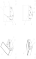
- FIG. 1 front view of the pneumatic transport vehicle over the double elevated track of the state of the art
- FIG. 2 front view of the sealing of the longitudinal slot of the propulsion duct of the elevated track during the passage of the mast of the plate of the vehicle of the state of the art;
- FIG. 3 front view of the closed sealing of the longitudinal slot of the propulsion ducts of the elevated track of the state of the art
- FIG. 4 perspective of the crossbeam set of the invention in normal position
- FIG. 5 schematic upper view of the crossbeam of the invention
- FIG. 6 sectioned perspectives of the sealing terminal of the longitudinal slot of the propulsion duct of the turnout beam
- FIG. 7 upper view of the complete crossbeam in normal position
- FIG. 8 upper view of the complete crossbeam in turnout position
- FIG. 9 Endlarged detail of rectangle A indicated in FIG. 7 ;
- FIG. 10 Endlarged detail of rectangle B indicated in FIG. 7
- FIG. 11 Endlarged detail of rectangle C indicated in FIG. 8 ;
- FIG. 12 Enlarged detail of rectangle D indicated in FIG. 8 ;
- FIG. 13 Perspective of the drive mechanism of the segments on the mobile rails, as per sub-rectangle A 2 indicated in FIG. 9 ;
- FIG. 14 Upper view of the drive mechanism of the segments of the mobile tracks as per sub-rectangle A 2 indicated in FIG. 9 ;
- FIG. 15 Perspective of the drive mechanism of the intermediary tracks as per sub-rectangle B 1 indicated in FIG. 10 ;
- FIG. 16 Upper view of the drive mechanism of the intermediary tracks as per sub-rectangle B 1 indicated in FIG. 10 ;
- FIG. 17 Perspective of the locking mechanism of the mobile rails of sub-rectangle A 1 indicated in FIG. 9 ;
- FIG. 18 Upper view of the locking mechanism of the mobile rails as per sub-rectangle A 1 indicated in FIG. 9 ;
- FIG. 19 Perspective of the section isolation valve in the closed position
- FIG. 20 Perspective of the section isolation valve in the open position
- FIG. 21 Cut of the section isolation valve in the closed position, according to line AA indicated in FIG. 23 ;
- FIG. 22 AA cut of the section isolation valve in the open position
- FIG. 23 Upper schematic view of the crossbeam indicating the section isolation valve.
- FIG. 1 illustrates the two-way pneumatic propulsion system of the state of the art which consists of vehicles ( 1 ), preferably comprising two or more bogies, each one comprised of four metallic wheels ( 2 ), whereby one of the shafts is connected to a mast ( 3 ) fixed to a propulsion plate ( 4 ) which is the one responsible for the conversion of the fluid thrust of the compressed air current in mechanical work.
- the vehicles ( 1 ) travel over railway tracks ( 5 ) laid over elevated tracks supported by pillars ( 7 ).
- FIGS. 2 and 3 detail the general aspect of the state of the art of the seal ( 8 ) of the longitudinal slot ( 9 ).
- the seal ( 8 ) consists of two profiles placed one in front of the other, each one fixed by a set of screws and metallic pressure bars ( 10 ), anchored to the elevated track ( 6 ) by means of pre-existing inserts ( 11 ).
- the tabs of the seal profile ( 8 ) move away generating space for the displacement of the mast ( 3 ) of the vehicle propulsion plate, as illustrated in FIG. 2 .
- FIG. 3 illustrates the tabs of the seal profile ( 8 ) in the rest position.
- FIG. 4 illustrates the set formed by the crossbeam over the tracks ( 5 ) in tangent route, being sustained by pillars ( 7 ), with a central pillar having a transverse conceived to support the double head of each one of the two turnout beams in the position where the bifurcation of the propulsion duct ( 12 ) occurs in two distinct ducts.
- the crossbeam region is comprised by four beams which constitute the superstructure of the elevated track, being two turnout beams ( 6 ′) and two straight beams ( 6 ′′).
- the four beams ( 6 and 6 ′) are permanently connected to each other and to the pillars ( 7 ) in the region of the heads in order to form a monolithic hyperstatic structured in the form of a portico.
- FIG. 5 divides the structures of the crossbeam according to the material which they consist of, while at the same time it identifies the specific sealing position of the turnout.
- the turnout beams ( 6 ′) have a lower slab, lateral walls and part of the upper slab constructed in concrete, which comprises a complementary metallic part ( 13 ) connected in balance, to allow the unobstructed passage of the vehicle propulsion plate inside the propulsion duct during the change of track maneuver.
- the complementary metallic part ( 13 ) is projected to have minimum vertical displacement during the intermittent pressurizing and depressurizing cycles of the duct in normal working conditions.
- a sealing terminal ( 14 ) of the longitudinal slot ( 9 ) of the bifurcation of the turnout beam ( 6 ′) is executed in flexible material and fixed at the end of the complementary metallic part ( 13 ), in the opposite direction to the bifurcation of the track.
- the sealing terminal ( 14 ) enables the derivation from a single seal of the slot ( 9 ) of the straight beam ( 6 ′′) to a second sealing that is necessary for the suitable tightness of the propulsion duct of the turnout beam ( 6 ′).
- FIG. 6 details the transition of the sealing of the slot in the duct from the straight to the turnout and is divided in seven distinct representations (A to G), showing the transverse section of the terminal ( 14 ) in distinct points of interest where a significant change in geometry takes place, starting from the known set of two profiles ( 8 ) in the cut represented in (A), until it transforms into two sets united to each other (G).
- the terminal ( 14 ) is in one piece, which proximal end presents only two “V” shaped profiles laid down which are opposite and separated ( 14 a ).
- the intermediary portion of the terminal ( 14 ) has a vertical membrane ( 14 b ) which begins the bifurcation of the sealing tabs of each one of the slots of the turnout.
- the distal end of the terminal ( 14 ) has a horizontal membrane ( 14 c ) which interconnects the two pairs of sealing tabs for the two turnout slots. In its distal end there continues the common shape of the seal profile ( 8 ) by means of the in loco seam.
- FIGS. 7 and 8 illustrate the set of the crossbeam in their normal position and in turnout, respectively, being emphasized the alignment of the tracks of the route of the vehicle (RV and RV′) in both situations.
- FIGS. 9 , 10 , 11 and 12 emphasize the positioning of the mobile rails ( 16 , 18 and 21 ), and show the drive mechanisms ( 17 , 19 and 20 ), and locking ( 15 ) associated thereto, as indicated in rectangles A and B of FIG. 7 and in rectangles C and D of FIG. 8 , in this order.
- the first mechanism is comprised by a pivoting rail to be moved individually, as occurs with the gates ( 16 ) and the frogs ( 21 ).
- the second mechanism is comprised of two rails directly connected, without a connecting rod between them, being the sole case of the intermediary rails ( 18 ).
- the position of the mobile rails ( 16 , 18 and 21 ) is monitored by redundant sensors that are positioned on the surface of the turnout beams ( 6 ′) next to the rails themselves, therefore not being an integral part of the drive mechanisms ( 17 , 19 and 20 ).
- FIGS. 13 and 14 illustrate by themselves the drive mechanism ( 17 ) of the gates ( 16 ), as per the marking of the sub-rectangle A 2 of FIG. 9 .
- FIGS. 15 and 16 illustrate by themselves the drive mechanism ( 19 ) of the intermediary tracks ( 18 ), as per the marking on sub-rectangle B 1 of FIG. 10 .
- FIGS. 17 and 18 illustrate the locking mechanism ( 15 ) of the mobile rails ( 16 , 18 and 21 ), as per the marking of sub-rectangle A 1 of FIG. 9 .
- the gates ( 16 ) and the frog ( 21 ) have similar drive mechanisms ( 17 and 20 ). Differently from the frog ( 21 ), however, the drive mechanisms ( 17 ) of the gates ( 16 ) have an additional anchorage ( 22 ) in their respective back rail (counter-gate), apart from the one existing on the surface of the turnout beam ( 6 ′).
- the angular movement of the gates ( 16 ) is possible by means of the introduction of a hinge type flexible splint between them and the connection rail.
- the frog ( 21 ) moves by means of an internal pin located in one of its extremities.
- the drive mechanisms ( 17 and 20 ) are comprised of a single base plate ( 23 ) over which rests a linear actuator ( 24 ), preferably pneumatic, which dislodges two articulation bars in their central point, being one primary articulation bar ( 25 ) connected to a route regulator ( 26 ) and the other articulation secondary bar ( 27 ) screwed directly on the mobile rail ( 16 or 21 —not illustrated) for the conduction thereof.
- the regulation is carried out by means of the fine adjustment of an eccentric axis which is locked by a flange with a screw.
- the complete device has its movement limited by a stop limit ( 28 ) in the shape of a support pin, with identical regulation to the former.
- the two intermediary mobile rails ( 18 ) have a drive mechanism ( 19 ) which is similar in concept to the gates ( 16 ) and the mobile frog ( 21 ), however, adapted for the simultaneous drive in two rail segments.
- the linear actuator ( 29 ) activates a lever ( 30 ) turning consequently an eccentric ( 31 ) which, in turn, moves simultaneously both the articulation bar ( 32 ) connected to the mobile rail ( 18 —not illustrated) to be aligned for the tangent passage, as the articulation bar ( 33 ) connected to the mobile rail ( 18 —not illustrated) to be aligned for reverse passage.
- the drive mechanism ( 19 ) has two limit stops ( 34 ) to, equally, ensure the maintenance of the position of the respective alignment, whereby the support is provided against one of the faces of the extremity that is opposite to that of the lever ( 30 ).
- the redundant position locking mechanism ( 15 ) of each mobile rail ( 16 , 18 and 21 ) foresees the unauthorized movement of same when facing an improbable spurious command from the automatic control system for working of the respective actuator ( 24 and 29 ) of the drive system ( 17 , 19 , and 20 ).
- the locking mechanism is identical for all the mobile rails ( 16 , 18 and 21 —not illustrated). It consists of a support base ( 35 ) screwed to the fixed track and wherein there are fixed a linear actuator ( 36 ), preferably pneumatic, the sliding lock ( 37 ) and the position sensors ( 38 ).
- the lock fitting ( 39 ) is screwed to the mobile rail ( 16 , 18 and 21 —not illustrated), and may have one or two recesses.
- the support base ( 35 ) further accumulates the supplementary function of stop limit for the intermediary rails ( 18 ) and frog ( 21 ).
- FIGS. 19 and 20 illustrate the section isolation valve prominently and in the closed and open positions, respectively.
- FIGS. 21 and 22 illustrate the section isolation valve mounted on the rail ( 6 ) and respectively in the closed and open positions. In the closed position the airflow is obstructed inside the propulsion duct ( 12 ) by the presence of the shutter ( 40 ).
- a linear actuator ( 41 ) preferably pneumatic, activates a set of two articulated rods ( 42 ) until the position of the stop limit ( 43 ).
- the angle formed between the articulated structures ( 42 ) characterizes the valve as being “monostable” remaining in safe closed position, even in the absence of pneumatic pressure in the linear actuator ( 41 ) or in the improbable collapse of its rod.
- a positive locking with safety pin positioned on the base of the lower articulated rod ( 42 ), which counts on two orifices each, to guarantee the locking both in the open or closed position, even if the linear actuator ( 41 ) is erroneously commanded to move.
- FIG. 23 indicates the hold position ( 44 ) for coupling of the section isolation valve inside the junction of the propulsion ducts ( 12 ) of the two turnout beams ( 6 ′) which form the crossbeam.
Landscapes
- Engineering & Computer Science (AREA)
- Mechanical Engineering (AREA)
- Architecture (AREA)
- Civil Engineering (AREA)
- Structural Engineering (AREA)
- Transportation (AREA)
- Chemical & Material Sciences (AREA)
- Combustion & Propulsion (AREA)
- Train Traffic Observation, Control, And Security (AREA)
Abstract
Description
-
- Diagonal rail (crossbeam) which connects two parallel rails, allowing the vehicle to transpose and change track, comprising an internal pneumatic propulsion duct and supporting pillars;
- Mobile rails arranged over the diagonal rail stand which are comprised of gates, intermediary rails and frogs.
- Drive and safety locking mechanisms of the mobile rails which are of the safefail type and comprise linear actuators, rods and stops, whereby the locking mechanisms have identical mechanical configuration for all types of mobile rails;
- Section isolation valve which is positioned inside the propulsion duct of the vehicle in the diagonal track;
- Mechanical sealing complement for the propulsion duct in the bifurcation region of the diagonal track, allowing the operation under higher air pressure levels;
- Sealing terminal for the propulsion duct slot in the diagonal track during the displacement of the mast of the propulsion plate of the vehicle.
-
- It is applicable in two-way transport systems which demand very high-level performance, availability and safety of the equipment when in use under a large circulation operational regime;
- The crossbeam and the section isolation valve are standardized for any application in a pneumatic transport system, meeting particularly those with high availability requirements and high daily circulation;
- The crossbeam allows the crossing between lines in two-way line systems, particularly for return in the contrary direction in the end of journey terminals;
- The set of beams which makes up the crossbeam is designed in a manner to facilitate the construction process;
- The drive mechanism (switch stand) of the crossbeam is of the safefail type, whereby any contrary effort inciding on the mobile track is unloaded over a stop and not over the actuation cylinder, maintaining the set stable facing an external action, independent of the redundant locking system;
- The drive mechanism of the mobile tracks further enables the fine adjustment of the proximity of the mobile track with the fixed track, which facilitates the assembly of the sets and, particularly, aims at eliminating gaps that are eventually introduced after prolonged use;
- The drive mechanism of the intermediary mobile rails waives the use of the interconnection rod, which is difficult to regulate;
- The crossbeam is further comprised by a locking system which acts directly on the mobile rails and no longer on the drive system, increasing the safety level of the operation;
- The locking mechanism presents an identical mechanical configuration for all types of mobile rails, locking them both in the normal position (straight or in tangent), as in the reverse one (turnout or curve), whereby the support base of the locking system accumulates the complementary function of limit stop at the end of the path redundant for the intermediary and frog tracks;
- Comprises a sealing terminal for the duct slot for use in the bifurcation of the diagonal tracks which guarantees an excellent tightness, which is essential for the dynamic and energetic performance of the pneumatic transport system;
- The sealing terminal of the duct slot in the turnout favors a quick and easy installation, with minimum need of maintenance;
- The crossbeam is equipped with section isolation valve in the central position which prevents the circulation of air between the two tracks when the crossbeam is aligned for a tangent passage;
- Conversion of the section isolation valve in a safefail device, guaranteeing the immobilization in the closed position, avoiding the unintentional opening of the redundant locking system by means of the sealing pin;
- Metallic closure complement of the propulsion duct in the bifurcation region in the diagonal track, allowing the operation under higher air pressure levels, increasing the construction speed and reducing the manufacturing costs of the parts;
- Section isolation valve with configuration which reduces
- significantly the visual impact on the lower back of the elevated track due to the reduction in the volume occupied by the drive mechanism thereof.
Claims (7)
Applications Claiming Priority (3)
| Application Number | Priority Date | Filing Date | Title |
|---|---|---|---|
| BR102019002764-9A BR102019002764A2 (en) | 2019-02-11 | 2019-02-11 | DEVICE FOR CHANGING THE ROUTE OF PNEUMATIC TRANSPORT VEHICLE |
| BR102019002764-9 | 2019-02-11 | ||
| PCT/BR2020/050032 WO2020163933A1 (en) | 2019-02-11 | 2020-02-11 | Track-changing device for a pneumatic transport vehicle |
Publications (2)
| Publication Number | Publication Date |
|---|---|
| US20220119018A1 US20220119018A1 (en) | 2022-04-21 |
| US12263872B2 true US12263872B2 (en) | 2025-04-01 |
Family
ID=72043794
Family Applications (1)
| Application Number | Title | Priority Date | Filing Date |
|---|---|---|---|
| US17/428,473 Active 2042-07-12 US12263872B2 (en) | 2019-02-11 | 2020-02-11 | Track-changing device for a pneumatic transport vehicle |
Country Status (5)
| Country | Link |
|---|---|
| US (1) | US12263872B2 (en) |
| EP (1) | EP3926094B1 (en) |
| CN (1) | CN113518841B (en) |
| BR (1) | BR102019002764A2 (en) |
| WO (1) | WO2020163933A1 (en) |
Families Citing this family (3)
| Publication number | Priority date | Publication date | Assignee | Title |
|---|---|---|---|---|
| CN113619616B (en) * | 2021-08-20 | 2022-07-29 | 湘潭市恒欣实业有限公司 | Hanging chair circulating storage device and rope clip reversing device thereof |
| CN114056875A (en) * | 2021-12-29 | 2022-02-18 | 毛玉玲 | Rail transfer track of automatic serving trolley |
| CN116853323B (en) * | 2023-05-22 | 2026-01-16 | 通号城市轨道交通技术有限公司 | Safety Operation Control Methods and Systems for Pneumatic Trains |
Citations (10)
| Publication number | Priority date | Publication date | Assignee | Title |
|---|---|---|---|---|
| US3722424A (en) | 1970-12-17 | 1973-03-27 | J Veldhuizen | Air track and vehicle therefor |
| BR8301706A (en) | 1983-04-04 | 1984-11-13 | Coester Oskar H W | IMPROVEMENTS IN AND RELATING TO A PNEUMATIC PROPULSION SYSTEM FOR LOAD AND / OR PASSENGER VEHICLES |
| BR8503504A (en) | 1985-07-19 | 1986-09-09 | Coester Oskar H W | IMPROVEMENTS IN AND RELATING TO A PNEUMATIC PROPULSION SYSTEM FOR LOAD AND / OR PASSENGER VEHICLES |
| US5845582A (en) * | 1997-11-13 | 1998-12-08 | Aeromovel Global Corporation | Slot sealing system for a pneumatic transportation system guideway |
| US6076469A (en) * | 1995-05-11 | 2000-06-20 | Aeromovel Global Corporation | Control circuit for operation of pneumatically propelled vehicles |
| KR20030062094A (en) * | 2002-01-16 | 2003-07-23 | 주식회사 강원레일테크 | A locking apparatus for rail turnout |
| EP1628867A2 (en) | 2003-06-05 | 2006-03-01 | Flight Rail Corporation | Improved elevated rail transportation system |
| BRPI0901119A2 (en) | 2009-02-20 | 2012-05-22 | Coester Oskar H W | improvement in track sealing for pneumatic propulsion vehicle |
| BR102014014409A2 (en) * | 2014-06-13 | 2016-04-19 | Coester Oskar H W | pneumatically driven vehicle changeover system |
| RU2693388C2 (en) | 2013-04-30 | 2019-07-02 | Мобилитес Мондиалес Инк. | Transportation system and moving device for it |
Family Cites Families (2)
| Publication number | Priority date | Publication date | Assignee | Title |
|---|---|---|---|---|
| GB2372731B (en) * | 2001-03-03 | 2004-03-10 | Thomas John Scott Tidmarsh | Vehicular linear propulsion system |
| BRPI0801389B1 (en) * | 2008-05-06 | 2021-01-12 | Oskar Hans Wolfgang Coester | improvement in elevated track for pneumatically propelled vehicle |
-
2019
- 2019-02-11 BR BR102019002764-9A patent/BR102019002764A2/en unknown
-
2020
- 2020-02-11 WO PCT/BR2020/050032 patent/WO2020163933A1/en not_active Ceased
- 2020-02-11 CN CN202080018009.9A patent/CN113518841B/en active Active
- 2020-02-11 EP EP20754982.5A patent/EP3926094B1/en active Active
- 2020-02-11 US US17/428,473 patent/US12263872B2/en active Active
Patent Citations (11)
| Publication number | Priority date | Publication date | Assignee | Title |
|---|---|---|---|---|
| US3722424A (en) | 1970-12-17 | 1973-03-27 | J Veldhuizen | Air track and vehicle therefor |
| BR8301706A (en) | 1983-04-04 | 1984-11-13 | Coester Oskar H W | IMPROVEMENTS IN AND RELATING TO A PNEUMATIC PROPULSION SYSTEM FOR LOAD AND / OR PASSENGER VEHICLES |
| BR8503504A (en) | 1985-07-19 | 1986-09-09 | Coester Oskar H W | IMPROVEMENTS IN AND RELATING TO A PNEUMATIC PROPULSION SYSTEM FOR LOAD AND / OR PASSENGER VEHICLES |
| US4774891A (en) * | 1985-07-19 | 1988-10-04 | Coester Oskar H W | System for pneumatic propulsion of vehicles |
| US6076469A (en) * | 1995-05-11 | 2000-06-20 | Aeromovel Global Corporation | Control circuit for operation of pneumatically propelled vehicles |
| US5845582A (en) * | 1997-11-13 | 1998-12-08 | Aeromovel Global Corporation | Slot sealing system for a pneumatic transportation system guideway |
| KR20030062094A (en) * | 2002-01-16 | 2003-07-23 | 주식회사 강원레일테크 | A locking apparatus for rail turnout |
| EP1628867A2 (en) | 2003-06-05 | 2006-03-01 | Flight Rail Corporation | Improved elevated rail transportation system |
| BRPI0901119A2 (en) | 2009-02-20 | 2012-05-22 | Coester Oskar H W | improvement in track sealing for pneumatic propulsion vehicle |
| RU2693388C2 (en) | 2013-04-30 | 2019-07-02 | Мобилитес Мондиалес Инк. | Transportation system and moving device for it |
| BR102014014409A2 (en) * | 2014-06-13 | 2016-04-19 | Coester Oskar H W | pneumatically driven vehicle changeover system |
Non-Patent Citations (1)
| Title |
|---|
| International Search Report in International Application No. PCT/BR2020/050032, Mailed Apr. 30, 2020. |
Also Published As
| Publication number | Publication date |
|---|---|
| EP3926094A1 (en) | 2021-12-22 |
| BR102019002764A2 (en) | 2020-10-06 |
| EP3926094A4 (en) | 2022-11-16 |
| EP3926094B1 (en) | 2023-11-15 |
| US20220119018A1 (en) | 2022-04-21 |
| CN113518841A (en) | 2021-10-19 |
| CN113518841B (en) | 2024-01-09 |
| EP3926094C0 (en) | 2023-11-15 |
| WO2020163933A1 (en) | 2020-08-20 |
Similar Documents
| Publication | Publication Date | Title |
|---|---|---|
| US12263872B2 (en) | Track-changing device for a pneumatic transport vehicle | |
| US3890904A (en) | Railway system | |
| BRPI0406597B1 (en) | RAILWAY DEVICE MACHINE AND DEVIATIONS FOR TRAM LINE | |
| AU2012203437B2 (en) | Railway, tramway or the like turnout of so-called English type | |
| SG189936A1 (en) | Branching device and center guide-type track-based transportation system | |
| CN106029980A (en) | Railway points, railway points operating apparatus and railway track crossing | |
| CN107614792A (en) | Rail switching mechanism and the method for operating rail switching mechanism | |
| JPS63261001A (en) | Composite change-over system aiming common use by track guide railroad vehicle and magnetic vehicle | |
| US11130504B2 (en) | Pneumatic propulsion system for high capacity transport of passengers and/or cargo | |
| CN110886161A (en) | Rail transfer device for suspension type air-rail crossing track and suspension type air-rail system | |
| CA1216921A (en) | All weather switch for railroads | |
| GB2051189A (en) | Railway points | |
| KR20020018652A (en) | Pivotable guidebeam switch | |
| DE4142914A1 (en) | Railway points with pliable tongues - are esp. used for suspended railway and incorporate swivelling frog to change route | |
| CN219297940U (en) | Beam end steel rail telescoping device for opening bridge | |
| US2055971A (en) | Overhead tracks for cars, aircraft, and the like | |
| GB2516706A (en) | Railway Points | |
| CN221297451U (en) | Automatic rail changing device between straight rail and bent rail of endless rope winch | |
| KR20020018653A (en) | Guideway transfer switch | |
| EP4069907A1 (en) | Switch arrangement for a track-borne vehicle | |
| US5020442A (en) | Guideway station for a rotary guideway switch | |
| US1816337A (en) | Railroad lock switch | |
| US741444A (en) | Switch. | |
| US737759A (en) | Railway-crossing. | |
| US1046264A (en) | Drawbridge for railways. |
Legal Events
| Date | Code | Title | Description |
|---|---|---|---|
| FEPP | Fee payment procedure |
Free format text: ENTITY STATUS SET TO UNDISCOUNTED (ORIGINAL EVENT CODE: BIG.); ENTITY STATUS OF PATENT OWNER: SMALL ENTITY |
|
| AS | Assignment |
Owner name: AEROM REPRESENTACOES E PARTICIPACOES LTDA., BRAZIL Free format text: ASSIGNMENT OF ASSIGNORS INTEREST;ASSIGNORS:CRUZ, DIEGO DA;COESTER, MARCUS;COESTER, OSKAR;REEL/FRAME:057205/0959 Effective date: 20210817 |
|
| FEPP | Fee payment procedure |
Free format text: ENTITY STATUS SET TO SMALL (ORIGINAL EVENT CODE: SMAL); ENTITY STATUS OF PATENT OWNER: SMALL ENTITY |
|
| STPP | Information on status: patent application and granting procedure in general |
Free format text: APPLICATION DISPATCHED FROM PREEXAM, NOT YET DOCKETED |
|
| STPP | Information on status: patent application and granting procedure in general |
Free format text: DOCKETED NEW CASE - READY FOR EXAMINATION |
|
| STPP | Information on status: patent application and granting procedure in general |
Free format text: NON FINAL ACTION MAILED |
|
| STPP | Information on status: patent application and granting procedure in general |
Free format text: RESPONSE TO NON-FINAL OFFICE ACTION ENTERED AND FORWARDED TO EXAMINER |
|
| STPP | Information on status: patent application and granting procedure in general |
Free format text: FINAL REJECTION MAILED |
|
| STPP | Information on status: patent application and granting procedure in general |
Free format text: DOCKETED NEW CASE - READY FOR EXAMINATION |
|
| STPP | Information on status: patent application and granting procedure in general |
Free format text: NOTICE OF ALLOWANCE MAILED -- APPLICATION RECEIVED IN OFFICE OF PUBLICATIONS |
|
| STPP | Information on status: patent application and granting procedure in general |
Free format text: PUBLICATIONS -- ISSUE FEE PAYMENT VERIFIED |
|
| STCF | Information on status: patent grant |
Free format text: PATENTED CASE |