US12261340B2 - Fuel cell stack with compression means - Google Patents
Fuel cell stack with compression means Download PDFInfo
- Publication number
- US12261340B2 US12261340B2 US17/428,689 US202017428689A US12261340B2 US 12261340 B2 US12261340 B2 US 12261340B2 US 202017428689 A US202017428689 A US 202017428689A US 12261340 B2 US12261340 B2 US 12261340B2
- Authority
- US
- United States
- Prior art keywords
- fuel cell
- end plate
- compression
- active area
- top end
- Prior art date
- Legal status (The legal status is an assumption and is not a legal conclusion. Google has not performed a legal analysis and makes no representation as to the accuracy of the status listed.)
- Active, expires
Links
- 238000007906 compression Methods 0.000 title claims abstract description 70
- 230000006835 compression Effects 0.000 title claims abstract description 69
- 239000000446 fuel Substances 0.000 title claims abstract description 48
- 239000003566 sealing material Substances 0.000 claims description 7
- 239000000565 sealant Substances 0.000 abstract description 19
- 230000002452 interceptive effect Effects 0.000 abstract 1
- 230000014759 maintenance of location Effects 0.000 abstract 1
- 230000008901 benefit Effects 0.000 description 10
- 238000000034 method Methods 0.000 description 8
- 238000007789 sealing Methods 0.000 description 5
- 239000000463 material Substances 0.000 description 4
- 230000007246 mechanism Effects 0.000 description 4
- 239000000243 solution Substances 0.000 description 4
- OKKJLVBELUTLKV-UHFFFAOYSA-N Methanol Chemical compound OC OKKJLVBELUTLKV-UHFFFAOYSA-N 0.000 description 3
- 238000012986 modification Methods 0.000 description 3
- 230000004048 modification Effects 0.000 description 3
- 230000000712 assembly Effects 0.000 description 2
- 238000000429 assembly Methods 0.000 description 2
- 238000001746 injection moulding Methods 0.000 description 2
- 238000004519 manufacturing process Methods 0.000 description 2
- 239000007787 solid Substances 0.000 description 2
- 230000004913 activation Effects 0.000 description 1
- 238000007796 conventional method Methods 0.000 description 1
- 239000011521 glass Substances 0.000 description 1
- 239000012528 membrane Substances 0.000 description 1
- 239000002990 reinforced plastic Substances 0.000 description 1
- 238000007650 screen-printing Methods 0.000 description 1
Images


Classifications
-
- H—ELECTRICITY
- H01—ELECTRIC ELEMENTS
- H01M—PROCESSES OR MEANS, e.g. BATTERIES, FOR THE DIRECT CONVERSION OF CHEMICAL ENERGY INTO ELECTRICAL ENERGY
- H01M8/00—Fuel cells; Manufacture thereof
- H01M8/24—Grouping of fuel cells, e.g. stacking of fuel cells
- H01M8/2465—Details of groupings of fuel cells
- H01M8/247—Arrangements for tightening a stack, for accommodation of a stack in a tank or for assembling different tanks
- H01M8/248—Means for compression of the fuel cell stacks
-
- H—ELECTRICITY
- H01—ELECTRIC ELEMENTS
- H01M—PROCESSES OR MEANS, e.g. BATTERIES, FOR THE DIRECT CONVERSION OF CHEMICAL ENERGY INTO ELECTRICAL ENERGY
- H01M8/00—Fuel cells; Manufacture thereof
- H01M8/02—Details
- H01M8/0271—Sealing or supporting means around electrodes, matrices or membranes
- H01M8/0276—Sealing means characterised by their form
-
- H—ELECTRICITY
- H01—ELECTRIC ELEMENTS
- H01M—PROCESSES OR MEANS, e.g. BATTERIES, FOR THE DIRECT CONVERSION OF CHEMICAL ENERGY INTO ELECTRICAL ENERGY
- H01M8/00—Fuel cells; Manufacture thereof
- H01M8/24—Grouping of fuel cells, e.g. stacking of fuel cells
- H01M8/2465—Details of groupings of fuel cells
- H01M8/2483—Details of groupings of fuel cells characterised by internal manifolds
-
- H—ELECTRICITY
- H01—ELECTRIC ELEMENTS
- H01M—PROCESSES OR MEANS, e.g. BATTERIES, FOR THE DIRECT CONVERSION OF CHEMICAL ENERGY INTO ELECTRICAL ENERGY
- H01M8/00—Fuel cells; Manufacture thereof
- H01M8/02—Details
- H01M8/0202—Collectors; Separators, e.g. bipolar separators; Interconnectors
- H01M8/0247—Collectors; Separators, e.g. bipolar separators; Interconnectors characterised by the form
-
- H—ELECTRICITY
- H01—ELECTRIC ELEMENTS
- H01M—PROCESSES OR MEANS, e.g. BATTERIES, FOR THE DIRECT CONVERSION OF CHEMICAL ENERGY INTO ELECTRICAL ENERGY
- H01M8/00—Fuel cells; Manufacture thereof
- H01M8/24—Grouping of fuel cells, e.g. stacking of fuel cells
- H01M8/2465—Details of groupings of fuel cells
- H01M8/247—Arrangements for tightening a stack, for accommodation of a stack in a tank or for assembling different tanks
-
- Y—GENERAL TAGGING OF NEW TECHNOLOGICAL DEVELOPMENTS; GENERAL TAGGING OF CROSS-SECTIONAL TECHNOLOGIES SPANNING OVER SEVERAL SECTIONS OF THE IPC; TECHNICAL SUBJECTS COVERED BY FORMER USPC CROSS-REFERENCE ART COLLECTIONS [XRACs] AND DIGESTS
- Y02—TECHNOLOGIES OR APPLICATIONS FOR MITIGATION OR ADAPTATION AGAINST CLIMATE CHANGE
- Y02E—REDUCTION OF GREENHOUSE GAS [GHG] EMISSIONS, RELATED TO ENERGY GENERATION, TRANSMISSION OR DISTRIBUTION
- Y02E60/00—Enabling technologies; Technologies with a potential or indirect contribution to GHG emissions mitigation
- Y02E60/30—Hydrogen technology
- Y02E60/50—Fuel cells
Definitions
- the present invention relates to a fuel cell module and a method for manufacturing and assembling the same.
- Another advantage is the possibility to tweak the load applied on the active area after assembly.
- Another advantage is that it assists to optimise thickness of the sealing material, which could simplify design of the plate in an assembly.
- the compression force on the sealant (manifold area) and around the active area may be achieved by dedicated springs on the first top end plate.
- the second top end plate may be left without any compression.
- the invention concerns a fuel cell stack where the compression system can be used to cure various sealing materials before or after stack assembly.
- the invention concerns a compression system as proposed herein that can be integrated in stacks of cells forming a fuel cell, said stacks being compressed with belts, rods, side panels or any other configuration or equivalent means.
- the compression force on the active area may be adjusted before or after assembly of the fuel cell.
- the compression system may be used to cure (various) sealing materials before or after stack assembly, for example in the manifold area.
- FIG. 1 illustrates examples of stack assemblies with various compression systems:
- FIG. 2 illustrates an embodiment of the compression concept in a stack assembly.
- FIG. 3 illustrates a stack assembly according to an embodiment of the invention.
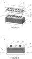
- FIG. 4 illustrates an example of separate compression springs for an active area and a sealant/manifold area.
- FIG. 5 illustrates an embodiment of the compression of an active area.
- FIG. 6 illustrates an embodiment of compression springs on an active area and compression springs on the manifold/sealant area.
- FIGS. 7 A and 7 B illustrate embodiments of complete assembly of fuel cells according to embodiments of the present invention.
- FIG. 8 illustrates an embodiment of compression means for a high temperature fuel cell.
- FIGS. 9 A and 9 B illustrate embodiments of gas supply and manifolds for an assembled fuel cell.
- FIG. 1 represents a conventional and state of the art stack assembly 1 with compression means.
- the assembly forming a fuel cell comprises several cells 2 assembled on top of each other that are encapsulated with two end plates 3 , 4 at the top (plate 3 ) and the bottom (plate 4 ) and with a cover 5 .
- two end plates 3 , 4 at the top (plate 3 ) and the bottom (plate 4 ) and with a cover 5 .
- FIG. 1 A compression with belts 6 (ex. US2006093890A1),
- FIG. 1 B rods 7 and springs (ex. US2002110722A155) and
- FIG. 1 side-panels 8 (ex. JP2012181996A).
- FIG. 2 shows the stack assembly 1 of FIG. 1 in an uncompressed state and exploded view.
- the shape and structure of the integrated compression springs 9 for compression can be different based on the design and application of the fuel cell; however, the main principle in assembly is the same.
- the number of springs 9 and the force applied by the springs are evaluated based on the required pressure on the cells 2 . For example, a pressure between 1 to 2 [MPa] can be applied on the surface of the end plates 3 , 4 .
- Different springs 9 with different compression forces can be used in the centre or on the sides of the assembly if required or according to another distribution.
- the applied pressure on the stack is distributed on the active area of the cell 2 and its surroundings where the manifolds 11 and sealings 12 are located. If it is required to increase the pressure on the sealing/manifold 11 , 12 area for any reason, the external compression kit should be tightened more in that area or thicker sealing materials should be used in order to compress them further and achieve this goal.
- the stack goes through a thermal expansion that often is larger than the expansion of the sealing materials; as a result, it may reduce the compression force on the sealant, which in turn could cause leakages on the long run.
- An aim of the present invention is therefore to improve the known devices and systems.
- a further aim of the present invention is to propose simple and efficient solutions to allow a proper compression of fuel cells, such assemblies and similar products.
- Embodiments of the present invention introduce a new design structure (see FIGS. 3 to 9 for example) that overcomes the issues and problems mentioned above of the known fuel cells.
- the end plates 3 , 4 in embodiments of the present invention are structured so that there is a first separate end plate 20 (“outer or first top end plate”) essentially, and preferably only, in contact with the manifold area 12 and sealant and a second end plate 21 (“inner or second top end plate”) which is preferably surrounded by the first end plate 20 .
- the second end plate 21 is essentially, and preferably only, in contact with the active area 22 of the cell; hence, the current collector 22 .
- the second top end plate may be formed of two plates, attached to each other or not.
- the fuel cell comprises compression springs 23 , 24 that are located on each end plate 20 , 21 separately, springs 23 being on plate 20 and springs 24 on plate 21 .
- This configuration allows the total force to be applied on the manifold (sealant) area 12 and active area 22 to be adjusted based on the number and type of the springs 23 , 24 used in an independent manner.
- the total force on the sealant/manifold area 12 can be adjusted to approximately 2 [MPa] and the total force on the active area 22 can be adjusted to only approximately 1 [MPa] without any interference between the parts (for example the sealant area).
- Springs 23 may all have the same characteristics or they may have different characteristics and the same principle is applicable to springs 24 of the active area. The values indicated are also non-limiting examples.
- the total weight of the assembly can be reduced significantly.
- the top cover 5 and two integrated end plates 20 , 21 can be produced by injection moulding with reinforced plastic, which would be rigid enough to overcome deformation.
- the plate 21 in the middle could be made of a lighter material as it is already encapsulated within an external frame (i.e. plate 20 ).
- Other equivalent and suitable materials are of course possible.
- Another advantage of the current setup according to embodiments of the present invention is that it gives the possibility to adjust the pressure applied on the active area 22 even after a final assembly of the fuel cell.
- FIGS. 5 and 6 An example is shown in FIGS. 5 and 6 : the compression force on the manifold area/sealant 12 and around the active area 22 is achieved by dedicated springs 26 , 27 and top cover 5 and the end plate 21 in the middle is left without any compression means.
- the middle part/end plate 21 several additional compression bolts 25 are added on the top of the end plate 5 .
- the bolts 25 are in direct contact with the end plate 21 in the middle and by tightening them, the compression force applied on the active area 22 of the fuel cell can be increased gradually based on the springs used.
- the total of the force applied can be easily evaluated by the distance the plate 21 moves downwards.
- There are several other means to evaluate the force applied for example, the use of sensors or pressure sensitive films according to embodiments of the present invention or other equivalent means.
- sealant 12 around the active area 22 may need some special treatment for activation; for example, if the sealant is made of a pressure sensitive material then it would be necessary to provide sufficient pressure in order to activate and achieve the best sealing results. This possible and simple to achieve with the principles of the present invention.
- the embodiments of the present invention provide the opportunity to realise this goal without applying any force on the active area 22 .
- the compression in the middle part 21 can be applied similarly to what is shown in FIGS. 5 and 6 .
- the springs 27 that are dedicated for the active area 10 will be compressed based on the force applied by the bolts 25 in the top cover 5 .
- FIG. 7 Another advantage of the embodiments of the present invention is that it can be used with various external compression mechanisms; for example (as illustrated in FIG. 1 ), belts or rods or any other design.
- FIG. 7 An example is shown in FIG. 7 where compression belts 6 hold all the assembly together and the end plate 20 , 21 configurations proposed in embodiments described herein is integrated inside the stack.
- the addition of external bolts 25 on top of the stack is an option and those skilled in the field can judge if they need to have such a flexibility during operation or not, therefore use such bolts or not.
- Another advantage of the embodiments of the present invention is that they can also be used for fuel cells 1 operating at higher temperature such as SOFC (solid oxide fuel cell).
- SOFC solid oxide fuel cell
- a stack can be assembled with compression mechanism similar to FIG. 1 B with external springs, the connections rods can be extended in order to minimise creep and deformation due to high temperature, additional compression bars can be added in the middle of the end plates 21 , 22 in order to compress the active area at different pressure force—an example is shown in FIG. 8 .
- External connection rods would compress the manifolds and sealants of the assembly and connection rods 28 in the middle (single or several) would provide compression on the active area 12 .
- Gas connectors 29 may be positioned on the left or right sides of the bottom end plates for they can be positioned at the bottom of the end plate 4 . also, there is a possibility to integrate them on the top end plate, which is not shown here (ex. US2008311457A1).
Landscapes
- Life Sciences & Earth Sciences (AREA)
- Engineering & Computer Science (AREA)
- Manufacturing & Machinery (AREA)
- Sustainable Development (AREA)
- Sustainable Energy (AREA)
- Chemical & Material Sciences (AREA)
- Chemical Kinetics & Catalysis (AREA)
- Electrochemistry (AREA)
- General Chemical & Material Sciences (AREA)
- Fuel Cell (AREA)
Abstract
Description
Claims (9)
Applications Claiming Priority (3)
| Application Number | Priority Date | Filing Date | Title |
|---|---|---|---|
| CH1462019 | 2019-02-07 | ||
| CH00146/19 | 2019-02-07 | ||
| PCT/IB2020/050962 WO2020161668A1 (en) | 2019-02-07 | 2020-02-06 | Fuel cell stack with compression means |
Publications (2)
| Publication Number | Publication Date |
|---|---|
| US20220115685A1 US20220115685A1 (en) | 2022-04-14 |
| US12261340B2 true US12261340B2 (en) | 2025-03-25 |
Family
ID=69784474
Family Applications (1)
| Application Number | Title | Priority Date | Filing Date |
|---|---|---|---|
| US17/428,689 Active 2040-06-08 US12261340B2 (en) | 2019-02-07 | 2020-02-06 | Fuel cell stack with compression means |
Country Status (8)
| Country | Link |
|---|---|
| US (1) | US12261340B2 (en) |
| EP (1) | EP3921887B1 (en) |
| JP (1) | JP7614104B2 (en) |
| KR (1) | KR20210125042A (en) |
| CN (1) | CN113366681B (en) |
| CA (1) | CA3125890A1 (en) |
| PL (1) | PL3921887T3 (en) |
| WO (1) | WO2020161668A1 (en) |
Families Citing this family (2)
| Publication number | Priority date | Publication date | Assignee | Title |
|---|---|---|---|---|
| US11746427B2 (en) | 2021-07-05 | 2023-09-05 | EvolOH, Inc. | Scalable electrolysis cell and stack and method of high-speed manufacturing the same |
| EP4391126A1 (en) * | 2022-12-24 | 2024-06-26 | Genvia | Compression device for electrochemical cells |
Citations (40)
| Publication number | Priority date | Publication date | Assignee | Title |
|---|---|---|---|---|
| JPH0888018A (en) | 1994-09-16 | 1996-04-02 | Toshiba Corp | Polymer electrolyte fuel cell |
| WO2001056104A2 (en) | 2000-01-27 | 2001-08-02 | Siemens Aktiengesellschaft | Intermediate element for a fuel cell stack and the corresponding fuel cell stack |
| US20020034673A1 (en) | 2000-07-19 | 2002-03-21 | Toyota Jidosha Kabushiki Kaisha | Fuel cell apparatus |
| US20020086199A1 (en) * | 2000-12-22 | 2002-07-04 | Gibb Peter Robert | Compression mechanism for an electrochemical fuel cell assembly |
| US20020110722A1 (en) | 2001-02-15 | 2002-08-15 | Asia Pacific Fuel Cell Technologies, Inc. | Fuel cell with uniform compression device |
| JP2004335336A (en) | 2003-05-09 | 2004-11-25 | Nissan Motor Co Ltd | Fuel cell stack |
| US20050112442A1 (en) * | 2003-11-26 | 2005-05-26 | Wells Allan R. | PEM fuel cell assembly formed of modular sub-assemblies |
| JP2005317388A (en) | 2004-04-28 | 2005-11-10 | Nitta Ind Corp | Manufacturing method of separator |
| EP1601041A1 (en) | 2003-03-06 | 2005-11-30 | Toyota Jidosha Kabushiki Kaisha | Fuel cell |
| US20060046127A1 (en) | 2004-08-27 | 2006-03-02 | Honda Motor Co., Ltd. | Fuel cell stack |
| JP2006114362A (en) | 2004-10-15 | 2006-04-27 | Toyota Motor Corp | Fuel cell |
| US20060093890A1 (en) | 2004-10-29 | 2006-05-04 | Steinbroner Matthew P | Fuel cell stack compression systems, and fuel cell stacks and fuel cell systems incorporating the same |
| US20060115703A1 (en) * | 2004-11-29 | 2006-06-01 | Osamu Kubota | Fuel cell endplate and fuel cell |
| US20060188771A1 (en) | 2005-02-14 | 2006-08-24 | Gencell Corporation | Fuel cell stack compression assembly |
| JP2007005169A (en) | 2005-06-24 | 2007-01-11 | Nissan Motor Co Ltd | Fuel cell stack |
| US20070042250A1 (en) | 2003-11-25 | 2007-02-22 | Toyota Jidosha Kabushiki Kaisha | Fuel cell stack |
| EP1879251A1 (en) | 2006-07-14 | 2008-01-16 | Topsøe Fuel Cell A/S | Compression assembly, solid oxide fuel cell stack, a process for compression of the solid oxide fuel cell stack and its use |
| US20080145713A1 (en) | 2006-12-13 | 2008-06-19 | Connor Eric J | Fuel cell compression retention system using planar strips |
| US20080305380A1 (en) | 2007-06-08 | 2008-12-11 | Benno Andreas-Schott | Fuel cell compression retention system using compliant strapping |
| US20080311457A1 (en) | 2007-06-14 | 2008-12-18 | Benno Andreas-Schott | Fuel cell stack compression retention system using overlapping sheets |
| JP2009152123A (en) | 2007-12-21 | 2009-07-09 | Nissan Motor Co Ltd | Separator, fuel cell stack, and fuel cell stack manufacturing method |
| JP2009158381A (en) | 2007-12-27 | 2009-07-16 | Toyota Motor Corp | Fuel cell stack |
| JP2009187778A (en) | 2008-02-06 | 2009-08-20 | Panasonic Corp | Fuel cell stack and manufacturing method thereof |
| US20090305104A1 (en) | 2007-06-06 | 2009-12-10 | Toshihiro Matsumoto | Polymer electrolyte fuel cell |
| US20090317688A1 (en) | 2006-06-20 | 2009-12-24 | Toshiyuki Inagaki | Fuel cell |
| JP2010198861A (en) | 2009-02-24 | 2010-09-09 | Panasonic Corp | Cell pressing assembly, and fuel battery stack |
| US20110027678A1 (en) * | 2008-04-01 | 2011-02-03 | Daimler Ag | Fuel cell system and method for operating a fuel cell system |
| WO2011123644A2 (en) | 2010-03-31 | 2011-10-06 | Nuvera Fuel Cells, Inc. | Variable load fuel cell |
| JP2012028194A (en) | 2010-07-26 | 2012-02-09 | Honda Motor Co Ltd | Fuel cell stack |
| JP2012181996A (en) | 2011-03-01 | 2012-09-20 | Nissan Motor Co Ltd | Fuel cell stack |
| US20130034790A1 (en) * | 2011-08-05 | 2013-02-07 | Enerfuel, Inc. | Fuel cell stack having a structural heat exchanger |
| WO2013134789A2 (en) | 2012-03-07 | 2013-09-12 | Eveready Battery Company, Inc | Fuel cell stack and compression system therefor |
| GB2509152A (en) | 2012-12-21 | 2014-06-25 | Intelligent Energy Ltd | Fuel Cell Stack Assembly and Method of Assembly |
| WO2016205139A1 (en) | 2015-06-19 | 2016-12-22 | Ballard Power Systems Inc. | Compression apparatus for fuel cell stack |
| US20170025701A1 (en) | 2013-11-26 | 2017-01-26 | University Of Cape Town | A clamp assembly for a fuel cell stack and a method of assembling a fuel cell stack |
| US20170104233A1 (en) | 2015-10-07 | 2017-04-13 | Bloom Energy Corporation | Fuel cell stack column including stress-relief components |
| WO2017131569A1 (en) | 2016-01-27 | 2017-08-03 | Powercell Sweden Ab | Fuel cell stack housing |
| CN107146904A (en) | 2017-04-07 | 2017-09-08 | 上海电气集团股份有限公司 | Fuel cell end plate combination, the combination of distant place end plate, sheet inlet combination and pile |
| CN107275662A (en) | 2016-03-31 | 2017-10-20 | 福特全球技术公司 | Fuel cell pack with take-up device |
| JP2020017416A (en) | 2018-07-26 | 2020-01-30 | 本田技研工業株式会社 | Fuel cell stack |
Family Cites Families (4)
| Publication number | Priority date | Publication date | Assignee | Title |
|---|---|---|---|---|
| CH14619A (en) | 1897-05-04 | 1898-01-15 | De Bruin Franz | Fixed drawing board |
| US20050095485A1 (en) * | 2003-10-31 | 2005-05-05 | 3M Innovative Properties Company | Fuel cell end plate assembly |
| US20080014492A1 (en) * | 2006-07-14 | 2008-01-17 | Jens Ulrick Nielsen | Compression assembly, solid oxide fuel cell stack, a process for compression of the solid oxide fuel cell stack and its use |
| US10256482B2 (en) * | 2016-02-09 | 2019-04-09 | GM Global Technology Operations LLC | Robust fuel cell stack sealing materials and methods using thin elastomeric seals |
-
2020
- 2020-02-06 PL PL20710585.9T patent/PL3921887T3/en unknown
- 2020-02-06 JP JP2021546333A patent/JP7614104B2/en active Active
- 2020-02-06 US US17/428,689 patent/US12261340B2/en active Active
- 2020-02-06 CA CA3125890A patent/CA3125890A1/en active Pending
- 2020-02-06 CN CN202080011224.6A patent/CN113366681B/en active Active
- 2020-02-06 EP EP20710585.9A patent/EP3921887B1/en active Active
- 2020-02-06 WO PCT/IB2020/050962 patent/WO2020161668A1/en not_active Ceased
- 2020-02-06 KR KR1020217028244A patent/KR20210125042A/en active Pending
Patent Citations (45)
| Publication number | Priority date | Publication date | Assignee | Title |
|---|---|---|---|---|
| JPH0888018A (en) | 1994-09-16 | 1996-04-02 | Toshiba Corp | Polymer electrolyte fuel cell |
| WO2001056104A2 (en) | 2000-01-27 | 2001-08-02 | Siemens Aktiengesellschaft | Intermediate element for a fuel cell stack and the corresponding fuel cell stack |
| DE10003528A1 (en) | 2000-01-27 | 2001-08-09 | Siemens Ag | Flexible intermediate element for a fuel cell stack |
| US20020034673A1 (en) | 2000-07-19 | 2002-03-21 | Toyota Jidosha Kabushiki Kaisha | Fuel cell apparatus |
| US20020086199A1 (en) * | 2000-12-22 | 2002-07-04 | Gibb Peter Robert | Compression mechanism for an electrochemical fuel cell assembly |
| US20020110722A1 (en) | 2001-02-15 | 2002-08-15 | Asia Pacific Fuel Cell Technologies, Inc. | Fuel cell with uniform compression device |
| EP1601041A1 (en) | 2003-03-06 | 2005-11-30 | Toyota Jidosha Kabushiki Kaisha | Fuel cell |
| EP2169754A1 (en) | 2003-03-06 | 2010-03-31 | Toyota Jidosha Kabushiki Kaisha | Fuel cell stack |
| JP2004335336A (en) | 2003-05-09 | 2004-11-25 | Nissan Motor Co Ltd | Fuel cell stack |
| US20070042250A1 (en) | 2003-11-25 | 2007-02-22 | Toyota Jidosha Kabushiki Kaisha | Fuel cell stack |
| US20050112442A1 (en) * | 2003-11-26 | 2005-05-26 | Wells Allan R. | PEM fuel cell assembly formed of modular sub-assemblies |
| JP2005317388A (en) | 2004-04-28 | 2005-11-10 | Nitta Ind Corp | Manufacturing method of separator |
| US20060046127A1 (en) | 2004-08-27 | 2006-03-02 | Honda Motor Co., Ltd. | Fuel cell stack |
| JP2006114362A (en) | 2004-10-15 | 2006-04-27 | Toyota Motor Corp | Fuel cell |
| US20060093890A1 (en) | 2004-10-29 | 2006-05-04 | Steinbroner Matthew P | Fuel cell stack compression systems, and fuel cell stacks and fuel cell systems incorporating the same |
| US20060115703A1 (en) * | 2004-11-29 | 2006-06-01 | Osamu Kubota | Fuel cell endplate and fuel cell |
| US20060188771A1 (en) | 2005-02-14 | 2006-08-24 | Gencell Corporation | Fuel cell stack compression assembly |
| JP2007005169A (en) | 2005-06-24 | 2007-01-11 | Nissan Motor Co Ltd | Fuel cell stack |
| US20090317688A1 (en) | 2006-06-20 | 2009-12-24 | Toshiyuki Inagaki | Fuel cell |
| EP1879251A1 (en) | 2006-07-14 | 2008-01-16 | Topsøe Fuel Cell A/S | Compression assembly, solid oxide fuel cell stack, a process for compression of the solid oxide fuel cell stack and its use |
| US20080014489A1 (en) | 2006-07-14 | 2008-01-17 | Jens Ulrik Nielsen | Compression assembly, solid oxide fuel cell stack, a process for compression of the solid oxide fuel cell stack and its use |
| US20080145713A1 (en) | 2006-12-13 | 2008-06-19 | Connor Eric J | Fuel cell compression retention system using planar strips |
| US20090305104A1 (en) | 2007-06-06 | 2009-12-10 | Toshihiro Matsumoto | Polymer electrolyte fuel cell |
| US20080305380A1 (en) | 2007-06-08 | 2008-12-11 | Benno Andreas-Schott | Fuel cell compression retention system using compliant strapping |
| US20080311457A1 (en) | 2007-06-14 | 2008-12-18 | Benno Andreas-Schott | Fuel cell stack compression retention system using overlapping sheets |
| JP2009152123A (en) | 2007-12-21 | 2009-07-09 | Nissan Motor Co Ltd | Separator, fuel cell stack, and fuel cell stack manufacturing method |
| JP2009158381A (en) | 2007-12-27 | 2009-07-16 | Toyota Motor Corp | Fuel cell stack |
| JP2009187778A (en) | 2008-02-06 | 2009-08-20 | Panasonic Corp | Fuel cell stack and manufacturing method thereof |
| US20110027678A1 (en) * | 2008-04-01 | 2011-02-03 | Daimler Ag | Fuel cell system and method for operating a fuel cell system |
| JP2010198861A (en) | 2009-02-24 | 2010-09-09 | Panasonic Corp | Cell pressing assembly, and fuel battery stack |
| WO2011123644A2 (en) | 2010-03-31 | 2011-10-06 | Nuvera Fuel Cells, Inc. | Variable load fuel cell |
| US20110250520A1 (en) * | 2010-03-31 | 2011-10-13 | Nuvera Fuel Cells, Inc. | Variable load fuel cell |
| JP2012028194A (en) | 2010-07-26 | 2012-02-09 | Honda Motor Co Ltd | Fuel cell stack |
| JP2012181996A (en) | 2011-03-01 | 2012-09-20 | Nissan Motor Co Ltd | Fuel cell stack |
| US20130034790A1 (en) * | 2011-08-05 | 2013-02-07 | Enerfuel, Inc. | Fuel cell stack having a structural heat exchanger |
| WO2013134789A2 (en) | 2012-03-07 | 2013-09-12 | Eveready Battery Company, Inc | Fuel cell stack and compression system therefor |
| GB2509152A (en) | 2012-12-21 | 2014-06-25 | Intelligent Energy Ltd | Fuel Cell Stack Assembly and Method of Assembly |
| US20170025701A1 (en) | 2013-11-26 | 2017-01-26 | University Of Cape Town | A clamp assembly for a fuel cell stack and a method of assembling a fuel cell stack |
| WO2016205139A1 (en) | 2015-06-19 | 2016-12-22 | Ballard Power Systems Inc. | Compression apparatus for fuel cell stack |
| US20180316039A1 (en) | 2015-06-19 | 2018-11-01 | Ballard Power Systems Inc. | Compression apparatus for fuel cell stack |
| US20170104233A1 (en) | 2015-10-07 | 2017-04-13 | Bloom Energy Corporation | Fuel cell stack column including stress-relief components |
| WO2017131569A1 (en) | 2016-01-27 | 2017-08-03 | Powercell Sweden Ab | Fuel cell stack housing |
| CN107275662A (en) | 2016-03-31 | 2017-10-20 | 福特全球技术公司 | Fuel cell pack with take-up device |
| CN107146904A (en) | 2017-04-07 | 2017-09-08 | 上海电气集团股份有限公司 | Fuel cell end plate combination, the combination of distant place end plate, sheet inlet combination and pile |
| JP2020017416A (en) | 2018-07-26 | 2020-01-30 | 本田技研工業株式会社 | Fuel cell stack |
Non-Patent Citations (3)
| Title |
|---|
| International Search Report for PCT/IB2020/050962 dated May 6, 2020. |
| Notice of Opposition filed Aug. 7, 2024 in corresponding EP application 20710585. |
| Written Opinion for PCT/IB2020/050962 dated May 6, 2020. |
Also Published As
| Publication number | Publication date |
|---|---|
| US20220115685A1 (en) | 2022-04-14 |
| EP3921887B1 (en) | 2023-11-22 |
| EP3921887C0 (en) | 2023-11-22 |
| JP7614104B2 (en) | 2025-01-15 |
| CN113366681B (en) | 2024-03-08 |
| PL3921887T3 (en) | 2024-03-25 |
| CN113366681A (en) | 2021-09-07 |
| JP2022519735A (en) | 2022-03-24 |
| CA3125890A1 (en) | 2020-08-13 |
| EP3921887A1 (en) | 2021-12-15 |
| WO2020161668A1 (en) | 2020-08-13 |
| KR20210125042A (en) | 2021-10-15 |
Similar Documents
| Publication | Publication Date | Title |
|---|---|---|
| JP5727453B2 (en) | Compression assembly for a fuel cell or electrolyte cell in a fuel cell stack or electrolyte cell stack | |
| EP2058883B1 (en) | Polymer electrolyte fuel cell and electrode/film/frame assembly manufacturing method | |
| CN105261777B (en) | Fuel cell unit and its assemble method | |
| CN103401011B (en) | proton exchange membrane fuel cell stack and fuel cell stack module | |
| US7052796B2 (en) | Externally manifolded membrane based electrochemical cell stacks | |
| US7977011B2 (en) | Fuel stack structure with an adhesive layer | |
| JP6056964B2 (en) | Fuel cell manufacturing method and manufacturing apparatus | |
| CN102473931B (en) | Polymer fuel cell stack | |
| JP6375522B2 (en) | Manufacturing method of fuel cell module | |
| WO2011158551A1 (en) | Fuel cell | |
| US7914943B2 (en) | Integrated seal for fuel cell assembly and fuel cell stack | |
| US12261340B2 (en) | Fuel cell stack with compression means | |
| JP2010532085A (en) | Fuel cell stack and method | |
| US11024866B2 (en) | Elastomeric cell frame for fuel cell, method of manufacturing same, and unit cell having same | |
| CN114899441A (en) | Hydrogen fuel cell unit and method for manufacturing hydrogen fuel cell stack | |
| JP2014229577A (en) | Separator for fuel cell | |
| JP5178061B2 (en) | Fuel cell | |
| HK40057605A (en) | Fuel cell stack with compression means | |
| HK40057605B (en) | Fuel cell stack with compression means | |
| JP6927309B2 (en) | Fuel cell stack structure and thermal strain absorption method for fuel cell stack | |
| KR20140020557A (en) | Device for tightening fuel cell stack | |
| US10862149B2 (en) | Fuel cell stack and manufacturing method therefor | |
| JPS5975576A (en) | Fuel cell |
Legal Events
| Date | Code | Title | Description |
|---|---|---|---|
| AS | Assignment |
Owner name: EH GROUP ENGINEERING AG, SWITZERLAND Free format text: ASSIGNMENT OF ASSIGNORS INTEREST;ASSIGNORS:MATIAN, MARDIT;CHAINHO, ALEXANDRE;REEL/FRAME:057091/0928 Effective date: 20210709 |
|
| FEPP | Fee payment procedure |
Free format text: ENTITY STATUS SET TO UNDISCOUNTED (ORIGINAL EVENT CODE: BIG.); ENTITY STATUS OF PATENT OWNER: LARGE ENTITY |
|
| STPP | Information on status: patent application and granting procedure in general |
Free format text: DOCKETED NEW CASE - READY FOR EXAMINATION |
|
| AS | Assignment |
Owner name: EH GROUP ENGINEERING SA, SWITZERLAND Free format text: CHANGE OF ADDRESS;ASSIGNOR:EH GROUP ENGINEERING SA;REEL/FRAME:060918/0274 Effective date: 20220329 |
|
| STPP | Information on status: patent application and granting procedure in general |
Free format text: NON FINAL ACTION MAILED |
|
| STPP | Information on status: patent application and granting procedure in general |
Free format text: FINAL REJECTION MAILED |
|
| STPP | Information on status: patent application and granting procedure in general |
Free format text: RESPONSE AFTER FINAL ACTION FORWARDED TO EXAMINER |
|
| STPP | Information on status: patent application and granting procedure in general |
Free format text: ADVISORY ACTION MAILED |
|
| STPP | Information on status: patent application and granting procedure in general |
Free format text: DOCKETED NEW CASE - READY FOR EXAMINATION |
|
| STPP | Information on status: patent application and granting procedure in general |
Free format text: NON FINAL ACTION MAILED |
|
| STPP | Information on status: patent application and granting procedure in general |
Free format text: FINAL REJECTION MAILED |
|
| STPP | Information on status: patent application and granting procedure in general |
Free format text: NOTICE OF ALLOWANCE MAILED -- APPLICATION RECEIVED IN OFFICE OF PUBLICATIONS |
|
| STPP | Information on status: patent application and granting procedure in general |
Free format text: PUBLICATIONS -- ISSUE FEE PAYMENT VERIFIED |
|
| STCF | Information on status: patent grant |
Free format text: PATENTED CASE |