US12241852B2 - Gas sensor and method for producing alkaline earth ferrite - Google Patents
Gas sensor and method for producing alkaline earth ferrite Download PDFInfo
- Publication number
- US12241852B2 US12241852B2 US17/754,126 US202017754126A US12241852B2 US 12241852 B2 US12241852 B2 US 12241852B2 US 202017754126 A US202017754126 A US 202017754126A US 12241852 B2 US12241852 B2 US 12241852B2
- Authority
- US
- United States
- Prior art keywords
- gas
- electrode
- gas sensor
- cafe
- alkaline earth
- Prior art date
- Legal status (The legal status is an assumption and is not a legal conclusion. Google has not performed a legal analysis and makes no representation as to the accuracy of the status listed.)
- Active, expires
Links
Images


Classifications
-
- G—PHYSICS
- G01—MEASURING; TESTING
- G01N—INVESTIGATING OR ANALYSING MATERIALS BY DETERMINING THEIR CHEMICAL OR PHYSICAL PROPERTIES
- G01N27/00—Investigating or analysing materials by the use of electric, electrochemical, or magnetic means
- G01N27/02—Investigating or analysing materials by the use of electric, electrochemical, or magnetic means by investigating impedance
- G01N27/04—Investigating or analysing materials by the use of electric, electrochemical, or magnetic means by investigating impedance by investigating resistance
- G01N27/12—Investigating or analysing materials by the use of electric, electrochemical, or magnetic means by investigating impedance by investigating resistance of a solid body in dependence upon absorption of a fluid; of a solid body in dependence upon reaction with a fluid, for detecting components in the fluid
- G01N27/125—Composition of the body, e.g. the composition of its sensitive layer
- G01N27/127—Composition of the body, e.g. the composition of its sensitive layer comprising nanoparticles
-
- G—PHYSICS
- G01—MEASURING; TESTING
- G01N—INVESTIGATING OR ANALYSING MATERIALS BY DETERMINING THEIR CHEMICAL OR PHYSICAL PROPERTIES
- G01N27/00—Investigating or analysing materials by the use of electric, electrochemical, or magnetic means
- G01N27/02—Investigating or analysing materials by the use of electric, electrochemical, or magnetic means by investigating impedance
- G01N27/04—Investigating or analysing materials by the use of electric, electrochemical, or magnetic means by investigating impedance by investigating resistance
- G01N27/12—Investigating or analysing materials by the use of electric, electrochemical, or magnetic means by investigating impedance by investigating resistance of a solid body in dependence upon absorption of a fluid; of a solid body in dependence upon reaction with a fluid, for detecting components in the fluid
- G01N27/125—Composition of the body, e.g. the composition of its sensitive layer
-
- C—CHEMISTRY; METALLURGY
- C01—INORGANIC CHEMISTRY
- C01G—COMPOUNDS CONTAINING METALS NOT COVERED BY SUBCLASSES C01D OR C01F
- C01G49/00—Compounds of iron
- C01G49/0018—Mixed oxides or hydroxides
- C01G49/0036—Mixed oxides or hydroxides containing one alkaline earth metal, magnesium or lead
-
- C—CHEMISTRY; METALLURGY
- C01—INORGANIC CHEMISTRY
- C01P—INDEXING SCHEME RELATING TO STRUCTURAL AND PHYSICAL ASPECTS OF SOLID INORGANIC COMPOUNDS
- C01P2002/00—Crystal-structural characteristics
- C01P2002/50—Solid solutions
- C01P2002/52—Solid solutions containing elements as dopants
- C01P2002/54—Solid solutions containing elements as dopants one element only
-
- C—CHEMISTRY; METALLURGY
- C01—INORGANIC CHEMISTRY
- C01P—INDEXING SCHEME RELATING TO STRUCTURAL AND PHYSICAL ASPECTS OF SOLID INORGANIC COMPOUNDS
- C01P2006/00—Physical properties of inorganic compounds
- C01P2006/40—Electric properties
Definitions
- the present disclosure relates to a gas sensor and a method for producing alkaline earth ferrite applicable to a gas detection member of a gas sensor.
- a semiconductor containing tin oxide fine particles as a main component is often used as a gas detection member for detecting the gases.
- an object of the present disclosure is to provide a gas sensor using a material capable of exhibiting a gas detection ability for a desired gas without treating a surface of a gas detection material.
- the present inventors focus on a finding that a particle shape of a semiconductor material that constitutes the gas detection member of the gas sensor affects a resistance change between bulk resistance of the particles themselves and grain-boundary resistance among the particles, and complete the present disclosure based on this finding.
- a gas sensor includes: a base material; a first electrode and a second electrode arranged on the base material; and a gas detection member connected to the first electrode and the second electrode, wherein the gas detection member contains flaky particles of alkaline earth ferrite.
- the gas detection member by using flaky particles of alkaline earth ferrite for the gas detection member, grain-boundary resistance between adjacent flaky particles of the alkaline earth ferrite can be reduced. Therefore, internal resistance of the gas detection member becomes relatively large when the flaky particles are used for the gas detection member as compared with a case where fine particles are used for the gas detection member, so that a change in the internal resistance due to adsorption of gas can be easily detected. Accordingly, the gas sensor using the flaky particles in the gas detection member can exhibit a gas detection ability for a desired gas.
- FIG. 1 is a plan view in which a part of a gas detection member of a thick-film gas sensor according to an embodiment of the present disclosure is cut out.
- FIG. 2 is a schematic diagram for illustrating a tubular gas sensor according to an embodiment of the present disclosure.
- FIG. 3 is a schematic diagram schematically illustrating an enlarged region A shown in FIG. 1 .
- FIG. 4 is a cross-sectional view taken along a line IV-IV of FIG. 1 .
- FIG. 5 is a schematic diagram for enlarging and illustrating a main part of a general gas sensor.
- FIG. 6 is a schematic diagram for illustrating a resistance component of the gas sensor.
- FIG. 7 is a schematic diagram for explaining a mechanism by which CO 2 gas is detected in alkaline earth ferrite.
- FIG. 8 is a schematic diagram for explaining a mechanism by which CO gas is detected in alkaline earth ferrite.
- FIG. 9 is a schematic diagram for explaining a mechanism by which NO 2 gas is detected in alkaline earth ferrite.
- FIG. 10 is a schematic diagram for explaining CO 2 gas detection of a sensor using flaky particles.
- FIG. 11 is a diagram for illustrating a method for manufacturing a gas detection member containing a flaky element according to the present embodiment.
- FIG. 12 is a circuit diagram for illustrating an evaluation circuit for evaluating performance of the gas sensor.
- FIG. 13 is a diagram illustrating an SEM image of a test piece 4 (CaFe 2 O 4 ).
- FIG. 14 is a diagram illustrating an SEM image of a test piece 5 (CaFe 2 O 4 with Si added) magnified 50,000 times.
- FIG. 15 is a diagram illustrating an SEM image of a test piece 6 (CaFe 2 O 4 with Ti added) magnified 50,000 times.
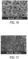
- FIG. 16 is a diagram illustrating an SEM image of a test piece 7 (CaFe 2 O 4 with Zr added) magnified 50,000 times.
- FIG. 17 is a diagram illustrating an SEM image of a test piece 8 (CaFe 2 O 4 with Hf added) magnified 50,000 times.
- FIG. 18 is a diagram illustrating an SEM image of a test piece 9 (CaFe 2 O 4 with 3 mol % of Zr added) magnified 20,000 times.
- FIG. 19 is a diagram illustrating an SEM image of a test piece 10 (CaFe 2 O 4 with 5 mol % of Zr added) magnified 20,000 times.
- FIG. 20 is a diagram illustrating an SEM image of a test piece 11 (CaFe 2 O 4 with 7 mol % of Zr added) magnified 20,000 times.
- FIG. 21 is a diagram illustrating an SEM image of a test piece 12 (CaFe 2 O 4 with 10 mol % of Zr added) magnified 20,000 times.
- FIG. 22 is a diagram illustrating the SEM image of the test piece 10 (CaFe 2 O 4 with 5 mol % of Zr added) magnified 1,000 times.
- FIG. 23 is a diagram illustrating the SEM image of the test piece 10 (CaFe 2 O 4 with 5 mol % of Zr added) magnified 2,500 times.
- FIG. 25 A is an SEM image of a surface of a test piece 13 obtained by performing heating, which corresponds to a second calcination process, for 12 hours and under a temperature of 600° C.
- FIG. 25 B is an SEM image of a surface of a test piece 14 obtained by performing heating, which corresponds to the second calcination process, for 12 hours and under a temperature of 700° C.
- FIG. 25 C is an SEM image of a surface of a test piece 15 obtained by performing heating, which corresponds to the second calcination process, for 12 hours and under a temperature of 800° C.
- FIG. 25 D is an SEM image of a surface of a test piece 16 obtained by performing heating, which corresponds to the second calcination process, for 12 hours and under a temperature of 900° C.
- FIG. 26 is a diagram illustrating gas detection performance of test pieces 1 to 3 .
- FIG. 27 is a diagram illustrating gas detection performance of the test pieces 4 to 8 .
- FIG. 28 is a diagram illustrating gas detection performance of the test pieces 9 to 12 .
- FIG. 29 is a diagram illustrating gas detection performance of the test piece 9 and a test piece 17 .
- FIG. 30 is a diagram illustrating CO 2 gas detection performance in the tubular gas sensor and the thick-film gas sensor.
- FIG. 31 is a diagram illustrating detection performance of CaFe 2 O 4 for CO 2 , CO and NO 2 .
- FIG. 32 is a diagram illustrating the detection performance of CaFe 2 O 4 for CO 2 , CO and NO 2 .
- FIG. 1 is a plan view in which a part of a gas detection member 14 of the gas sensor 10 according to the embodiment of the present disclosure is cut out.
- the gas sensor 10 shown in FIG. 1 includes a base material 11 , a first electrode 12 , a second electrode 13 , and the gas detection member 14 , and these parts constitute a thick-film sensor formed on the flat plate-shaped base material 11 .
- an insulating material or a semi-insulating material can be used as the base material 11 .
- the insulating material structural ceramics such as alumina, silicon dioxide, mullite, magnesium oxide, or forsterite, or glass, or sapphire, or the like can be used.
- the semi-insulating material silicon carbide or the like can be used.
- any material normally used as a base material for a gas sensor can be used as the base material 11 .
- the base material 11 may have a thickness of 0.05 mm or more and 1.0 mm or less. From the viewpoint of strength of the base material 11 , the thickness of the base material 11 is preferably 0.09 mm or more. From the viewpoint of heat dissipation, the thickness of the base material 11 is preferably 1.0 mm or less.
- any material usually used as an electrode or a lead wire can be used as the first electrode 12 and the second electrode 13 .
- a conductive material Cu, Al, Ag, Au, Pt, Ni, Cr, or Sn, or the like can be preferably used.
- the first electrode 12 and the second electrode 13 both can be formed in a comb teeth shape.
- the first electrode 12 and the second electrode 13 are arranged such that on a surface of the base material 11 , each of comb teeth 13 a constituting the second electrode 13 is alternately disposed between each two of comb teeth 12 a constituting the first electrode 12 .
- the first electrode 12 and the second electrode 13 can be formed on the surface of the base material 11 by pattern film formation using a sputtering method, an ion plating method, a vacuum deposition method, or a laser ablation method, or the like, depending on a metal element used.
- the first electrode 12 and the second electrode 13 can be formed by printing an electrode material on the surface of the base material 11 .
- a connecting method such as wire bonding can also be used.
- the first electrode 12 and the second electrode 13 may have a thickness of 0.05 ⁇ m or more and 20 ⁇ m or less. From the viewpoint of detection performance for gas to be detected, the thickness is preferably 1 ⁇ m or more, and from the viewpoint of cost, the thickness is preferably 10 ⁇ m or less.
- a distance between electrodes of the comb tooth 12 a of the first electrode 12 and the comb tooth 13 a of the second electrode 13 is 80 ⁇ m or more and 200 ⁇ m or less.
- a ratio of S to L0 may be 0.27 or more and 4.00 or less. From the viewpoint of sensor characteristics, the ratio is preferably 0.80 or more and 2.00 or less.
- the gas detection member 14 is arranged so as to electrically connect the first electrode 12 to the second electrode 13 .
- the gas detection member 14 is made of a material capable of electrically adsorbing gas molecules to be detected, and detects the gas molecules by utilizing a change in a resistance value accompanying the adsorption of the gas molecules.
- alkaline earth ferrite is used as the material constituting the gas detection member 14 .
- the gas detection member 14 can be manufactured by forming a paste of the alkaline earth ferrite constituting the gas detection member 14 using a binder and applying the paste to the base material 11 by using a screen printing method or the like.
- the paste may be mixed with an insulating material such as glass.
- the gas detection member 14 is formed by coating a region having a predetermined length L1 and a width W1 so as to cover spaces between the comb teeth of the first electrode 12 and the second electrode 13 .
- the sensor characteristics are considered to be the best under a case of less overlap of flaky particles in a thickness direction and ensured conduction between the first electrode 12 and the second electrode 13 .
- the gas detection member 14 may have a thickness of 0.05 ⁇ m or more and 10 ⁇ m or less.
- a predetermined area spanning the first electrode 12 and the second electrode 13 or only a space between the first electrode 12 and the second electrode 13 may be coated with the gas detection member 14 .
- an insulating layer may be arranged on the surface of the base material 11 , and the first electrode 12 and the second electrode 13 may be arranged on the surface of the insulating layer.
- a length L2, and a width W2 of the gas sensor 10 can be appropriately set to a size according to a usage environment of the gas sensor 10 .
- the gas sensor according to the present embodiment can also be configured as a tubular body.
- FIG. 2 is a schematic diagram illustrating a tubular gas sensor 50 .
- FIG. 2 describes a part cut out in order to make a configuration of the tubular gas sensor 50 easy to understand.
- the base material 51 is formed into a tubular shape having a predetermined diameter
- electrodes 52 and 53 are connected to the tubular base material 51 at a predetermined interval
- a material layer 54 constituting a gas detection member is formed around the tubular base material 51 .
- an alumina tube can be used as the base material 51
- platinum wires can be used as the electrodes 52 and 53 .
- the tubular gas sensor 50 can be manufactured by connecting the platinum wires to the alumina tube and then applying the material layer 54 made of alkaline earth ferrite around the alumina tube and the platinum wires.
- the gas sensor 10 is used together with a heater that heats the gas sensor 10 to a detection temperature of a gas to be detected.
- the heater may be integrally formed with the base material 11 of the gas sensor 10 .
- FIG. 3 is a schematic diagram schematically illustrating an enlarged region A shown in FIG. 1 .
- FIG. 4 is a cross-sectional view taken along a line IV-IV of FIG. 1 .
- the gas detection member 14 is made of flaky particles of alkaline earth ferrite.
- a flaky shape means a plate shape having a wide surface and a thickness remarkably small with respect to an expanding direction.
- the gas detection member 14 is formed by aggregating flaky particles 141 of alkaline earth ferrite. Void portions 142 are formed in gaps between the flaky particles 141 .
- some of the flaky particles 141 on the comb teeth 12 a and 13 a are omitted.
- a ratio (M/D) of M to D may be 1 or more and 20 or less.
- the length M of the flaky particle 141 preferably satisfies M ⁇ (2L+2S). It means that one flaky particle 141 does not span three or more comb teeth 12 a (or 13 a ).
- each of the flaky particles 141 has a three-dimensional porous structure in which void portions made of fine pores and a continuous portion are continuous in a thickness direction.
- a total capacity of the fine pores in the flaky particles 141 is preferably 80 cm 3 /g or more, and an average pore diameter of the fine pores is preferably 10 nm or more and 100 nm or less.
- alkaline earth metals it is preferable to use Mg or Ca because of low procurement cost and environmental burden. From the viewpoint of improving gas detection sensitivity, it is more preferable to use Ca.
- the alkaline earth ferrite preferably contains at least one dissimilar element selected from the group consisting of La, Sm, Si, Ti, Hf, and Zr.
- the above-mentioned dissimilar elements it is preferable to use Zr since it is easy to obtain the desired fine pores.
- a content of the dissimilar element may be more than 0 mol % and 10 mol % or less, and is preferably 3 mol % or more and 7 mol % or less.
- the content of the dissimilar element exceeds 10 mol %, the fine pores become difficult to form in the flaky particles 141 .
- the gas detection member 14 having good gas detection sensitivity can be manufactured.
- FIG. 5 is a schematic diagram for enlarging and illustrating a main part of a general gas sensor 100 .
- FIG. 6 is a schematic diagram for illustrating a resistance component of the gas sensor.
- FIG. 5 illustrates the gas sensor 100 including a first electrode 111 and a second electrode 112 arranged on a base material 110 , and a gas detection member 113 electrically connected to the first electrode 111 and the second electrode 112 .
- fine particles 114 on the first electrode 111 and the second electrode 112 are omitted.
- the resistance component generated inside the alkaline earth ferrite constituting the gas detection member of the gas sensor includes three components shown in FIG. 6 .
- a total resistance (R all ) of the gas detection member can be expressed by the sum of the bulk resistance (R b ), the grain-boundary resistance (R gb ), and the electrode interface resistance (R e ).
- FIG. 7 is a schematic diagram for explaining a mechanism by which CO 2 gas is detected in alkaline earth ferrite.
- the gas to be detected is an acid gas such as CO 2
- CO 2 exhibits Lewis acidity, it is considered that CO 2 strongly interacts with a surface of the alkaline earth ferrite.
- CaFe 2 O 4 as the alkaline earth ferrite, it is possible to form the gas detection member 14 that strongly interacts with the acid gas.
- the gas detection sensitivity is defined by an electric resistance change rate ( ⁇ R) or an electric resistance ratio (S), it is easier to read an electric signal when the electric resistance decreases than when the electric resistance increases due to gas adsorption. Therefore, it is considered that the gas detection sensitivity can be increased.
- FIG. 8 is a schematic diagram for explaining responsiveness of the alkaline earth ferrite to CO gas.
- reaction between CO and oxygen (O ⁇ ) adsorbed as negative charges is considered to cause a decrease in the Hall concentration as expressed by the following formula.
- FIG. 9 is a schematic diagram for explaining responsiveness of the alkaline earth ferrite to NO 2 gas. As shown in FIG. 9 , it is considered that interstitial oxygen (O o ) on the surface of the alkaline earth ferrite is involved in the responsiveness to NO 2 .
- interstitial oxygen (O o ) on the surface of the alkaline earth ferrite is involved in the responsiveness to NO 2 .
- Gases such as CO 2 , CO, and NO 2 can be detected by causing the resistance value to change as described above in CaFe 2 O 4 due to adsorption of the gases.
- the electric resistance change rate ( ⁇ R) and the electric resistance ratio (S) can be treated equally with each other, but in general, when the electric resistance change rate ( ⁇ R) is two digits or more, the gas detection sensitivity may be expressed using the electric resistance ratio (S).
- the electric resistance ratio (S) is used to represent the gas detection sensitivity.
- FIG. 10 is a schematic diagram for explaining CO 2 gas detection of a sensor using flaky particles.
- An electric resistance change rate of CO 2 gas ( ⁇ R CO2 ) can be calculated from the grain-boundary resistance R gb and the bulk resistance (R b ).
- the general gas sensor 100 and the gas sensor 10 according to the present embodiment are manufactured under the same electrode material, electrode line width, electrode thickness, and distance between electrodes, in the gas sensor 10 , it is considered that the electric resistance change (bulk resistance) of the alkaline earth ferrite is easy to appear in the resistance change during adsorption of the gas to be detected.
- the method for producing the alkaline earth ferrite according to the present embodiment includes: a step of preparing a mixed solution of a plurality of kinds of metal ions, which is a starting material; a step of adding an organic acid to the obtained mixed solution to prepare a precursor solution containing a metal-organic acid complex; a step of evaporating and drying the precursor solution to obtain a precursor; a step of performing a first calcination process on the precursor; and a step of performing a second calcination process after the first calcination process.
- the method includes a step of adding the dissimilar element to the mixed solution in the form of a metal salt or an alkoxide.
- the starting material may be any material that can dissolve the metal ions, and may be a nitrate such as magnesium (II) nitrate, calcium (II) nitrate, and iron (III) nitrate, a carbonate, or a metal oxide.
- magnesium (II) nitrate and iron (III) nitrate are dissolved in a solvent described later to prepare the mixed solution.
- calcium (II) nitrate and iron (III) nitrate are dissolved in a solvent to prepare the mixed solution.
- deionized water or an organic solvent such as methanol, ethanol, acetylacetone, or ethylene glycol can be used as the solvent for the mixed solution of a plurality of kinds of metal ions as the starting material.
- the organic acid equal to a total number of moles of the metal ions is added to the mixed solution obtained as described above.
- the organic acid malic acid, malonic acid, and the like can be preferably used as long as the organic acid can form a stable chelate complex with the plurality of kinds of metal ions. It is preferable to use malic acid from the viewpoint of flaking and coarsening the alkaline earth ferrite particles obtained in the subsequent step.
- the alkaline earth ferrite contains a dissimilar element
- at least one can be selected from the group consisting of Sm, La, Si, Ti, Hf, and Zr as the dissimilar element.
- These dissimilar elements can be introduced into the alkaline earth ferrite by mixing with the above mixed solution in the form of a metal nitrate or an alkoxide.
- Sm or La When Sm or La is added, it is preferable to use a metal nitrate of Sm or La.
- Si, Ti, Hf, or Zr When Si, Ti, Hf, or Zr is added, it is preferable to use alkoxides thereof.
- tetraethyl orthosilicate can be used as an alkoxide of silicon (Si)
- titanium isopropoxide can be used as an alkoxide of titanium (Ti)
- hafnium ethoxide can be used as an alkoxide of hafnium (Hf).
- an adding amount of the dissimilar element is preferably 10 mol % or less, and more preferably 3 mol % or more and 7 mol % or less, in terms of mole fraction with respect to a total number of moles of the alkaline earth ferrite.
- the obtained precursor is subjected to the first calcination process.
- the first calcination process is a process for removing residual organic substances such as carbonic acid, nitric acid, malic acid, and ethanol in a reaction system, and a temperature of the first calcination process can be set to a temperature higher than a thermal decomposition temperature of the organic acid. From this point, in the present embodiment, the temperature of the first calcination process is 300° C. or higher and 600° C. or lower for 10 minutes or longer and 120 minutes or shorter.
- the second calcination process is performed.
- the second calcination process from the viewpoint of obtaining high-purity alkaline earth ferrite and forming a porous surface of the alkaline earth ferrite, the second calcination process is performed at 600° C. or higher and 1400° C. or lower for 1 hour or longer and 24 hours or shorter.
- FIG. 11 is a diagram for explaining the method for producing the alkaline earth ferrite according to the present embodiment.
- a solution prepared by dissolving a starting material consisting of nitrates 1 - a and 1 - b of Ca and Fe and an alkoxide 1 - c of Zr in ethanol at a stoichiometric ratio is used as a mixed solution 2 , and malic acid 3 is added to the mixed solution 2 and Zr is added as a dissimilar element to prepare a metal-malic acid complex 4 .
- the solution 4 is evaporated and dried to produce a precursor solid 5 .
- the solution 4 containing the metal-organic acid complex is held at a temperature of 80° C. to 120° C. for 1 hour for dehydration or deethanolation. Then, the solution 4 is heated at a temperature of 180° C. to 220° C. for 3 hours. In this way, thermal decomposition of nitrate can be promoted. Subsequently, heat treatment is performed under a temperature of 300° C. to 500° C. for 30 minutes in atmosphere to remove the residual organic substances. Further, the obtained precursor solid 5 is pulverized into a powder to obtain CaFe 2 O 4 powder 6 .
- the shape of the base material 11 of the gas sensor 10 is not limited to that shown in FIG. 1 or FIG. 2 .
- the shapes of the comb teeth 12 a and 13 a and the shape of a lead portion from the comb teeth are not limited to those shown in FIG. 1 .
- a gas sensor according to the embodiment of the present disclosure was manufactured, and gas detection performance and the like of the manufactured gas sensor were measured.
- a method for manufacturing a test piece and evaluation thereof will be described.
- Test Piece 1 Production of MgFe 2 O 4
- Magnesium (III) nitrate and iron (III) nitrate are used as a starting material. These nitrates were dissolved in deionized water, and malic acid equal to a total number of moles of metal ions was added to prepare a metal-organic acid complex solution. The solution was evaporated and dried to obtain a precursor powder. The obtained precursor powder was subjected to a first calcination process in air at 400° C. for 2 hours. Then, a second calcination process was performed at 800° C. for 2 hours. As a result, MgFe 2 O 4 applicable to a gas detection member of the test piece was obtained.
- Test Piece 2 Production of MgFe 2 O 4 with La Added
- a nitrate of lanthanum (La) was used as a metal source for a dissimilar metal to be added.
- Lanthanum nitrate was prepared so that an adding amount of La was 5 mol % with respect to MgFe 2 O 4 , and magnesium (III) nitrate, iron (III) nitrate, and lanthanum nitrate were dissolved in deionized water.
- Malic acid equal to a total number of moles of metal ions was added to prepare a metal-organic acid complex solution. The solution was evaporated and dried in the same manner as for the test piece 1 to obtain a precursor powder. The same calcination process as for the test piece 1 was performed to obtain MgFe 2 O 4 with La added.
- Test Piece 3 Production of MgFe 2 O 4 with Sm Added
- Samarium (Sm) was used as a dissimilar metal to be added.
- Samarium nitrate was prepared so that an adding amount of Sm was 5 mol % with respect to MgFe 2 O 4 , and a metal-organic acid complex solution was prepared in the same manner as for the test piece 2 .
- MgFe 2 O 4 with Sm added was obtained.
- Test Piece 4 Production of CaFe 2 O 4
- CaFe 2 O 4 applicable to a gas detection member of a test piece 4 was obtained by the same operations as for the test piece 1 except that calcium (III) nitrate and iron (III) nitrate were used as the starting material, the first calcination process was performed at 400° C. for 2 hours, and then the second calcination process was performed at 700° C. for 12 hours.
- Test Piece 5 Production of CaFe 2 O 4 with Si Added
- Silicon (Si) was used as a dissimilar metal to be added.
- An alkoxide of Si tetraethyl orthosilicate
- Si tetraethyl orthosilicate
- an adding amount of Si was 5 mol % with respect to CaFe 2 O 4
- calcium (III) nitrate and iron (III) nitrate was obtained.
- Test Piece 6 Production of CaFe 2 O 4 with Ti Added
- Titanium (Ti) was used as a dissimilar metal to be added.
- An alkoxide of Ti titanium isopropoxide
- Ti titanium isopropoxide
- an adding amount of Ti was 5 mol % with respect to CaFe 2 O 4
- calcium (III) nitrate and iron (III) nitrate was obtained.
- Zirconium (Zr) was used as a dissimilar metal to be added.
- An alkoxide of Zr was prepared so that an adding amount of Zr was 5 mol % with respect to CaFe 2 O 4 , and mixed with calcium (III) nitrate and iron (III) nitrate.
- Conditions of the first calcination process and the second calcination process were the same as those for the test piece 4 , and CaFe 2 O 4 with Zr added was obtained.
- Test Piece 8 Production of CaFe 2 O 4 with Hf Added
- Hafnium (Hf) was used as a dissimilar metal to be added.
- An alkoxide of Hf (hafnium ethoxide) was prepared so that an adding amount of Hf was 5 mol % with respect to CaFe 2 O 4 , and mixed with calcium (III) nitrate and iron (III) nitrate.
- Conditions of the first calcination process and the second calcination process were the same as those for the test piece 4 , and CaFe 2 O 4 with Hf added was obtained.
- each nitrate of Ca and Fe and Zr alkoxide were prepared so that a composition of the sensor detection material was CaFe 2-x Zr x O 4 .
- Test Piece 9 CaFe 2 O 4 with 3 mol % of Zr Added
- calcium (II) nitrate tetrahydrate (Ca(NO 3 ) 2 .4H 2 O (purity 99%)), iron (III) nitrate nonahydrate (Fe(NO 3 ) 3 .9H 2 O (purity 99%)), and Zr butoxide (Zirconium (IV) butoxide (85% 1-butanol solution)) were used as the starting material.
- the starting material was prepared at a molar ratio of calcium nitrate, iron nitrate, Zr alkoxide and organic acid (malic acid) of 1:2 to 0.06:0.06:3, and these components were mixed to obtain a metal-organic acid complex solution. Subsequently, the solution was evaporated and dried to obtain a precursor solid. The obtained precursor solid was pulverized and heat-treated at 700° C. for 12 hours in atmosphere to obtain a substance having a composition formula of CaFe 1.84 Zr 0.06 O 4 .
- Test Piece 10 CaFe 2 O 4 with 5 mol % of Zr Added
- test piece 9 The same operations as for the test piece 9 were performed to obtain a substance having a composition formula of CaFe 1.90 Zr 0.10 O 4 except that the starting material was prepared at a molar ratio of calcium nitrate, iron nitrate, Zr alkoxide, and organic acid (malic acid) of 1:2 to 0.10:0.10:3.
- Test Piece 11 CaFe 2 O 4 with 7 mol % of Zr Added
- test piece 9 The same operations as for the test piece 9 were performed to obtain a substance having a composition formula of CaFe 1.86 Zr 0.14 O 4 except that the starting material was prepared at a molar ratio of calcium nitrate, iron nitrate, Zr alkoxide, and organic acid (malic acid) of 1:2 to 0.14:0.14:3.
- Test Piece 12 CaFe 2 O 4 with 10 mol % of Zr Added
- test piece 9 The same operations as for the test piece 9 were performed to obtain a substance having a composition formula of CaFe 1.80 Zr 0.20 O 4 except that the starting material was prepared at a molar ratio of calcium nitrate, iron nitrate, Zr alkoxide, and organic acid (malic acid) of 1:2 to 0.20:0.20:3.
- Test Piece 13 CaFe 2 O 4 with 5 mol % of Zr Added
- test piece 10 The same operations as for the test piece 10 were performed except that the heat treatment was performed at 600° C. for 12 hours.
- Test Piece 14 CaFe 2 O 4 with 5 mol % of Zr Added
- the heat treatment was performed at 700° C. for 12 hours. That is, it is the same substance as the test piece 10 .
- Test Piece 15 CaFe 2 O 4 with 5 mol % of Zr Added
- test piece 10 The same operations as for the test piece 10 were performed except that the heat treatment was performed at 800° C. for 12 hours.
- Test Piece 16 CaFe 2 O 4 with 5 mol % of Zr Added
- test piece 10 The same operations as for the test piece 10 were performed except that the heat treatment was performed at 900° C. for 12 hours.
- Test Piece 17 CaFe 2 O 4 by Solid Phase Reaction Method
- CaFe 2 O 4 was prepared by using a solid phase reaction method.
- a plurality of kinds of raw material powders (CaCO 3 , ⁇ -Fe 2 O 3 ) made of the starting material were weighed in a predetermined amount and mixed.
- CaCO 3 having a purity of 99% and ⁇ -Fe 2 O 3 having a purity of 99% were used.
- CaCO 3 and ⁇ -Fe 2 O 3 were mechanically pulverized and mixed, and then heat-treated in atmosphere at 700° C. to 900° C. for 12 hours to obtain CaFe 2 O 4 powder.
- Test Piece 18 Tubular Gas Sensor Using CaFe 2 O 4
- a tubular gas sensor described later was manufactured using the material of the test piece 4 .
- Test Piece 19 Thick-film Gas Sensor Using CaFe 2 O 4
- a thick-film gas sensor described later was manufactured using the material of the test piece 4 .
- Test Piece 20 Thick-film Gas Sensor Using CaFe 2 O 4 with 5 mol % of Zr Added
- a thick-film gas sensor described later was manufactured using the material of the test piece 10 .
- An alumina tube was used as the base material, and platinum (Pt) was used as the electrode material to manufacture the tubular gas sensor illustrated in FIG. 2 .
- An alumina tube having a diameter of 3.0 mm was used, and the distance between the electrodes 52 and 53 was set to 1.0 mm.
- a paste of MgFe 2 O 4 or CaFe 2 O 4 of the test pieces 1 to 8 was prepared using 5 mass % of ethyl cellulose- ⁇ -terpineol as a binder, and the alumina tube was coated with the obtained paste and dried at 600° C. for 2 hours.
- An alumina substrate was used as the base material, and gold (Au) was used as the electrode material to manufacture the thick-film gas sensor illustrated in FIG. 1 .
- the distance S between each of the comb teeth 12 a of the first electrode 12 and each of the comb teeth 13 a of the second electrode 13 was set to 80 ⁇ m, and the electrode line width L0 of the comb teeth 12 a of the first electrode 12 and the comb teeth 13 a of the second electrode 13 was set to 100 ⁇ m.
- the number of the comb teeth on the first electrode 12 and the second electrode 13 was set to 17 . That is, a total number of the comb teeth was 34 , and the number of gaps between the comb teeth 12 a and the comb teeth 13 a was 33 .
- the alumina substrate was dried at 150° C. for 10 minutes and then heat-treated at 600° C. for 2 hours to obtain a gas sensor as a test piece.
- FIG. 12 is a circuit diagram for illustrating an evaluation circuit for evaluating detection performance of the gas sensor. A change in a resistance value of the gas sensor when a predetermined voltage was applied to a circuit in which the obtained gas sensor and an external resistance were connected in series was measured.
- CO 2 detection performance of a gas sensor was evaluated using synthetic dry air or CO 2 diluted with synthetic dry air (gas concentration: 5000 ppm) as a gas to be detected.
- CO 2 was circulated through the gas sensor of the test piece at a flow rate of 0.10 dm 3 /min, and a change in a resistance value was measured.
- a detection temperature was set to 250° C. to 500° C.
- the electric resistance (R air ) of the gas sensor when in the synthetic dry air and the electric resistance (R gas ) of the gas sensor when exposed to the synthetic dry air containing CO 2 , which is the gas to be detected, were measured, and the electric resistance ratio (S), which is a ratio thereof (R air /R gas ), was taken as the gas detection sensitivity. Results are shown in FIGS. 26 to 30 .
- CO detection performance was evaluated in the same manner as the CO 2 evaluation except that carbon monoxide CO (gas concentration: 500 ppm) was used as the gas to be detected. Above results are shown in FIGS. 31 and 32 .
- NO 2 detection performance was evaluated in the same manner as the CO 2 evaluation except that nitrogen dioxide NO 2 (gas concentration: 10 ppm) was used as the gas to be detected.
- FIG. 13 is a diagram illustrating an SEM image of the test piece 4 (CaFe 2 O 4 ).
- FIG. 14 is a diagram illustrating an SEM image of the test piece 5 (CaFe 2 O 4 with Si added).
- FIG. 15 is a diagram illustrating an SEM image of the test piece 6 (CaFe 2 O 4 with Ti added).
- FIG. 16 is a diagram illustrating an SEM image of the test piece 7 (CaFe 2 O 4 with Zr added).
- FIG. 17 is a diagram illustrating an SEM image of the test piece 8 (CaFe 2 O 4 with Hf added).
- CaFe 2 O 4 has a porous structure. It was also found that a surface structure thereof becomes finer by mixing Si, Ti, Zr, or Hf as the dissimilar element with CaFe 2 O 4 . Especially, it was found that when Ti or Hf is added, the surface of CaFe 2 O 4 can be made finer, and when Si or Zr is added, a three-dimensional porous structure is promoted on the surface of CaFe 2 O 4 .
- FIG. 18 is a diagram illustrating an SEM image of the test piece 9 (CaFe 2 O 4 with 3 mol % of Zr added) magnified 20,000 times.
- FIG. 19 is a diagram illustrating an SEM image of the test piece 10 (CaFe 2 O 4 with 5 mol % of Zr added) magnified 20,000 times.
- FIG. 20 is a diagram illustrating an SEM image of the test piece 11 (CaFe 2 O 4 with 7 mol % of Zr added) magnified 20,000 times.
- FIG. 21 is a diagram illustrating an SEM image of the test piece 12 (CaFe 2 O 4 with 10 mol % of Zr added) magnified 20,000 times.
- FIG. 22 is a diagram illustrating an SEM image of the test piece 10 (CaFe 2 O 4 with 5 mol % of Zr added) magnified 1,000 times.
- FIG. 23 is a diagram illustrating an SEM image of the test piece 10 (CaFe 2 O 4 with 5 mol % of Zr added) magnified 2,500 times.
- particles of CaFe 2 O 4 are flaky, and the whole structure is a structure including void portions between the flaky particles, and it was found that each of the flaky particles has a three-dimensional porous structure when viewed further microscopically.
- FIG. 24 is a diagram illustrating an SEM image of the test piece 17 .
- CaFe 2 O 4 obtained by the solid phase reaction method although refinement of CaFe 2 O 4 itself was promoted, the three-dimensional porous structure could not be confirmed on the surface of CaFe 2 O 4 .
- FIG. 25 A is an SEM image of a surface of the test piece 13 obtained when heating corresponding to the second calcination process is performed for 12 hours at 600° C.
- FIG. 25 B is an SEM image of a surface of the test piece 14 obtained when heating corresponding to the second calcination process is performed for 12 hours at 700° C.
- FIG. 25 C is an SEM image of a surface of the test piece 15 obtained when heating corresponding to the second calcination process is performed for 12 hours at 800° C.
- FIG. 25 D is an SEM image of a surface of the test piece 16 obtained when heating corresponding to the second calcination process is performed for 12 hours at 900° C.
- the heating temperature of the second calcination process is preferably 700° C. or higher.
- FIG. 26 is a diagram illustrating the gas detection performance of the test pieces 1 to 3 .
- the gas detection performance was evaluated by the above-mentioned electric resistance ratio (S).
- S electric resistance ratio
- FIG. 26 shows CO 2 gas sensitivity at each temperature of the gas sensor manufactured by using each of the test piece 1 , with no dissimilar element added (MgFe 2 O 4 ), the test piece 2 with 5 mol % of La added, and the test piece 3 with 5 mol % of Sm added.
- MgFe 2 O 4 which is an n-type semiconductor
- S ⁇ 1 the resistance increases after the gas adsorption. That is, it is calculated as S ⁇ 1.
- MgFe 2 O 4 sensor with La or Sm added can detect CO 2 at a lower temperature side as compared with the sensor without addition.
- MgFe 2 O 4 with La added showed maximum sensitivity at 500° C. It was confirmed that the MgFe 2 O 4 sensor exhibits CO 2 gas sensitivity by adding a dissimilar element.
- FIG. 27 is a diagram showing the gas detection performance of the test pieces 4 to 8 .
- the gas detection performance was evaluated by the electric resistance ratio (S).
- S electric resistance ratio
- a tubular gas sensor was used for an evaluation test.
- FIG. 27 shows CO 2 gas sensitivity at each temperature of the gas sensor manufactured by using each of the test pieces of CaFe 2 O 4 with various types of metal elements added.
- CaFe 2 O 4 which is a p-type semiconductor
- the Hall concentration increases, so that the electric resistance decreases after the gas adsorption. That is, it is calculated as S>1.
- the CaFe 2 O 4 sensor with Hf or Zr added showed high CO 2 sensitivity, and particularly showed maximum sensitivity at a measurement temperature of 300° C. to 350° C. It was found that the CaFe 2 O 4 sensor with Zr added provides rapid responsiveness at approximately 350° C.
- the CaFe 2 O 4 sensor with Zr added shows the best CO 2 sensitivity when the adding amount of Zr is 5 mol %, and particularly shows the maximum sensitivity at a measurement temperature of 300° C. to 350° C.
- the gas detection performance of the test piece 17 manufactured by the solid phase reaction method and the test piece 9 which is CaFe 2 O 4 with 5 mol % of Zr added was evaluated.
- CO 2 was used as the gas to be detected, and the gas detection performance was evaluated by the electric resistance ratio (S).
- S electric resistance ratio
- a tubular gas sensor was used for an evaluation test. Results are shown in FIG. 29 .
- FIG. 29 is a diagram illustrating the gas detection performance of the test piece 9 and the test piece 17 . As shown in FIG. 29 , it was found that the CaFe 2 O 4 sensor with Zr added exhibits sensitivity to CO 2 , and has better CO 2 sensitivity than the CaFe 2 O 4 sensor using the test piece 17 manufactured by the solid phase reaction method.
- the CaFe 2 O 4 particles are flaky, and the whole structure is a structure including void portions between the flaky particles. It was found that each of the CaFe 2 O 4 flaky particles has a three-dimensional porous structure when viewed further microscopically. It was found that CaFe 2 O 4 with 5 mol % of Zr added exhibits sensitivity to CO 2 by having such a structure, and has better CO 2 sensitivity than the CaFe 2 O 4 sensor using the test piece 17 manufactured by the solid phase reaction method.
- FIG. 30 is a diagram illustrating the CO 2 gas detection performance in the tubular gas sensor and the thick-film gas sensor.
- the electric resistance ratio (S) was evaluated using CO 2 as the gas to be detected.
- FIG. 30 shows that the thick-film gas sensor has better CO 2 gas detection sensitivity than the tubular gas sensor. Therefore, by configuring the gas sensor in a thick-film shape, the detection performance for the gas to be detected can be further improved.
- the gas detection sensitivity is improved by using a gas detection member made of a resistor material containing flaky particles since the change in electric resistance (bulk resistance) of the alkaline earth ferrite tends to appear in the change in resistance during adsorption of the gas to be detected.
- the detection performance for CO and NO 2 was evaluated using the gas sensor of the test piece 20 , that is, a thick-film gas sensor having a gas detection member made of a resistor material containing CaFe 2 O 4 with 5 mol % of Zr added.
- FIGS. 31 and 32 are diagrams illustrating detection performance for CO 2 , CO, and NO 2 .
- the electric resistance ratio (S) peaks in the vicinity of 350° C. and changes to a value larger than 1 in a temperature range of at least 200° C. to 500° C. This is because, as described with reference to FIG. 7 , CaFe 2 O 4 is a p-type semiconductor and the Hall concentration thereof increases corresponding to the adsorption of CO 2 , so that the electric resistance of CaFe 2 O 4 decreases due to the adsorption of CO 2 .
- the electric resistance ratio (S) peaks in 250° C. and changes in a direction of decreasing by more than 1 in a temperature range of at least 200° C. or less to 400° C. This is because, as described with reference to FIG. 8 , the Hall concentration of CaFe 2 O 4 decreases corresponding to the adsorption of CO, so that the electric resistance of CaFe 2 O 4 increases due to the adsorption of CO.
- the electric resistance ratio (S) peaks in 200° C. and changes in a direction of increasing more than 1 in a temperature range of approximately 450° C. or less. This is because, as described with reference to FIG. 9 , the Hall concentration of CaFe 2 O 4 increases corresponding to the adsorption of NO 2 , the electric resistance of CaFe 2 O 4 decreases due to the adsorption of NO 2 .
- the gas sensor shown as the Example has the detection performance not only for CO 2 but also for CO and NO 2 .
Landscapes
- Chemical & Material Sciences (AREA)
- Life Sciences & Earth Sciences (AREA)
- Organic Chemistry (AREA)
- Analytical Chemistry (AREA)
- Biochemistry (AREA)
- Pathology (AREA)
- Immunology (AREA)
- General Physics & Mathematics (AREA)
- Chemical Kinetics & Catalysis (AREA)
- Electrochemistry (AREA)
- Physics & Mathematics (AREA)
- Health & Medical Sciences (AREA)
- General Health & Medical Sciences (AREA)
- Inorganic Chemistry (AREA)
- General Life Sciences & Earth Sciences (AREA)
- Geology (AREA)
- Nanotechnology (AREA)
- Engineering & Computer Science (AREA)
- Investigating Or Analyzing Materials By The Use Of Fluid Adsorption Or Reactions (AREA)
Abstract
Description
-
- (1) Bulk resistance Rb, which is an internal resistance of the oxide
fine particles 114; - (2) Grain-boundary resistance Rgb between
fine particles 114 in contact with each other; and - (3) Electrode interface resistance Re between the
fine particles 114 and the first electrode 111 (or the second electrode 112).
- (1) Bulk resistance Rb, which is an internal resistance of the oxide
O−+CO2+e−→CO3 2−
O2−+CO2→CO3 2−
M-O− ads+CO→CO2+e−
Oo+NO2+e−→NO3 −
Claims (10)
Applications Claiming Priority (4)
| Application Number | Priority Date | Filing Date | Title |
|---|---|---|---|
| CN2019-173525 | 2019-09-24 | ||
| JP2019-173525 | 2019-09-24 | ||
| JP2019173525A JP7312401B2 (en) | 2019-09-24 | 2019-09-24 | Gas sensor and manufacturing method of alkaline earth ferrite |
| PCT/JP2020/032227 WO2021059839A1 (en) | 2019-09-24 | 2020-08-26 | Gas sensor and alkaline earth ferrite production method |
Publications (2)
| Publication Number | Publication Date |
|---|---|
| US20220291160A1 US20220291160A1 (en) | 2022-09-15 |
| US12241852B2 true US12241852B2 (en) | 2025-03-04 |
Family
ID=75157617
Family Applications (1)
| Application Number | Title | Priority Date | Filing Date |
|---|---|---|---|
| US17/754,126 Active 2040-10-23 US12241852B2 (en) | 2019-09-24 | 2020-08-26 | Gas sensor and method for producing alkaline earth ferrite |
Country Status (5)
| Country | Link |
|---|---|
| US (1) | US12241852B2 (en) |
| JP (1) | JP7312401B2 (en) |
| CN (1) | CN114402194B (en) |
| DE (1) | DE112020004494T5 (en) |
| WO (1) | WO2021059839A1 (en) |
Families Citing this family (1)
| Publication number | Priority date | Publication date | Assignee | Title |
|---|---|---|---|---|
| JP7754419B2 (en) * | 2022-01-18 | 2025-10-15 | 独立行政法人国立高等専門学校機構 | Gas Sensor |
Citations (10)
| Publication number | Priority date | Publication date | Assignee | Title |
|---|---|---|---|---|
| US20040007462A1 (en) * | 2001-12-03 | 2004-01-15 | Yasumichi Hotta | Gas sensor element and its production method |
| US20060044144A1 (en) * | 2004-08-28 | 2006-03-02 | Landon Duval | Substance detection and alarm using a spectrometer built into a steering wheel assembly |
| US20060257288A1 (en) * | 2005-05-03 | 2006-11-16 | Teledyne Technologies Incorporated | Hydrogen sulfide tolerant oxygen gas sensing device |
| US20070071651A1 (en) * | 2005-09-29 | 2007-03-29 | Yasuhiro Kato | Detecting device for hydrogen halide gas and absorbing apparatus for hydrogen halide gas |
| US20080105545A1 (en) * | 2005-08-02 | 2008-05-08 | Ngk Insulators, Ltd. | Gas sensor element |
| US20150061706A1 (en) | 2013-08-27 | 2015-03-05 | Council Of Scientific & Industrial Research | Resistive type humidity sensor based on porous magnesium ferrite pellet |
| US20170167999A1 (en) | 2015-12-11 | 2017-06-15 | Rohm Co., Ltd. | Semiconductor type gas sensor, method of manufacturing semiconductor type gas sensor, and sensor network system |
| US20180106754A1 (en) * | 2015-05-13 | 2018-04-19 | Ngk Spark Plug Co., Ltd. | Electrically conductive oxide sintered compact, member for electrical conduction, and gas sensor |
| US20190079041A1 (en) * | 2017-08-22 | 2019-03-14 | Nutech Ventures | Carbon nanostructure based gas sensors and method of making same |
| US20200003718A1 (en) * | 2017-03-31 | 2020-01-02 | Sensirion Ag | Sensor for measuring a gas concentration |
Family Cites Families (12)
| Publication number | Priority date | Publication date | Assignee | Title |
|---|---|---|---|---|
| JPS5958349A (en) * | 1982-09-28 | 1984-04-04 | Matsushita Electric Ind Co Ltd | gas detection element |
| DE3922747A1 (en) * | 1988-07-25 | 1990-03-08 | Degussa | Doped alkaline earth metal and lead ferrite prodn. |
| FR2660650B1 (en) * | 1990-04-09 | 1993-01-08 | Centre Nat Rech Scient | PROCESS FOR THE PREPARATION OF HEXAFERRITE PARTICLES. |
| US5972296A (en) * | 1995-05-09 | 1999-10-26 | Heraeus Electro-Nite International, N.V. | Oxygen sensors made of alkaline-earth-doped lanthanum ferrites and method of use thereof |
| US7371117B2 (en) | 2004-09-30 | 2008-05-13 | Amphenol Corporation | High speed, high density electrical connector |
| CN104261482B (en) | 2012-11-29 | 2016-03-30 | 江苏理工学院 | Method for preparing ferrite nanospheres by molten salt method |
| WO2014087932A1 (en) * | 2012-12-03 | 2014-06-12 | Tdk株式会社 | METHOD FOR PRODUCING Sr FERRITE SINTERED MAGNET |
| CN104215673A (en) * | 2014-08-28 | 2014-12-17 | 宁波大学 | Preparation method of Zr-based nitric oxide sensor with high selectivity |
| JP2017043808A (en) | 2015-08-27 | 2017-03-02 | 大阪鋼灰株式会社 | Lime-based dephosphorization agent |
| JP6399363B2 (en) * | 2016-05-02 | 2018-10-03 | パウダーテック株式会社 | Ferrite powder, resin composition, electromagnetic shielding material, electronic circuit board, electronic circuit component, and electronic equipment casing |
| JP7022636B2 (en) | 2018-03-30 | 2022-02-18 | 三協立山株式会社 | Simple structure |
| CN110082397B (en) * | 2019-06-03 | 2021-02-05 | 海南大学 | Cobalt tetroxide oxide semiconductor xylene sensor, preparation method and application thereof |
-
2019
- 2019-09-24 JP JP2019173525A patent/JP7312401B2/en active Active
-
2020
- 2020-08-26 DE DE112020004494.7T patent/DE112020004494T5/en active Pending
- 2020-08-26 US US17/754,126 patent/US12241852B2/en active Active
- 2020-08-26 WO PCT/JP2020/032227 patent/WO2021059839A1/en not_active Ceased
- 2020-08-26 CN CN202080065042.7A patent/CN114402194B/en active Active
Patent Citations (11)
| Publication number | Priority date | Publication date | Assignee | Title |
|---|---|---|---|---|
| US20040007462A1 (en) * | 2001-12-03 | 2004-01-15 | Yasumichi Hotta | Gas sensor element and its production method |
| US20060044144A1 (en) * | 2004-08-28 | 2006-03-02 | Landon Duval | Substance detection and alarm using a spectrometer built into a steering wheel assembly |
| US20060257288A1 (en) * | 2005-05-03 | 2006-11-16 | Teledyne Technologies Incorporated | Hydrogen sulfide tolerant oxygen gas sensing device |
| US20080105545A1 (en) * | 2005-08-02 | 2008-05-08 | Ngk Insulators, Ltd. | Gas sensor element |
| US20070071651A1 (en) * | 2005-09-29 | 2007-03-29 | Yasuhiro Kato | Detecting device for hydrogen halide gas and absorbing apparatus for hydrogen halide gas |
| US20150061706A1 (en) | 2013-08-27 | 2015-03-05 | Council Of Scientific & Industrial Research | Resistive type humidity sensor based on porous magnesium ferrite pellet |
| JP2015083530A (en) | 2013-08-27 | 2015-04-30 | カウンシル オブ サイエンティフィック アンド インダストリアル リサーチ | Resistance type humidity sensor based on porous magnesium ferrite pellets |
| US20180106754A1 (en) * | 2015-05-13 | 2018-04-19 | Ngk Spark Plug Co., Ltd. | Electrically conductive oxide sintered compact, member for electrical conduction, and gas sensor |
| US20170167999A1 (en) | 2015-12-11 | 2017-06-15 | Rohm Co., Ltd. | Semiconductor type gas sensor, method of manufacturing semiconductor type gas sensor, and sensor network system |
| US20200003718A1 (en) * | 2017-03-31 | 2020-01-02 | Sensirion Ag | Sensor for measuring a gas concentration |
| US20190079041A1 (en) * | 2017-08-22 | 2019-03-14 | Nutech Ventures | Carbon nanostructure based gas sensors and method of making same |
Non-Patent Citations (4)
| Title |
|---|
| Chemical Sensors, Apr. 5, 2018, vol. 35, Supplement B (2019), Obata Kenji et al., "CO Sensing Properties of Lanthanoid—Added MgFe2O4". |
| Chemical Sensors, Apr. 5, 2018, vol. 35, Supplement B (2019), Obata Kenji et al., "CO2 Sensing Properties of a CaFe2O4 Thick-Film-Type Gas Sensor". |
| Concise Explanation Chemical Sensors, Sep. 5, 2019, vol. 35, Supplement B, 2019, pp. 10-12. Obata, Kenji et al., "CO2 sensing properties of CaFe2O4 Thick-Film-Type Gas Sensor". |
| International Search Report, Application No. PCT/JP2020/032227, mailed Nov. 24, 2020. ISA/Japan Patent Office. |
Also Published As
| Publication number | Publication date |
|---|---|
| WO2021059839A1 (en) | 2021-04-01 |
| JP2021050984A (en) | 2021-04-01 |
| US20220291160A1 (en) | 2022-09-15 |
| CN114402194B (en) | 2024-02-13 |
| DE112020004494T5 (en) | 2022-06-23 |
| JP7312401B2 (en) | 2023-07-21 |
| CN114402194A (en) | 2022-04-26 |
Similar Documents
| Publication | Publication Date | Title |
|---|---|---|
| Illyaskutty et al. | Enhanced ethanol sensing response from nanostructured MoO 3: ZnO thin films and their mechanism of sensing | |
| JP5076377B2 (en) | Exhaust gas purification catalyst | |
| EP2692432B1 (en) | Exhaust gas purification catalyst, exhaust gas purification monolith catalyst, and process for producing exhaust gas purification catalyst | |
| JP6586694B2 (en) | Material for gas sensor, method for producing the same, and method for producing gas sensor using the same | |
| US5389340A (en) | Module and device for detecting NOX gas | |
| EP3608298A1 (en) | Method for manufacturing sintered body, structure, and composite structure | |
| WO2007127373A2 (en) | Base metal electrode multilayer capacitor with localized oxidizing source | |
| JPWO2009054315A1 (en) | Exhaust gas purification catalyst | |
| JP6033127B2 (en) | Nitrogen oxide decomposition material and use thereof | |
| US20180106754A1 (en) | Electrically conductive oxide sintered compact, member for electrical conduction, and gas sensor | |
| US12241852B2 (en) | Gas sensor and method for producing alkaline earth ferrite | |
| JP6710181B2 (en) | Oxygen storage material and manufacturing method thereof | |
| RU2237039C2 (en) | Perovskite-type ceramic material | |
| TWI799569B (en) | solid electrolyte junction | |
| JP7754419B2 (en) | Gas Sensor | |
| Wisser et al. | Preparation and microcontact printing of platinum and palladium thin films | |
| JP2016065827A (en) | Oxygen sensor | |
| JPH08271465A (en) | Ammonia gas sensor and manufacturing method thereof | |
| JP6800127B2 (en) | Oxygen storage material and its manufacturing method | |
| US20190321806A1 (en) | Oxygen storage material and method for producing the same | |
| JP3444347B2 (en) | Oxide ion conductor and method for producing the same | |
| JP2005132644A (en) | Functional porous film and method of manufacturing the same, and sensor | |
| JP2007054685A (en) | Catalyst for water gas shift reaction | |
| JP2004117126A (en) | Hydrocarbon sensor and method of using the same | |
| JPH08271467A (en) | Nitrogen oxide sensor |
Legal Events
| Date | Code | Title | Description |
|---|---|---|---|
| AS | Assignment |
Owner name: KOA CORPORATION, JAPAN Free format text: ASSIGNMENT OF ASSIGNORS INTEREST;ASSIGNORS:MATSUSHIMA, SHIGENORI;OBATA, KENJI;IGUCHI, KENICHI;AND OTHERS;SIGNING DATES FROM 20220228 TO 20220307;REEL/FRAME:059392/0816 Owner name: NATIONAL INSTITUTE OF TECHNOLOGY, JAPAN Free format text: ASSIGNMENT OF ASSIGNORS INTEREST;ASSIGNORS:MATSUSHIMA, SHIGENORI;OBATA, KENJI;IGUCHI, KENICHI;AND OTHERS;SIGNING DATES FROM 20220228 TO 20220307;REEL/FRAME:059392/0816 |
|
| FEPP | Fee payment procedure |
Free format text: ENTITY STATUS SET TO UNDISCOUNTED (ORIGINAL EVENT CODE: BIG.); ENTITY STATUS OF PATENT OWNER: LARGE ENTITY |
|
| STPP | Information on status: patent application and granting procedure in general |
Free format text: DOCKETED NEW CASE - READY FOR EXAMINATION |
|
| STPP | Information on status: patent application and granting procedure in general |
Free format text: NON FINAL ACTION MAILED |
|
| STPP | Information on status: patent application and granting procedure in general |
Free format text: RESPONSE TO NON-FINAL OFFICE ACTION ENTERED AND FORWARDED TO EXAMINER |
|
| STPP | Information on status: patent application and granting procedure in general |
Free format text: NOTICE OF ALLOWANCE MAILED -- APPLICATION RECEIVED IN OFFICE OF PUBLICATIONS |
|
| STPP | Information on status: patent application and granting procedure in general |
Free format text: AWAITING TC RESP., ISSUE FEE NOT PAID |
|
| STPP | Information on status: patent application and granting procedure in general |
Free format text: PUBLICATIONS -- ISSUE FEE PAYMENT VERIFIED |
|
| STCF | Information on status: patent grant |
Free format text: PATENTED CASE |