US12241768B2 - System and a process for monitoring and verifying bunker fuel exchange between marine vessels - Google Patents
System and a process for monitoring and verifying bunker fuel exchange between marine vessels Download PDFInfo
- Publication number
- US12241768B2 US12241768B2 US17/879,684 US202217879684A US12241768B2 US 12241768 B2 US12241768 B2 US 12241768B2 US 202217879684 A US202217879684 A US 202217879684A US 12241768 B2 US12241768 B2 US 12241768B2
- Authority
- US
- United States
- Prior art keywords
- fluid
- marine vessel
- parameters
- computer
- dashboard
- Prior art date
- Legal status (The legal status is an assumption and is not a legal conclusion. Google has not performed a legal analysis and makes no representation as to the accuracy of the status listed.)
- Active
Links
- 238000000034 method Methods 0.000 title claims abstract description 96
- 238000012544 monitoring process Methods 0.000 title claims abstract description 53
- 239000010747 number 6 fuel oil Substances 0.000 title description 22
- 238000012384 transportation and delivery Methods 0.000 claims abstract description 95
- 239000012530 fluid Substances 0.000 claims abstract description 76
- 238000005259 measurement Methods 0.000 claims abstract description 52
- 238000004891 communication Methods 0.000 claims description 39
- 238000004590 computer program Methods 0.000 claims description 17
- 230000033001 locomotion Effects 0.000 claims description 13
- 230000001105 regulatory effect Effects 0.000 claims description 13
- 239000005864 Sulphur Substances 0.000 claims description 9
- 239000000126 substance Substances 0.000 claims description 9
- NINIDFKCEFEMDL-UHFFFAOYSA-N Sulfur Chemical compound [S] NINIDFKCEFEMDL-UHFFFAOYSA-N 0.000 claims description 8
- 230000000704 physical effect Effects 0.000 claims description 6
- 239000013049 sediment Substances 0.000 claims description 3
- XLYOFNOQVPJJNP-UHFFFAOYSA-N water Substances O XLYOFNOQVPJJNP-UHFFFAOYSA-N 0.000 claims description 3
- 238000013481 data capture Methods 0.000 abstract description 18
- 239000000446 fuel Substances 0.000 description 44
- 238000012546 transfer Methods 0.000 description 13
- 239000000295 fuel oil Substances 0.000 description 6
- 238000010295 mobile communication Methods 0.000 description 6
- 239000007788 liquid Substances 0.000 description 5
- 238000005070 sampling Methods 0.000 description 4
- 239000000203 mixture Substances 0.000 description 3
- 238000004458 analytical method Methods 0.000 description 2
- 230000008901 benefit Effects 0.000 description 2
- 238000004364 calculation method Methods 0.000 description 2
- 238000005516 engineering process Methods 0.000 description 2
- 239000010763 heavy fuel oil Substances 0.000 description 2
- 230000004048 modification Effects 0.000 description 2
- 238000012795 verification Methods 0.000 description 2
- 238000005273 aeration Methods 0.000 description 1
- 230000000712 assembly Effects 0.000 description 1
- 238000000429 assembly Methods 0.000 description 1
- 238000012550 audit Methods 0.000 description 1
- 230000002457 bidirectional effect Effects 0.000 description 1
- 230000001413 cellular effect Effects 0.000 description 1
- 238000002485 combustion reaction Methods 0.000 description 1
- 238000012937 correction Methods 0.000 description 1
- 238000013479 data entry Methods 0.000 description 1
- 238000007598 dipping method Methods 0.000 description 1
- 238000005553 drilling Methods 0.000 description 1
- 239000000839 emulsion Substances 0.000 description 1
- 239000002828 fuel tank Substances 0.000 description 1
- 230000002452 interceptive effect Effects 0.000 description 1
- 238000009533 lab test Methods 0.000 description 1
- 239000003949 liquefied natural gas Substances 0.000 description 1
- 238000007726 management method Methods 0.000 description 1
- 239000010759 marine diesel oil Substances 0.000 description 1
- 239000010758 marine gas oil Substances 0.000 description 1
- 238000000691 measurement method Methods 0.000 description 1
- 238000012986 modification Methods 0.000 description 1
- 238000012806 monitoring device Methods 0.000 description 1
- 239000003921 oil Substances 0.000 description 1
- 230000010355 oscillation Effects 0.000 description 1
- 238000012545 processing Methods 0.000 description 1
- 238000005086 pumping Methods 0.000 description 1
- 230000003134 recirculating effect Effects 0.000 description 1
- 239000002002 slurry Substances 0.000 description 1
- 230000002459 sustained effect Effects 0.000 description 1
Images


Classifications
-
- B—PERFORMING OPERATIONS; TRANSPORTING
- B63—SHIPS OR OTHER WATERBORNE VESSELS; RELATED EQUIPMENT
- B63B—SHIPS OR OTHER WATERBORNE VESSELS; EQUIPMENT FOR SHIPPING
- B63B17/00—Vessels parts, details, or accessories, not otherwise provided for
- B63B17/0027—Tanks for fuel or the like ; Accessories therefor, e.g. tank filler caps
- B63B17/0036—Arrangements for minimizing pollution by accidents
-
- B—PERFORMING OPERATIONS; TRANSPORTING
- B63—SHIPS OR OTHER WATERBORNE VESSELS; RELATED EQUIPMENT
- B63B—SHIPS OR OTHER WATERBORNE VESSELS; EQUIPMENT FOR SHIPPING
- B63B27/00—Arrangement of ship-based loading or unloading equipment for cargo or passengers
- B63B27/30—Arrangement of ship-based loading or unloading equipment for transfer at sea between ships or between ships and off-shore structures
- B63B27/34—Arrangement of ship-based loading or unloading equipment for transfer at sea between ships or between ships and off-shore structures using pipe-lines
-
- G—PHYSICS
- G01—MEASURING; TESTING
- G01F—MEASURING VOLUME, VOLUME FLOW, MASS FLOW OR LIQUID LEVEL; METERING BY VOLUME
- G01F1/00—Measuring the volume flow or mass flow of fluid or fluent solid material wherein the fluid passes through a meter in a continuous flow
- G01F1/56—Measuring the volume flow or mass flow of fluid or fluent solid material wherein the fluid passes through a meter in a continuous flow by using electric or magnetic effects
-
- G—PHYSICS
- G01—MEASURING; TESTING
- G01F—MEASURING VOLUME, VOLUME FLOW, MASS FLOW OR LIQUID LEVEL; METERING BY VOLUME
- G01F1/00—Measuring the volume flow or mass flow of fluid or fluent solid material wherein the fluid passes through a meter in a continuous flow
- G01F1/76—Devices for measuring mass flow of a fluid or a fluent solid material
- G01F1/78—Direct mass flowmeters
- G01F1/80—Direct mass flowmeters operating by measuring pressure, force, momentum, or frequency of a fluid flow to which a rotational movement has been imparted
- G01F1/84—Coriolis or gyroscopic mass flowmeters
-
- G—PHYSICS
- G01—MEASURING; TESTING
- G01F—MEASURING VOLUME, VOLUME FLOW, MASS FLOW OR LIQUID LEVEL; METERING BY VOLUME
- G01F15/00—Details of, or accessories for, apparatus of groups G01F1/00 - G01F13/00 insofar as such details or appliances are not adapted to particular types of such apparatus
- G01F15/06—Indicating or recording devices
- G01F15/061—Indicating or recording devices for remote indication
- G01F15/063—Indicating or recording devices for remote indication using electrical means
-
- G—PHYSICS
- G01—MEASURING; TESTING
- G01F—MEASURING VOLUME, VOLUME FLOW, MASS FLOW OR LIQUID LEVEL; METERING BY VOLUME
- G01F15/00—Details of, or accessories for, apparatus of groups G01F1/00 - G01F13/00 insofar as such details or appliances are not adapted to particular types of such apparatus
- G01F15/06—Indicating or recording devices
- G01F15/065—Indicating or recording devices with transmission devices, e.g. mechanical
- G01F15/066—Indicating or recording devices with transmission devices, e.g. mechanical involving magnetic transmission devices
-
- G—PHYSICS
- G01—MEASURING; TESTING
- G01F—MEASURING VOLUME, VOLUME FLOW, MASS FLOW OR LIQUID LEVEL; METERING BY VOLUME
- G01F22/00—Methods or apparatus for measuring volume of fluids or fluent solid material, not otherwise provided for
-
- G—PHYSICS
- G01—MEASURING; TESTING
- G01N—INVESTIGATING OR ANALYSING MATERIALS BY DETERMINING THEIR CHEMICAL OR PHYSICAL PROPERTIES
- G01N9/00—Investigating density or specific gravity of materials; Analysing materials by determining density or specific gravity
- G01N9/32—Investigating density or specific gravity of materials; Analysing materials by determining density or specific gravity by using flow properties of fluids, e.g. flow through tubes or apertures
-
- G—PHYSICS
- G08—SIGNALLING
- G08C—TRANSMISSION SYSTEMS FOR MEASURED VALUES, CONTROL OR SIMILAR SIGNALS
- G08C17/00—Arrangements for transmitting signals characterised by the use of a wireless electrical link
- G08C17/02—Arrangements for transmitting signals characterised by the use of a wireless electrical link using a radio link
-
- G—PHYSICS
- G01—MEASURING; TESTING
- G01F—MEASURING VOLUME, VOLUME FLOW, MASS FLOW OR LIQUID LEVEL; METERING BY VOLUME
- G01F1/00—Measuring the volume flow or mass flow of fluid or fluent solid material wherein the fluid passes through a meter in a continuous flow
- G01F1/76—Devices for measuring mass flow of a fluid or a fluent solid material
- G01F1/78—Direct mass flowmeters
- G01F1/80—Direct mass flowmeters operating by measuring pressure, force, momentum, or frequency of a fluid flow to which a rotational movement has been imparted
- G01F1/84—Coriolis or gyroscopic mass flowmeters
- G01F1/8409—Coriolis or gyroscopic mass flowmeters constructional details
- G01F1/8422—Coriolis or gyroscopic mass flowmeters constructional details exciters
-
- G—PHYSICS
- G01—MEASURING; TESTING
- G01F—MEASURING VOLUME, VOLUME FLOW, MASS FLOW OR LIQUID LEVEL; METERING BY VOLUME
- G01F1/00—Measuring the volume flow or mass flow of fluid or fluent solid material wherein the fluid passes through a meter in a continuous flow
- G01F1/76—Devices for measuring mass flow of a fluid or a fluent solid material
- G01F1/78—Direct mass flowmeters
- G01F1/80—Direct mass flowmeters operating by measuring pressure, force, momentum, or frequency of a fluid flow to which a rotational movement has been imparted
- G01F1/84—Coriolis or gyroscopic mass flowmeters
- G01F1/8409—Coriolis or gyroscopic mass flowmeters constructional details
- G01F1/8427—Coriolis or gyroscopic mass flowmeters constructional details detectors
-
- H—ELECTRICITY
- H04—ELECTRIC COMMUNICATION TECHNIQUE
- H04W—WIRELESS COMMUNICATION NETWORKS
- H04W84/00—Network topologies
- H04W84/02—Hierarchically pre-organised networks, e.g. paging networks, cellular networks, WLAN [Wireless Local Area Network] or WLL [Wireless Local Loop]
- H04W84/10—Small scale networks; Flat hierarchical networks
- H04W84/12—WLAN [Wireless Local Area Networks]
Definitions
- the present disclosure relates generally to a system for measuring an amount of fuel delivered during a bunkering operation between a barge and a vessel. More specifically, the inventive concepts described herein aim to allow such measurements to be reported in real time during the bunkering process and to ensure the authenticity of the measurements being reported.
- Bunkering malpractice is a well-known phenomenon in the shipping industry. Unscrupulous parties stand to make substantial profits through misreporting on the quality and/or the quantity of fuel delivered from a bunker supply ship (barge) to a bunker receiving vessel during bunkering processes.
- Bunker fuel can mean any distillate or residual fuel intended for combustion purposes for propulsion or for the operation of systems on board a marine vessel.
- Bunker fuels may include distillate marine (DM) fuel oils, high Sulphur fuel oil (HSFO), residual marine fuel oils (RM), ultra-low Sulphur fuel oil (ULSFO), very-low Sulphur fuel oil (VLSFO), heavy fuel oil (HFO), low-Sulphur fuel oil (LSFO), marine diesel oil (MDO), marine gas oil (MGO), LNG fuel bunker, etc.
- DM distillate marine
- HSFO high Sulphur fuel oil
- RM residual marine fuel oils
- ULSFO ultra-low Sulphur fuel oil
- VLSFO very-low Sulphur fuel oil
- HFO heavy fuel oil
- LSFO low-Sulphur fuel oil
- MDO marine diesel oil
- LNG fuel bunker etc.
- the bunker fuel is pumped through a bunker line from the barge to the receiving vessel.
- Bunkering is a somewhat manually intensive process with many opportunities for malpractices to arise, where significant quantities of fuel can go missing or otherwise remain unreported, thus resulting in lost revenue. A lot of effort
- bunker fuel is usually sold by weight.
- the weight per unit volume varies depending on the density of the fuel, which can in turn vary with temperature or with pressure for example.
- Traditional practices for estimating the amount of fuel delivered are therefore rather labor-intensive, requiring laboratory tests to determine density and relying heavily on the use of manual dips and look-up tables to convert from volume to weight and so on. For example, using its look-up tables and measuring the height difference between the level of fuel in the bunker barge before and after the fuel delivery, the Barge Master may calculate that a six-inch drop in fuel level for ship X at temperature T corresponds to a given amount of fuel.
- the prior art includes systems and methods for measuring the amount of fuel delivered in a bunkering operation. Such systems may use a vibrating meter, such as a Coriolis flowmeter. Such systems and methods have been used to solve problems related to false or erroneous measurements which were known to occur using any of the more traditional methods described above, thus providing reliable bunkering operations for large ocean-going vessels.
- the prior art also includes systems which use Coriolis mass flowmeters which have been adapted to solve a problem where entrained air or other gasses in the bunker line would otherwise cause the flowmeter to provide false readings.
- a bunker fuel transfer system that includes a measurement system is known, wherein various sensors are used to measure certain parameters related to bunker fuel flowing through a bunker line, or flow tube, during a bunkering session.
- the sensors include motion sensors of a Coriolis mass flowmeter configured to measure a flow rate of the bunker fuel through the bunker line, temperature sensors and pressure sensors, and the system is configured to calculate the mass of the fuel transferred during the bunkering session.
- the system is further configured to generate a bunker report on the receiving vessel, documenting the amount of fuel transferred. This physical bunker report may then be signed off by the Chief Engineer of the receiving vessel and handed to the Barge Master for countersigning, in the usual manner described above, along with all the other paperwork related to the bunkering session.
- This system is also configured to generate and to archive the bunker transfer reports in an electronic file format for auditing purposes.
- the system may also comprise a wireless router for uploading the electronic bunker transfer report to a client FTP site via cellular or broadband wireless connectivity means or to send bunker transfer reports to clients via email.
- United States Patent Publication No. US 2010/217536 A1 discloses a bunker fuel transfer system for providing quantity certain of bunker fuel delivery transactions.
- the bunker fuel transfer system includes a Coriolis flow tube, a Coriolis transmitter, and a multi-measurement metering system, which can be on a skid on the deck of the bunker barge supplying the fuel.
- These instruments are linked to a computer and a bunker receipt issuing equipment in the control room of the vessel being supplied, the computer receiving various measurements from the instruments and calculating how much fuel was delivered, among others.
- the bunker receipt issuing equipment can generate a bunker delivery note and/or a bunker transfer report, in order to provide proof that the contractual terms concerning the delivery have been met.
- the vessel has a broadband router to allow for the counter-signed reports to be sent to clients by email or to a client FTP site via broadcast wireless or satellite communication means.
- Vessel monitoring systems for monitoring characteristics of a vessel from a remote location are known. Such systems generally use a mass flowmeter for monitoring fuel consumption. The systems further include a satellite transceiver to transmit the monitored data to a base station receiver via a satellite. Other vehicle monitoring systems may comprise a plurality of sensors, including a mass flowmeter, and a telemetry unit to convert the measured parameters into a characteristic to be monitored, and a transceiver for sending telemetry signals to a remote site for processing. The transceivers used in such systems generally operate using satellite, GPRS or WiMAX communications means.
- Mass flowmeters have therefore been widely used in the prior art in the context of bunkering. However, although their introduction might have provided for more rigorous for reporting based on accurate mass-based measurements, it cannot be said that they have entirely eliminated the problems related to false reporting. Indeed, mass flowmeters may still be manipulated, particularly out at sea or in any location where they are not mandated, for example by using recirculating lines, low flow rates, improper stoppages, improper drive gain levels, lack of correction for aeration, and so on. Furthermore, even with the use of mass flowmeters, in a marine environment where there is usually no access to terrestrial communications networks, there still remains the problem of having to sign, exchange and countersign paper documents by manually passing the physical documents back and forth between the barge and the vessel.
- a vessel means a sea-going vessel or watercraft such as a barge, a boat or a ship, for example.
- the fluid may be a multiphase fluid or any mixture of two or more components in which the base phase is a liquid, such as liquids with entrained gas, particle-laden flows, slurries, emulsions, and multi-liquid mixtures.
- the fluid is bunker fuel.
- a system for monitoring and verifying a delivery process during which a fluid is delivered, via a bunker line, from a supplying marine vessel to a receiving marine vessel in accordance with a set of preestablished contractual terms comprising:
- a data capture device configured to capture data related to the delivery process
- the system further comprises a private local area network comprising: a first wireless transceiver configured to be operably connected to the monitoring unit, the first wireless transceiver being configured to provide wireless access to the monitoring unit by one or more wireless communications devices of one or more authorized first users on the supplying marine vessel; a second wireless transceiver configured to be operably connected to the first wireless transceiver and configured to provide a point-to-point wireless link between the supplying marine vessel and the receiving marine vessel; and a third wireless transceiver, for location on the receiving marine vessel, configured to provide wireless access to the second wireless transceiver by one or more wireless communication devices of one or more authorized second users on the receiving marine vessel via the point-to-point wireless link; the processor being further configured to generate a dashboard, accessible to the first and second users having access to the private local area network
- the data capture device may be an electronic memory, a computer memory or a database in which some data related to the delivery session has been stored.
- the data related to the delivery session may be, for example, the receiving vessel name or serial number, the delivery vessel name or serial number, a reference number for the delivery session, a reference number or name of the fluid being delivered, a reference indicating a phase of the delivery session, and so on.
- the data capture device may be an apparatus such as a navigation system, where the data related to the delivery session may be a global position of the barge or the vessel during the delivery session and/or a date and/or time when the delivery session takes place.
- the data capture device may be a computer and the data related to the delivery session may be an IP address of the computer.
- the data capture device may be a video camera and the data related to the delivery session may be video images of a part of the bunkering process.
- the capture device may be a measurement apparatus having one or more sensors to measure one or more parameters related to the delivery process, such as a level of fuel in a tank, a mass flow rate of the fuel being delivered through the bunker line, the temperature of the fuel, the viscosity of the fuel, etc.
- the third wireless transceiver may be a transceiver of any wireless device on the receiving vessel.
- a transceiver of a tablet computer or a transceiver of a smartphone may otherwise be a transceiver of a network device on the receiving vessel to which a user on the receiving vessel may connect using a computing device such as the receiving vessel's bridge computer or a portable computer.
- the third wireless transceiver may have an antenna in some embodiments.
- the data captured by the data capture device can be any data that can be used to substantiate or verify that the contractual obligations of the operation have been properly carried out in line with any compliance criteria or regulatory criteria generally used in the bunkering domain to meet the required safety and/or legal requirements.
- a computer-implemented method for monitoring and verifying a delivery process during which a fluid is delivered, via a bunker line, from a supplying marine vessel to a receiving marine vessel in accordance with a set of preestablished contractual terms comprising:
- the delivery process is verified when all regulatory conditions have been met, and may include the electronic signatures mentioned above, an IP address signature, a geotag signature and/or a date stamp, including time of day, among others.
- a computer program product stored on a computer usable medium comprising computer readable program means for causing a computer to carry out the method disclosed above.
- a computer program comprising computer readable program means for causing a computer to carry out the method(s) herein disclosed.
- computer readable program means for performing the techniques herein disclosed may be obtained by a user by downloading the computer program over a communications network such as the Internet, for storing on a computer-readable medium.
- Embodiments of the present invention allow for one or more aspects of a bunker fuel delivery process to be monitored and verified, preferably in real-time.
- Bunkering processes generally take place between marine vessels at sea, where broadband or satellite communications between vessels may be costly, unreliable and/or may lack sufficient bandwidth to provide for the required real-time monitoring.
- Embodiments described herein provide for economic, bi-directional, low-latency, real-time communication of reliable bunker-related information between the Barge Master of the supplying vessel and the Chief Engineer of the receiving vessel, thereby allowing for back-and-forth signing and countersigning of electronic documents to verify and sign-off on the important aspects of the bunkering session, or process.
- FIG. 1 illustrating a bunkering process taking place at sea, where bunker fuel is delivered from a supplying marine vessel, or bunker barge, to a receiving marine vessel via a bunker line;
- FIG. 3 showing a schematic representation of a part of a system according to an embodiment described herein;
- FIG. 4 showing a schematic representation of a system according to an embodiment described herein;
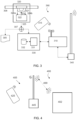
- FIG. 5 showing a schematic representation of a system according to another embodiment described herein;
- FIG. 6 illustrating a system according to an embodiment described herein
- FIG. 7 showing a schematic representation of a part of the disclosed system on the supplying vessel according to an embodiment in which access to a wide area network is provided via a gateway device.
- FIG. 8 is a flow chart of a process for monitoring and verifying bunker fuel exchange between marine vessels, according to an example of the present disclosure.
- a system for streamlining the bunker delivery process in the maritime industry.
- the system provides a bunker delivery platform to improve efficiency and to build transparency into the bunker delivery process.
- the platform allows for stakeholders in the bunker delivery process, such as the Barge Master of the bunker barge, or supplying marine vessel, and the Chief Engineer of the receiving marine vessel, to monitor and verify, among other things, the quantity and/or quality of the fuel in real time during the delivery process.
- a dashboard with data indicating key characteristics of the process is made available to each of the stakeholders so that they can verify the process with respect to a preestablished contract stating certain criteria which have to be met.
- the system may comprise other types of data capture devices than simply the measurement apparatus. Any other type of data useful in substantiating or otherwise authenticating the contractual or regulatory requirements may be used.
- the system may comprise a memory or have access to a database in which data relative to the delivery session may be stored, like a name of the vessel, the type of fuel being delivered, etc.
- the data capture device may be a GPS device or an AIS system, used for automatically tracking vessel positions, for providing global coordinates of the position of the vessel or it may be a timer for providing date and/or time information of the delivery session.
- Embodiments of the system described herein include a private local area wireless network, built around a wireless router which is preferably on the supplying marine vessel.
- the monitoring unit and the router are interconnected via a physical local area network connection and the router is also connected to a wireless access point which is configured to implement a point-to-point bi-directional wireless communication link to a corresponding client wireless router on the receiving marine vessel, preferably in direct line of site with the wireless access point on the supplying marine vessel.
- Authorized users having mobile communications devices on the receiving vessel can therefore access the monitoring unit via this private local area wireless network using a web browser for example.
- the system may also produce an electronic Bunker Delivery Note as well as other documents required for auditing the delivery process.
- the Bunker Delivery Note may be made available to the Chief Engineer via the private local area network.
- both parties When both parties agree that the electronic documents correspond to the quantity and quality of the delivered fuel, they can each provide their electronic signatures via the portal, indicating that the delivery process has been verified. Details of the contract may be stored in the system so that the parties can perform the verification. These details may include a bunker delivery sampling procedures form, handling procedures form, ullages report for initial pre-delivery measurements, bunker analysis report, safety checklists, the amount of fuel expected, and so on. After delivery, further electronic documents may be produced, such as a bunker delivery receipt, an ullage report and a statement of facts.
- the system provides the advantage that electronic documents can be automatically generated, based on real-time in-line measurements received from different sensors in the measurement apparatus while the fuel is being delivered. Errors which may occur due to manual data entry are thus avoided.
- the documents can be exchanged back and forth between the supplying vessel and the receiving vessel over the private wireless network for cross verification. Electronic documents can also readily be signed to indicate a party's approval.
- access to a wide area network may also be provided by connecting a gateway device to the router having access to a satellite connection for example.
- an electronic invoice for the delivery may be sent directly to the customer based on the electronic bunker delivery note.
- the monitoring unit is further configured to upload the measurements to the cloud via the gateway device so that they may be consulted by other authorized parties in other locations.
- the system thus provides automatic, real-time reporting to other stakeholders in the bunkering process apart from the barge master of the delivery vessel and the Chief Engineer of the receiving vessel, such as port authorities, customs authorities, and so on.
- a bunkering session is illustrated 100 , in which bunker fuel is transferred from a storage tank 103 of a supplying marine vessel, a bunker barge 102 , through a bunker line 108 to one or more fuel tanks 106 of a receiving vessel 105 .
- Bunker barges are usually smaller, and shorter in height, than the receiving vessel and so the bunker barge may have a crane to lift the bunker line high enough to allow the bunker line to be connected to the receiving vessel's bunkering manifold.
- FIG. 2 shows a schematic representation of a Coriolis mass flowmeter 221 , which may be inserted into the bunker line 208 , and which may be used to measure the flow rate of fluid, the bunker fuel, as it passes through the bunker line.
- a magnet and coil assembly located at a certain part of the mass flowmeter, is driven by an electrical signal 223 , which causes a part of the mass flowmeter to vibrate, or oscillate, during operation. The way the different parts of the flowmeter oscillate depends on the mass flow rate of the fluid travelling through the mass flowmeter. At least two further magnet and coil assemblies are placed on the mass flowmeter at different locations along the flow of the fluid to operate as sensors.
- the vibrations of these parts of the flowmeter cause the sensors to provide electrical signals which are out of phase with one another.
- the sensors produce sinusoidal signals 224 a , 224 b representing the motion of the corresponding part of the mass flowmeter, caused by the flow of the fluid through the mass flowmeter.
- the mass flowmeter usually operates along with a transmitter/controller 222 to drive the mass flowmeter and to receive the sensor signals and process them.
- the transmitter/controller usually called simply a transmitter, may output such parameters 225 as mass and volume flow, net product content or flow, temperature, density or concentration, for example.
- Coriolis mass flowmeters use the Coriolis principle to measure the mass flow rate (kilograms per hour) and density directly. Such mass flowmeters can be configured to display mass flow rate, volumetric flow rate, or a combination of both. Some mass flowmeters may also present the temperature of the liquid or liquid mixture being measured. The flow rate can be calculated from the phase difference between the signals received from the different sensors. Density can be calculated from the frequency of the signal from the sensors.
- FIG. 3 shows a schematic representation of a part of a system 390 for monitoring and verifying a delivery process during which a fluid is delivered, via a bunker line 308 , from a supplying marine vessel to a receiving marine vessel, as described herein.
- FIG. 3 shows a part of the bunker line 308 through which the fluid is delivered.
- the system comprises a data capture device, which in this case is a measurement apparatus 320 , engaged in some way with the bunker line to allow for certain parameters related to the delivery process to be measured.
- the measurement apparatus may comprise a mass flowmeter 321 .
- the mass flowmeter may be a Coriolis mass flowmeter inserted into the bunker line so that the mass flowmeter can measure the mass flow rate of the fluid as it travels through the bunker line.
- the measurement apparatus may have different types of sensors to allow it to measure different parameters. For example, a temperature sensor may engage with the bunker line by probing into the flow of the fluid in the bunker line.
- sensors are possible, for example, a timer, one or more pressure sensors to measure the pressure of the fluid in the bunker line or to measure a pressure difference along a part of the bunker line, a rheometer to measure viscosity of the fluid or one or more from a number of different chemical sensors to detect such things as a percentage water content in the fluid; a percentage sediment content in the fluid; a percentage Sulphur content in the fluid; or a percentage ash content in the fluid, and so on.
- a timer one or more pressure sensors to measure the pressure of the fluid in the bunker line or to measure a pressure difference along a part of the bunker line
- a rheometer to measure viscosity of the fluid or one or more from a number of different chemical sensors to detect such things as a percentage water content in the fluid; a percentage sediment content in the fluid; a percentage Sulphur content in the fluid; or a percentage ash content in the fluid, and so on.
- the mass flowmeter is shown in combination with its transmitter 322 , which provides the electrical signals 323 to cause the oscillations in the mass flowmeter and which receives the electrical signals 324 a , 324 b from the sensors in the mass flowmeter, allowing the mass flow rate of the fluid through the bunker line to be calculated and for the density of the fluid to be calculated.
- the mass flowmeter is located at the supplying marine vessel.
- the system further comprises a monitoring unit 330 , which is connected to the measurement apparatus so that the monitoring unit can receive the measured parameters 325 as they are measured.
- the monitoring unit comprises 330 at least one memory 332 for storing the measured parameters and at least one processor 331 to process the measured parameters.
- the parameters may be measured at different time intervals during the delivery process and fed to the monitoring unit.
- the processor may be configured to generate an electronic record comprising at least one parameter from the received set of measured parameters.
- the electronic record may otherwise, or in addition, comprise a datum derived or otherwise calculated from one or more of the measured parameters.
- the measurement apparatus further comprises a flow computer (not shown in FIG.
- Mass flowmeter manufacturers sometimes provide the mass flowmeter and flow computer together as a unit in order to improve metrology performance and to reduce measurement uncertainty thus ensuring compliance with measurement contracts.
- Such units are usually certified by a Weights and Measures authority or by a port authority or other similar metrology authority responsible for ensuring that the units comply with industry-accepted metrology requirements.
- the monitoring unit collects the measurement parameters from the mass flowmeter in read-only mode, thus ensuring that the data received by the monitoring unit meets the compliances certified by the relevant authority.
- the monitoring unit reads the measurement parameters directly from the mass flowmeter and it is the combination of mass flowmeter and monitoring unit which is certified by the relevant authority.
- the processor of the monitoring unit is further configured to generate a network-accessible dashboard, accessible, preferably using a web browser, to the first and second users having access to the private local area network, the dashboard being configured to present the electronic record to the first and second users and to accept an electronic signature of each of the first and second users to indicate, respectively, whether the first and second users have each positively verified the electronic record with respect to said preestablished contractual terms, the delivery process being verified when both the first and second users have provided their electronic signatures.
- a network-accessible dashboard accessible, preferably using a web browser
- a printer 305 may be used on the supplying vessel to print a bunker delivery receipt. This is shown in FIG. 3 , where after the bunkering process has been completed, a switch 307 can be actioned to switch the measurement apparatus output to go to the printer. Embodiments also exist without the printer and the switch.
- the monitoring unit is connected, via a physical communications network cable, to a wireless router 310 on the supplying marine vessel, or barge. Users on the barge can thus connect to the monitoring unit using a web browser to view the measurement results using a mobile communications device such as a telephone or a tablet computer 315 for example.
- the monitoring unit is configured to run a software application to present the measurement data, or other data derived or otherwise calculated from the measurement data, in a dashboard accessible by web browser.
- the data capture device is a video capture device
- the monitoring unit is configured to present all or part of video content captured during at least a part of a process during the delivery session in the dashboard accessible via a web browser.
- the data capture device captures data from a memory or from a database
- the monitoring unit is configured to present the captured data in the dashboard.
- the system further comprises an antenna, connected by a physical communications network cable to the wireless router and configured as a wireless access point 340 to provide a point-to-point wireless communications link to a corresponding further transceiver on the receiving vessel, the further transceiver being configured as a client device to the access point.
- the placement of the access point and the client on their respective vessels is chosen to provide for line-of-sight communication between the barge and the receiving vessel via the point-to-point communications link.
- FIG. 3 shows the system up to the wireless access point.
- the client device and the receiving vessel are not shown.
- the further transceiver may also have an antenna and may provide wireless connection to one or more computers or mobile devices on the vessel.
- the further transceiver may be part of a mobile communications device such as a smartphone or a tablet computer or other mobile communications device.
- the point-to-point communications network is preferably a private network.
- the network thus created including wireless devices on the receiving vessel and wireless devices on the barge and the monitoring unit, can be said to be an Intranet.
- FIG. 4 shows the barge and its system components 402 , graphically represented by a box, in point-to-point wireless communication 499 with the receiving vessel 405 .
- the receiving vessel has the antenna 445 configured as a router which is a client of the access point on the barge.
- Authorized users on the receiving vessel can then connect to the network using their mobile communications devices 425 .
- the receiving vessel 505 further comprises a further router 546 , connected to the further antenna 545 , allowing users 525 on the receiving vessel to connect to the network 599 .
- the point-to-point communications link is completed using a transceiver of a mobile communications device used on the vessel.
- FIG. 6 illustrates an example of a system 600 in which an embodiment of the invention may be deployed.
- the data capture device is a measurement apparatus 620 , which measures a set of parameters related to the delivery process by engaging with the bunker line 608 through which the fuel delivery takes place.
- the measurement data is read off and stored by the monitoring unit 630 .
- the monitoring unit is also configured to run an application to produce a network-accessible dashboard in which the measurements are presented.
- the dashboard may be accessible using a web browser, over the private wireless communications network.
- the monitoring unit is configured to treat the captured video data of all or part of a process used during the delivery session to allow it to be displayed in the dashboard.
- process 800 can include capturing at least one datum related to a delivery process of a fluid from a supplying marine vessel to a receiving marine vessel or measuring at least one set of parameters relative to one or more from: a mass flow rate of the fluid through at least a part of the bunker line, a physical property of the fluid, a chemical property of the fluid, and a quality of the fluid.
Landscapes
- Physics & Mathematics (AREA)
- General Physics & Mathematics (AREA)
- Engineering & Computer Science (AREA)
- Fluid Mechanics (AREA)
- Chemical & Material Sciences (AREA)
- Ocean & Marine Engineering (AREA)
- Mechanical Engineering (AREA)
- Combustion & Propulsion (AREA)
- Computer Networks & Wireless Communication (AREA)
- Health & Medical Sciences (AREA)
- Life Sciences & Earth Sciences (AREA)
- Analytical Chemistry (AREA)
- Biochemistry (AREA)
- General Health & Medical Sciences (AREA)
- Immunology (AREA)
- Pathology (AREA)
- Environmental & Geological Engineering (AREA)
- Arrangements For Transmission Of Measured Signals (AREA)
Abstract
Description
characterized in that:
the system further comprises a private local area network comprising:
a first wireless transceiver configured to be operably connected to the monitoring unit, the first wireless transceiver being configured to provide wireless access to the monitoring unit by one or more wireless communications devices of one or more authorized first users on the supplying marine vessel;
a second wireless transceiver configured to be operably connected to the first wireless transceiver and configured to provide a point-to-point wireless link between the supplying marine vessel and the receiving marine vessel; and
a third wireless transceiver, for location on the receiving marine vessel, configured to provide wireless access to the second wireless transceiver by one or more wireless communication devices of one or more authorized second users on the receiving marine vessel via the point-to-point wireless link;
the processor being further configured to generate a dashboard, accessible to the first and second users having access to the private local area network, the dashboard being configured to present the electronic record to the first and second users and to accept an electronic signature of each of the first and second users to indicate, respectively, whether the first and second users have each positively verified the electronic record with respect to said preestablished contractual terms, the delivery process being verified when both the first and second users have provided their electronic signatures.
generating, using a processor, an electronic record comprising at least one parameter from the set of parameters;
storing the electronic record in a memory;
generating, using the processor, a dashboard, the dashboard being configured to present the electronic record and to accept an electronic signature from at least two users, to indicate whether the two users have each positively verified the electronic record with respect to said preestablished contractual terms;
providing access to the dashboard, on a private local area network, by a wireless communications device of at least one authorized first user on the supplying marine vessel, via a wireless router on the supplying marine vessel;
providing access to the dashboard, on the private local area network, by a wireless communications device of at least one authorized second user on the receiving marine vessel, via a point-to-point wireless communications channel between a wireless access point on the supplying marine vessel and a wireless client device of the wireless access point, the wireless client device being on the receiving marine vessel; and
receiving, via the dashboard, an electronic signature of the authorized first user to indicate whether the authorized first user has verified the electronic record with respect to the preestablished contractual terms and an electronic signature of the authorized second user to indicate whether the second user has verified the electronic record with respect to the preestablished contractual terms, the delivery process being verified when both of said electronic signatures have been received.
Claims (20)
Priority Applications (1)
| Application Number | Priority Date | Filing Date | Title |
|---|---|---|---|
| US17/879,684 US12241768B2 (en) | 2021-08-02 | 2022-08-02 | System and a process for monitoring and verifying bunker fuel exchange between marine vessels |
Applications Claiming Priority (7)
| Application Number | Priority Date | Filing Date | Title |
|---|---|---|---|
| SG10202108445U | 2021-08-02 | ||
| EP21189240.1A EP4130689B1 (en) | 2021-08-02 | 2021-08-02 | A system and a process for monitoring and verifying bunker fuel exchange between marine vessels |
| EP21189240.1 | 2021-08-02 | ||
| SG10202108445U | 2021-08-02 | ||
| EP21189240 | 2021-08-02 | ||
| US17/879,684 US12241768B2 (en) | 2021-08-02 | 2022-08-02 | System and a process for monitoring and verifying bunker fuel exchange between marine vessels |
| US17/879,606 US12242997B2 (en) | 2021-08-02 | 2022-08-02 | System and a process for monitoring and verifying bunker fuel exchange between marine vessels |
Related Parent Applications (1)
| Application Number | Title | Priority Date | Filing Date |
|---|---|---|---|
| US17/879,606 Continuation-In-Part US12242997B2 (en) | 2021-08-02 | 2022-08-02 | System and a process for monitoring and verifying bunker fuel exchange between marine vessels |
Publications (2)
| Publication Number | Publication Date |
|---|---|
| US20230036245A1 US20230036245A1 (en) | 2023-02-02 |
| US12241768B2 true US12241768B2 (en) | 2025-03-04 |
Family
ID=85037692
Family Applications (1)
| Application Number | Title | Priority Date | Filing Date |
|---|---|---|---|
| US17/879,684 Active US12241768B2 (en) | 2021-08-02 | 2022-08-02 | System and a process for monitoring and verifying bunker fuel exchange between marine vessels |
Country Status (1)
| Country | Link |
|---|---|
| US (1) | US12241768B2 (en) |
Citations (4)
| Publication number | Priority date | Publication date | Assignee | Title |
|---|---|---|---|---|
| US20100217536A1 (en) * | 2009-02-26 | 2010-08-26 | Invensys Systems, Inc. | Bunker fuel transfer |
| US20120109543A1 (en) | 2009-07-13 | 2012-05-03 | Micro Motion, Inc. | Meter electronics and fluid quantification method for a fluid being transferred |
| WO2015165468A1 (en) | 2014-04-28 | 2015-11-05 | A.P. Møller - Mærsk A/S | A system and method for measuring the amount of fuel delivered in a bunkering operation |
| CN112132383A (en) | 2020-08-07 | 2020-12-25 | 张军 | LNG tank fuel supply transaction method, transaction system and storage medium |
-
2022
- 2022-08-02 US US17/879,684 patent/US12241768B2/en active Active
Patent Citations (4)
| Publication number | Priority date | Publication date | Assignee | Title |
|---|---|---|---|---|
| US20100217536A1 (en) * | 2009-02-26 | 2010-08-26 | Invensys Systems, Inc. | Bunker fuel transfer |
| US20120109543A1 (en) | 2009-07-13 | 2012-05-03 | Micro Motion, Inc. | Meter electronics and fluid quantification method for a fluid being transferred |
| WO2015165468A1 (en) | 2014-04-28 | 2015-11-05 | A.P. Møller - Mærsk A/S | A system and method for measuring the amount of fuel delivered in a bunkering operation |
| CN112132383A (en) | 2020-08-07 | 2020-12-25 | 张军 | LNG tank fuel supply transaction method, transaction system and storage medium |
Non-Patent Citations (2)
| Title |
|---|
| "Hazardous consequence dynamic simulation of LNG spill on water for ship-to-ship bunkering" Published by Elsevier (Year: 2017). * |
| U.S. Appl. No. 17/879,606, "Non-Final Office Action", mailed Oct. 6, 2023, 13 pages. |
Also Published As
| Publication number | Publication date |
|---|---|
| US20230036245A1 (en) | 2023-02-02 |
Similar Documents
| Publication | Publication Date | Title |
|---|---|---|
| JP5509327B2 (en) | Meter electronics and fluid quantification method for fluid in transit | |
| US20100217536A1 (en) | Bunker fuel transfer | |
| US20220334038A1 (en) | Measuring device for determining the density, the mass flow and/or the viscosity of a gas-charged liquid, processing system having such a measuring device, and method for monitoring a gas-charged liquid | |
| US12241768B2 (en) | System and a process for monitoring and verifying bunker fuel exchange between marine vessels | |
| US12242997B2 (en) | System and a process for monitoring and verifying bunker fuel exchange between marine vessels | |
| EP4130689B1 (en) | A system and a process for monitoring and verifying bunker fuel exchange between marine vessels | |
| KR101938844B1 (en) | Differential flowmeter tool | |
| CA2498839C (en) | Propane measurement using a coriolis flowmeter | |
| CN117795297A (en) | Systems and methods for monitoring and verifying the exchange of marine fuel oil between marine vessels | |
| AU2015391008B2 (en) | Detecting an inaccurate flow rate measurement by a vibratory meter | |
| HK40101584A (en) | System and method for monitoring and verifying bunker fuel exchange between marine vessels | |
| METERING | Maersk leads the way | |
| HK1171078B (en) | Meter electronics and fluid quantification method for a fluid being transferred |
Legal Events
| Date | Code | Title | Description |
|---|---|---|---|
| FEPP | Fee payment procedure |
Free format text: ENTITY STATUS SET TO UNDISCOUNTED (ORIGINAL EVENT CODE: BIG.); ENTITY STATUS OF PATENT OWNER: LARGE ENTITY |
|
| AS | Assignment |
Owner name: ADP CLEAR PTE LTD., SINGAPORE Free format text: ASSIGNMENT OF ASSIGNORS INTEREST;ASSIGNORS:CROSS, ALISTAIR;BARON, TYLER;REEL/FRAME:060708/0991 Effective date: 20220802 |
|
| STPP | Information on status: patent application and granting procedure in general |
Free format text: DOCKETED NEW CASE - READY FOR EXAMINATION |
|
| STPP | Information on status: patent application and granting procedure in general |
Free format text: NON FINAL ACTION MAILED |
|
| STPP | Information on status: patent application and granting procedure in general |
Free format text: RESPONSE TO NON-FINAL OFFICE ACTION ENTERED AND FORWARDED TO EXAMINER |
|
| STPP | Information on status: patent application and granting procedure in general |
Free format text: NOTICE OF ALLOWANCE MAILED -- APPLICATION RECEIVED IN OFFICE OF PUBLICATIONS |
|
| STPP | Information on status: patent application and granting procedure in general |
Free format text: AWAITING TC RESP., ISSUE FEE NOT PAID |
|
| STPP | Information on status: patent application and granting procedure in general |
Free format text: PUBLICATIONS -- ISSUE FEE PAYMENT VERIFIED |
|
| STCF | Information on status: patent grant |
Free format text: PATENTED CASE |