US1223402A - Cement-applying machine. - Google Patents
Cement-applying machine. Download PDFInfo
- Publication number
- US1223402A US1223402A US3980215A US3980215A US1223402A US 1223402 A US1223402 A US 1223402A US 3980215 A US3980215 A US 3980215A US 3980215 A US3980215 A US 3980215A US 1223402 A US1223402 A US 1223402A
- Authority
- US
- United States
- Prior art keywords
- cement
- brush
- margin
- applying
- rotary
- Prior art date
- Legal status (The legal status is an assumption and is not a legal conclusion. Google has not performed a legal analysis and makes no representation as to the accuracy of the status listed.)
- Expired - Lifetime
Links
- 239000004568 cement Substances 0.000 description 90
- 239000000463 material Substances 0.000 description 69
- 230000002093 peripheral effect Effects 0.000 description 5
- 239000010985 leather Substances 0.000 description 4
- 230000000306 recurrent effect Effects 0.000 description 3
- 230000001276 controlling effect Effects 0.000 description 2
- 239000004744 fabric Substances 0.000 description 2
- 239000004615 ingredient Substances 0.000 description 2
- 238000004519 manufacturing process Methods 0.000 description 2
- 230000001105 regulatory effect Effects 0.000 description 2
- BWWVAEOLVKTZFQ-NTZNESFSSA-N Amdinocillin Chemical compound N([C@H]1[C@H]2SC([C@@H](N2C1=O)C(O)=O)(C)C)=CN1CCCCCC1 BWWVAEOLVKTZFQ-NTZNESFSSA-N 0.000 description 1
- RYGMFSIKBFXOCR-UHFFFAOYSA-N Copper Chemical compound [Cu] RYGMFSIKBFXOCR-UHFFFAOYSA-N 0.000 description 1
- 241000235319 Havinthus Species 0.000 description 1
- 241001076195 Lampsilis ovata Species 0.000 description 1
- BQCADISMDOOEFD-UHFFFAOYSA-N Silver Chemical compound [Ag] BQCADISMDOOEFD-UHFFFAOYSA-N 0.000 description 1
- 230000015572 biosynthetic process Effects 0.000 description 1
- 238000010276 construction Methods 0.000 description 1
- 230000003247 decreasing effect Effects 0.000 description 1
- 230000000994 depressogenic effect Effects 0.000 description 1
- 230000002708 enhancing effect Effects 0.000 description 1
- 239000012634 fragment Substances 0.000 description 1
- 210000003127 knee Anatomy 0.000 description 1
- 238000000034 method Methods 0.000 description 1
- 230000000630 rising effect Effects 0.000 description 1
- 238000000926 separation method Methods 0.000 description 1
- 229910052709 silver Inorganic materials 0.000 description 1
- 239000000126 substance Substances 0.000 description 1
Images


Classifications
-
- A—HUMAN NECESSITIES
- A43—FOOTWEAR
- A43D—MACHINES, TOOLS, EQUIPMENT OR METHODS FOR MANUFACTURING OR REPAIRING FOOTWEAR
- A43D95/00—Shoe-finishing machines
- A43D95/06—Machines for colouring or chemical treatment; Ornamenting the sole bottoms
Definitions
- My invention relatesvto cement applying machines applicable for providing the margins of flexible material, such as leather, cloth, and fabrics of various kinds, with a narrow band of cement inthe manufacture of shoes, gloves, pocket-books and containers of various kinds. At times these margins are skived, especially when the flexible material operated on is in the nature of shoe uppers.
- the margins in the course of manufacture of the articles are usually folded, and when it is the intention to fold-the margin, the band of cement is usually approximately twice the width. of the fold, so that both the surfaces within the fold shall be cemented prior to folding, for the reason that the cement employed in this art for the purpose specified has volatile ingredients and adheres best to the surface of the material at its moment of application thereto, the outer Surface of the cement retaining its tackiness for a period of time after its application to the material.
- the cement usually used in general work of this character has a rubber foundation and is known in the trade as rubber cement, and the cement used.
- certain characters of material kfor instance, oiled leather or glazed material, contains an oil-absorbing ingredient, Such .as chalk or other earthy substance, forming a thicker cement, known in the trade as white 'or pink cement, which for convenience will hereinafter be termed thick cement.
- thick cement Such cements are highly inflammable.
- It is the object of my'invention further to provide means whereby a pocket of cement is formed at the side of the rotary cementapplying part for providing a body of cement .which is drawn upon for insuring application of a suiciently thick film of cement upon the margin of the material; further to provide means whereby Stringing of the cement at the side of the rotary cementapplying part is controlled; further to provide novel means for supporting and guiding the margin of the material in the cement-applying operation; and, further to provide novel arrangement of means for cementing the margins of closed Vamps.y
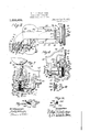
- Figure 1 is a front elevation of my improved device, partly broken away, employed in cementing the margin of a closed vamp.
- Fig. 2 is a vertical section of the cementapplying head of my improved device, taken on the line 2-2 of Fig. 3.
- Fig. 3 is an end elevation of my improved device.
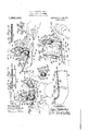
- Fig. 4 is a cross-section of the cement-applying head taken on the line 4-4 of Fig. 7.
- Fig. 5 is a cross-section of the same taken on the line 5 5 of Fig. 7.
- Fig. 6 is a cross-section of the same taken on the line 6 6 of Fig. 7.
- Fig. 7 is a front elevation of the cementapplying head.
- Fig. 8 is a rear elevation of the same.
- Fig. 9 is a plan View of my improved device, the cement-pot being broken away on the section line 9-9 of Fig. 3.
- Fig. 10 is a sectional detail taken on the line 10-10 of Fig. 3, showing the adjusting means for the material-support.
- Fig. 1l is a longitudinal sectional detail taken on the line 11--11 of Fig. 8, showing the adjusting means for the gage.
- Fig. 12 is a cross-sectional detail of the same taken on the line 12-12 of Fig. 11.
- Fig. 13 is a perspective view of the cement-applying head employed in cementing a concavely curved margin, viewed from the feeding-in side.
- Fig. 14 is a perspective view of the same employed in cementing a straight margin, viewed from the feeding-out side.
- Fig. 15 is a perspective view of the same, viewed from the rear and feeding-in side.
- Fig. 16 is a plan view of a closed vamp laid flat, the margin of which is provided with a narrow band of cement in my improved device.
- Fig. 17 is an enlarged plan view of a piece of material having its margin cemented in my improved device, and partly folded, and partly broken away, and illustrating the crossing relation of the cement ridges within the ⁇ fold.
- Fig. 18 is a vertical section of the same
- Fig. 19 is a cross-section of thel same, taken on the line 19-19 of Fig. 17.
- Fig. 2O is a fragment showing further the location of the cement wiping linger.
- the frame of the machine in its preferred form comprises a column 21 extending upwardly from a base 22, which is arranged to be secured to a suitable support or table, indicated at 23, as by means of screws passing through holes 24 in the base.
- the cementapplying instrumentalities are mounted on an arm which extends laterally and forwardly from the column in such manner that the cement-applying instrumentalities are mounted free of the frame and distanced sufiiciently from the column and above the support or table, as to permit the margins of flexible material, indicated at m, of various sizes and shapes, for instance, long straight pieces, (see Figs. 14 and 15), curved pieces, (see Fig. 13), closed pieces, such as closed Vamps, (see Fig. 1), and the like, to be fed past the cement-applying instrumentalities while stretched 0r held between the hands of the operator, without interference or contact by said pieces or the hands of the operator with the frame of the machine or itsV table or support.
- the machine parts are out of line with the material supporting surface ofthe materialsupport and the adjacent cement-applying portion of the rotary cement-aplvlying brush.
- the arm is exemplified as comprising a laterally extending portion 25 and forwardly extending portions 26, 27.
- the portion 26 comprises a bearing 28 for receiving the throat-portion 29 of a suitable cement-pot 30, held in place by clamping the pot in the bearing by means of a cement-conveying head 3l having threaded connection 32 with the lower end of the throat-portion.
- a cement passage 33 extends through the head and has therein a valve 31 by means of which the fiow of cement may be regulated or entirely shut off, as desired.
- a cementsupplying roll 35 is fast on a shaft 36 journaled in bearings 37 in the head and has a I gear 38 fast thereon, ⁇ It is provided with cement-supplying pockets 39 for conveying the cement. bearings 37 to points in substantial line with that portion of the periphery of the roll 35 acted on by the rotary cement-applying brush for preventing the wiping of cement upon thefend-face of the'roll.
- the cement is arranged to be applied in the present exemplification of my device by aY rotary cement-applying part, exemplified as a rotary brush 43, preferably com rising annularrows of bristles 44 in a bushing 45, the rows of bristles being separated by flat rings 46 about the bushing, ay flange 47 being at one end of the brush.
- the brush is fixed by means of a set-screw 4-8 to a sleeve 49, which is received about a shaft 50, and held to the shaft so as to rotate therewith by means of being provided with an end slot 51 received about a pin 52 inthe shaft.
- the bushing of the brush overhangs the sleeve at its outer end for providing an annular end space 55 between the shaft 50 and said sleeve.
- a cement-control 58 is located at the feedout side of the brush.
- This cement-control is exemplified in the form of a plate having an annular flange 59 about its axis, this annular Harige being received as a. bearing about the end of the shaft 50 in the annular end space 55.
- a screw 60 holds the brush and plate on the shaft, the screw being threaded into the end of the shaft, as shown at 61, and having a thread reverse in direction to the direction of rotation-of the shaft, so as to hold the screw on the shaft and prevent its accidental turning with relation to the shaft during operation of the machine.
- Rotation is imparted to the rotary cementapplying brush byvmeans of a drive-shaft 64 journaled in a bearing 65 in the upper end of the column and a bearing 66 in the outer end of the arm, and provided with suitable driving means preferably of such character as to cause rotation and permit cessation of rotation of the rotary cement-applying brush, under manual control of the operator during operation of the machine.
- suitable driving means preferably of such character as to cause rotation and permit cessation of rotation of the rotary cement-applying brush, under manual control of the operator during operation of the machine.
- manual control includes any control by the operator during the operation of the machine, whether by hand, foot, knee, or other physical manner.
- these driving means as comprising a pulley 67 arranged for receiving a belt 68 thereabout for rotating the same.
- the pulley ⁇ is normally loose on the shaft.
- a clutch represented as a friction clutch, between the pulley and the drive-shaft, and arranged when in clutched relation to impart motion from the pulley to the drive-shaft, the drive-shaft being nonrotating during ⁇ unclutched relation of the clutch.
- the clutch may be of suitable construction
- Side-cheeks 40 extend from the i and is exemplified as comprising a member 71 fast on the drive-shaft and a member 72 fast with the pulley 67, a friction-band 73 being between said members.
- a lever 75 is pivoted on a bolt 76 on the column andcomprises an actuatorarm 77, a brake-arm 78, and an operating arm 79.
- the actuator-arm contacts a button 80 of the clutch-member 72 for pushing the clutch-members into clutching relation.
- the brake-arm has a brake-shoe 81 thereon coactin with an annular brake-surface 82 on the c utch-member 71..
- the operating arm connects by a connection 83 with a treadle 84 suitably placed on the lHoor.
- the lever 75 is normally retracted by a spring S5, connected at one end with thecolumn and at its other end with the operating arm.
- The'drive-shaft is provided with a gear 86 fast thereon, which meshes with an intermediate gear 87 fast on al shaft 88 journaled in a bearing Si) in the forwardly extending portion 27 of the arm of the frame.
- the gear 87 meshes with a gear 91 on the brush-shaft 5() jonrnaled in a bearing 92 in said forwardly extending portion 27 of the arm.
- the shaft 88 is also provided with a gear 93 fast thereon, which meshes with the gear 38 fast on the shaft 36, to which the cement-supplying roller 35 is secured, for rotating the latter preferably in the direction of the arrow a, the rotary cement-applying brush being preferably rotated in the direction of the arrow I).
- a cement-wiping finger 95 is on an arm 96 secured to the head 31, as by means of screws 97, and is provided with a throat 98.
- TheI cement-wipingI linger is arranged to contact the side of the flange 47 so as to wipe the cement which may be received on said fiange through said throat on to the bristles of the brush for keeping said flange clean.
- the rotary cement-applying ⁇ brush is arranged to apply a narrow band of cement, indicated at 100, upon the margin of the iexible material.
- the margin of the iexible material is arranged, during the cementapplication, to be supported on a forwardly extending support 101, located at the side, namely the normal-feeding-in side, of the rotary cement-applying brush.
- This support of a clamp-screw 103 received through a slot' 101 in the support and threaded into the gage.
- the meeting faces of the support and gage are curved along the line of adjusting movement of the gage for maintaining the ymaterial-contacted face of the gage in ⁇ proper relation to the brush.
- the support- 1s also arranged to be raised and lowered and held in adjusted positions, as by means of clamp-screws 107 received through a slot 108 in the shank 109 of the support and threaded in threaded apertures 110 of the arm.
- the support is provided with a laterally extending and downwardly drooping wing 114; and the gage is provided with an upwardly curving wing 115 forming a wide mouth 116 for the recess 117 of the gage in Which the margin of the material is received, the said recess preferably contracting toward the upright wall 118 of the gage, against which the edge 119 ofthe margin 120 of the material is arranged to be received when feeding the material past the gage and the rotary cement-applying part.
- the clearance in the recess 117 is preferably sufficiently high to permit the passage of seams therethrough.
- the material-supporting face of the material-support or horn preferably extends into the longitudinal projection of the periphery of the lrotary cement-applying brush, (see Figs. 1, 2, 3, 4 and 6), the said supporting face being preferably a curved face preferably slightly approaching the axis of rotation of the brush at its reai portion, so as to accommodate different thicknesses of leather having different widths of margin to be cemented, and insuring that when the margin is skived, as at 121, the thin edge thereof has support.
- Thicker leathers are usually skived with a wider margin and provided with a wider band of cement than thinner leathers. If, therefore the support and gage are adjusted for a thicker leather and wider margin of cement-application, the support or horn is lowered and the gage shifted rearwardly.
- the material-supporting face of the support or horn approaching the axis of the rotatable brush at its rear insures, that when so adjusted, intimate contact between the outer edge of the margin being cemented and the rotary brush is assured.
- the normal direction of feeding the material is indicated by the arrow c, in Figs. 1, 13, 14 and 15, the side d of the rotary cement-applying part being therefore the normal feeding-1n side and the side e of said part being the normal feeding-out side thereof.
- the gage with its support is located at the feeding-in side of the rotary cement-applying brush and its edge proximate thereto is preferably spaced from the bristles of the brush by a slight space 122 for permitting the material to be iiexed about the periphery of the brush without undue flexure of the bristles of the brush and for insuring intimate contact between the margin being cemented and the periphery of the brush. This space also permits the ready passage of cross-seams 123 when such are contained in the margin.
- the feeding of the material is preferably accomplished by hand, the material being held by one hand of the operator at the feeding-in side of the rotary cementapplying part, as indicated at 124, and by the other hand of the operator at the feeding-out side of said rotary cement-applying part, as indicated at 125, the margin being supported on the horn and guided by the gage and passed with a quick movement across said gage and the rotary cementapplying part.
- the cement is laid in alternate thicker and thinner lines forming ridges 126 arranged obliquely across the margin being cemented in a direction which is the resultant of the feeding movement and the rotary movement of the cement-applying brush, as indicated in Figs. 13, 14, 16, 17 and 18.
- the fold of the margin is usually formed with a crease 127 extending lengthwise of the middle of the band of cement. ⁇ When the fold 128 of the margin is laid upon the body portion 129 ofthe margin, the lines or ridges of cement at the respective sides of the crease extend in opposite directions and cross relations, so that the uniformly recurrent thick portions of the cement applied will lap each other and cause adhesion between the folded and body portions of the margin when pressed together, as seen more particularly in Fig. 18.
- the degree of pressure of the margin of the material upon the periphery of the brush is readily regulated by the force applied by the hands in stretching the material between the hands at the point of cementapplication and also by the direction above or below the plane of the cement-applying portion of the brush in which the feedingout portion of the margin of the material is held.
- the lateral feeding movement of the material and pressure upon the bristles also causes lateral flexure of the bristles of the l ing roller by the brush.
- This cement-control device preferably comprises an inner annular portion 131 which makes intimate contact with the end of the hub of the brush for preventing the seeping'of cement to the brush shaft.
- the cement-control device is provided with a laterally sloping wall 132 at the side of the initial pa rt of the cement-feeding portion of the brush, adjacent to the cementsupplying roll, forming a clearancespace 133 for the cement at the feeding-out side of said brush which tapers toward the brush, this clearance-space permitting ready wiping of the cement off the cement-supply-
- This laterally sloping wall merges with a radially extending wall 134 which extends radially to substantially the peripheral line of the brush in close proximity to the bristles of the brush, and in connection with said first-named wall directs the cement at the feeding-out side of the brush toward the ends of the bristles thereof.
- the peripheral edge of the plate at that portion thereof proximate to the cement-applying portion of the brush, exempliiied as its lower edge, is located inwardly from the longitudinal projection of the periphery of the rotary cement-applying brush, as shown at 136, so that the bristles of the brush project beyond said edge ⁇ and said edge is preferably bent away from said brush, at the cement-applying portion of the latter, as shown at 137, for forming a pocket 138 in which excess cement from the bristles may be received and for permitting substantial flexure ofthe bristles at the feeding-out side of the brush.
- this pocket has a gradually widening mouth which then gradually contracts toward the cement-returning portion of the periphery of the brush, and merges into awall 139 adjacent to thc cement-supplying roller, this latter wall approaching the i side kof the rotary brush and preferably extending beyond the line of the periphery of the brush, for directing any cement there may be in said pocket toward the periphery of the brush, the rotation of the brush in its direction b having a tendency to draw with it any cement there may be in said pocket and preventing the formation of lumps or drops of cement, or the dro ping of such lumps or drops out of the oc ret.
- T e wall 139 may be extended as a finger 140 .for contacting the cement-applying head.
- the plate 58 is exemplified as loosely mounted on the shaft 50, the finger positioning the plate, the plate being rotatable about the shaft within the limits permitted by the finger.
- a body of cement lodges in the pocket at the feeding-out side of the brush.v
- This body of cement may be drawn upon in the feeding movement of the material for enhancing the amount of cement-application. This is controlled by the direction in which the feedingout portion of the material is projected after leaving said brush. If the feeding-out portion of the material is slightly elevated, as shown in Figs. 14: and 15, a greater amount of cement will be applied to the margin than if said feeding-out portion is lowered.
- the outer edge of the plate forming the pocket serves as a cut-off for the strings of cement, and direct the ends of said strings nearest the brush toward the periphery of the brush and prevent said strings being carried rotatively about the brush and the parts adjacent thereto.
- the margin of the closed vamp is usually skived.
- the margin is introduced into the gage, for instance, at the point in its length indicated at 151, as indicated in Fig. 1, and fed in the direction of the arrow c, the feeding movement being continued until the point of the beginning of the cementing of the margin is again reached or passed, the margin ends of the seams being also cemented during this cementing of the margin.
- the cement is laid in recurrent ridges 126 which slant in a direction which is the resultant of the rotary movement of the rotary cement-applying brush and the feeding movement of the ma.- terial, as indicated in Figs. 16, 17 and 18, these oblique ridges extending throughout the length of the margin in a closed path of recurrent ridges, the ridges at the beginning and ending of the cementing of the closed path meeting or lapping.
- a rotary cement-applying brush comprising a flange having an outer face and bristles extending beyond the periphery of said iiange, and a cement-wiping finger having a portion extending crosswise of the periphery of said brush, and a portion extending at an angle to said last-named portion in contact with said outer face of said flange, said cementwiping finger provided with a throat in the inner face of said angle thereof, and constructed and arranged for wiping cement from said outer face of said flange through said throat on to said bristles.
- a rotary Vcement-applying brush arranged to apply cement to the margin of material and provided with a flange having an outer side face and with bristles extending beyond the periphery of said flange, cement-feeding means for said brush, and a cement-wiping finger having a portion extending crosswise of the periphery of said brush and a portion extending at an angle to said latter portion along said outer face of said iiange between said cement-feeding means and the point of cement-application to the material, said nger provided with a cement-receiving throat in said angle thereof, and constructed and arranged for directing the cement on said flange toward said bristles through said throat.
- a cement-applying machine for applying cement to the margin of fiexible material
- a cement-applying machine for applying cement to the margin of flexible material
- the combination of a rotary cementapplying part, and guiding means for the margin of the material having a guiding surface for said margin for guiding said margin in a path crosswise of the path of rotation of said rotary cement-applying part and located at the feeding-in side of said rotary cement-applying part, said cementapplying part being free at its sides and front for manual movement of said margin along said guiding surface and across said rotary cement-applying part.
- a cement-applying machine for applying cement to the margin of flexible material
- margin supporting and guiding means for guiding the feeding movement of said margin
- a rotary cement-applying brush said margin supporting and guiding means being located at the feeding-in side of said rotary cement-applying brush and extending from without to within the longitudinal projection of the periphery of said brush, and arranged for recelving said margin between said margin supporting and guiding means and the periphery of said rotary cementapplying brush, said rotary cement-applying brush being free at its sides and front for manual movement of said margin along said margin supporting and guiding means and across said rotary cement-applying brush.
- a cement-applying machine for applying cement to the margin of flexible material
- a rotary cementapplying brush having a material-supporting surface described on a curve crossing the cylindrical projection of the path of the periphery of the brush and extending inwardly Within said cylindrical projection, and a gage for the outer edge of the margin of the material adjustable on a curve substantially parallel with the line of said curve of said material-supporting surface.
- a rotary cementapplying brush for applying cement to the margin of flexible material, the combination oV a rotary cementapplying brush, a material-support at the feeding-in side of the rotary cement-applying brush having a material-supporting surface described on a curve crossing the cylindrical projection of the path of the periphery of the brush and extending inwardly within said cylindrical projection, a gage for the outer edge of the margin of the material adjustable on a curve substantially parallel to the line of said curve of said material-supporting surface, and a finger above said margin-supporting surface, the outer ends of said finger and margin-supporting surface being divergingly arranged.
- cement-feeding roll rotatable in said head for feeding cement to said brush from said head, a shaft for said cement-feeding roll, bearings 'on said head for said shaft, stationary side-cheeks for said cement-feeding roll extending from said bearings to the periphery of said cement-feeding roll covering the end faces of said cement-feeding roll at the brush-contacting portion of said roll, and means for rotating said rotary .cementapplying brush and said cement feeding roll.
- a cement-applying machine for applying cement to ⁇ the margin of flexible material
- a cement-applying m-achine for applying cement to the margin ko flexible material
- a cement-applying machine for ⁇ applying cement to the margi-n of flexible material, the combination of lajmargin supporting and guiding means, a rotary cement-applying brush, said margin-supporting and gui-ding means locatedk for guiding' the margin in a path crosswise of the path of rotation of said rotary cement-applying brush, and a cement-control partN at the feeding-out side of said rotary cement-applying brush for forming a cement-receiving'pocket ⁇ at the feedingout side of said brush adjacent toits periphery and having a cement-string lcut-oil edge at the portion of said brush which has moved past said margin.
- a cement-applying machine for applying cement to the margin of ⁇ flexible material, the combination of margin supporting and guiding means, a rotary cement-applying brush, a cement-feeding means coacting with said brush, means for rotating said rotary cement-applying brush, said marginrial, the combination of margin supporting and guiding means, a rotary cement-applying brush, a cement-feeding means coacting with said brush, means for rotating said rotary cement-applying brush, said marginsupporting and guiding means located for guiding the margin in a path crosswise of the'path of rotation of said brush, and a cement-control part at the ⁇ feeding-out side of said rotary cement-applying brush forming a cement-receiving pocket, and a cementstring cut-off at that peripheral portion of the feeding-out side ofsaid ⁇ brush moving toward said cement-feeding means VJfrom the margin-contacting portion of said brush, said cement-strin cut-oitl extending beyond the periphery
- a lcement-applying machine for applying cement to the margin of iiexible material
- the combination of margin supporting ,and guiding means, a rotary cement-applying brush. a cement-feeding means coacting with said brush, means for rotating said rotary cement-applying brush, said marginsupporting and guiding means located for guiding the margin in a path crosswise of the ⁇ path of rotation of said brush, and a cement control at the feeding-out side of said brush
- said brush rotates forming a cement-receiving pocket and directing wall for directing Ithe cement to- Ward the fperiphery of said brush at that por-tion ov said brush moving from said cement-feeding means toward said margin,l and a cement-receiving pocket and cementstring cut-oit' edge at that portion of the periphery of said brush moving toward said cement-feeding means from said margin.
- margin supporting and guiding means for applying cement to the margin of flexible material
- a rotary cement-applying brush for applying cement to the margin supporting and guiding means
- acement-feedin means coacting with said brush
- means or rotating said rotary cement-applying brush said marginsupporting ⁇ and guiding means located for guidi-ng t e margin in a path crosswise of the path of rotation of said brush, and a cement-control at the feeding-out side of said brush with relation to which said brush rotates forming a cement-receiving 'pocket and cement-string cut-off edge yat that portion of the periphery of said brush moving toward said cementceding means from said margin, the mouth of said pocket increasing in Width as it recedes from said margin.
- margin supporting and guiding means for applying cement to the margin of flexible material
- a rotary cement-applying brush for applying cement to the margin of flexible material
- said margin supporting and guiding means located for guiding the margin in a path crosswise of the path of rotation of said brush, and a cement-control at the feeding-out side of said brush with relation to which said brush rotates forming a cement-receiving pocket and a cement-string cut-ofi' edge at that portion of the periphery of said brush moving toward said cement-feeding means from said margin, the mouth of said pocket decreasing in width toward said cement-feeding means.
- a cement-applying machine for applying cement to the margin of fiexible material
- margin supporting and guiding means for applying cement to the margin of flexible material
- a rotary cement-applying brush for applying cement to the margin of flexible material
- said marginsupporting and guiding means located for guiding the margin in a path crosswise of the path of rotation of said brush, and a cement-control at the feeding-out side of said brush with relation to which said brush rotates forming a cement-receiving pocket and directing Wall for directing the cement toward the periphery of said brush at that portion of said brush moving from said cement-feeding means toward said margin, and a cement-receiving pocket and a cement-string cut-off edge at that portion of the periphery of said brush moving toward said cement-feeding means from said margin, the mouth of said last-named pocket contracting toward said material and said cement-feeding means.
- a cement-applying machine for applying cement to the margin of flexible material
- a cement-applying machine for applying cement to the margin of flexible material, the combination of margin supporting and guiding means, a rotary cement-applying brush, cement-feeding means for said said brush adjacent to said margin for providing space for lateral flexure of the bristles of said brush in feeding-out direction and forming a cement-string cut-0E at the feeding-out side of said brush.
- a rotary cementapplying brush comprising bristles, a margin supporting and guiding means arranged for feeding the margin crosswise of said margin-supporting and guiding means and rotary cement-applying brush, a cement-.control at the feeding-out side of said rotary cement-applying brush having a curved edge spaced inwardly from the periphery of said brush proximate to said margin, and a cement-receiving pocket within the curvature of said edge between said edge and brush.
- a margin supporting and guiding means for rotating said brush
- said margin-supporting and guiding means located fbi' guiding the material in a path crosswise of the path of rotation of said brush with the periphery of said brush moving crosswise of said margin and past the outer edge of said margin
- a cement-containing pocket at the feed-out side of saidbrush proximate to and extending past said margin .and providedvwith a cement-string cutol' edge roximate to and extending ast the outer e ge of said margin whereby t e cement stringsare directed toward said brush from said outer edge of said margin.
- said supporting surface being clear and free on all sides so as to permit the passage of a closed vamp and o a long vamp and the hand of the operator manually supporting said vamp 1n front of said column and arm in the crossplane vof said supporting surface, and for feeding the margins of said Vamps crosswse of the path of rotation of sa1d rotary cement-applying part.
Landscapes
- Coating Apparatus (AREA)
Description
W. F. LAUTENSCHLAGER.
CEMENT APFLYING MACHINE.
APPLICATION FILED JULY 14.1915.
Patented Apr. 24, 1917.
4 SHEETS-SHEET l.
2W' QW@ W. F. LAUTENSCHLAGEH.
CEMENT APPLYING MACHINE.
APPLICATON man JULY14.1915.
1,223,402. Patented Apr. 24,1917.
4 SHEETS-SHEET 2.
I may ,w
W. F. LAUTENSCHLAGER.
CEMENT APPLYING MACHINE.
APPLIcAIoN FILED JULY14.1915.
1,223,402. Patented Apr. 24,191.7.
4 SHEETS-SHEET 3.
1mm @@@W W. F. LAUTENSCHLAGER.
CEMENT APLYING MACHINE. APPLICATION f|LED1uLY14.1915.
Patented Apr. 24, 1917.
4 SHEETS-SHEET l4.
WMI( QQ,
UNITED s-rafras PATENT OFFICE.
CEMENT-PPLYING MACHINE.
1,223,402. Specification of To all whom it may concern.
Be it known that I, WILLIAM F. LAUTEN- SCHLAGER, a citizen of the United States, residing at Cincinnati, in the county of Hamilton and State of Ohio, have invented certain new and useful Improvements in Cement-Applying Machines, of which the following iS` a specification.
My invention relatesvto cement applying machines applicable for providing the margins of flexible material, such as leather, cloth, and fabrics of various kinds, with a narrow band of cement inthe manufacture of shoes, gloves, pocket-books and containers of various kinds. At times these margins are skived, especially when the flexible material operated on is in the nature of shoe uppers.
The margins, in the course of manufacture of the articles are usually folded, and when it is the intention to fold-the margin, the band of cement is usually approximately twice the width. of the fold, so that both the surfaces within the fold shall be cemented prior to folding, for the reason that the cement employed in this art for the purpose specified has volatile ingredients and adheres best to the surface of the material at its moment of application thereto, the outer Surface of the cement retaining its tackiness for a period of time after its application to the material.
The cement usually used in general work of this character has a rubber foundation and is known in the trade as rubber cement, and the cement used. in cementingl certain characters of material, kfor instance, oiled leather or glazed material, contains an oil-absorbing ingredient, Such .as chalk or other earthy substance, forming a thicker cement, known in the trade as white 'or pink cement, which for convenience will hereinafter be termed thick cement. These cements are highly inflammable.
It is the object of my invention to provide novel means whereby cements of the character stated are fed in uniform manner to the point of application of the cement, preferably on a rotary cementapplying part; further to provide means whereby the rotation of the rotary cement-applying part is under the control of the operator during operation of the machine for causing rota.- tion of the rotary cement-applying part and the supply of cement to the point of application upon the material or cessation of the ma mem. Patented Apr. 24., 1917.
` applicati@ mea my 14,1915. serial No. 39,802.
same; further to provide means whereby the cement-application is controlledl so as to take place only during feeding movement of the material; further to provide means whereby the cement-application and the feeding of the material are under the manual control of the operator during operation of the machine; and, further to provide novel arrangements of means whereby feeding of the material is accomplished manually crosswise of the rotary cement-applying part, in a direction substantially parallel to the axis of rotation of' the rotary cement-applying part, irrespective of either the length or the closed condition of the material.
` It is the object of my'invention further to provide means whereby a pocket of cement is formed at the side of the rotary cementapplying part for providing a body of cement .which is drawn upon for insuring application of a suiciently thick film of cement upon the margin of the material; further to provide means whereby Stringing of the cement at the side of the rotary cementapplying part is controlled; further to provide novel means for supporting and guiding the margin of the material in the cement-applying operation; and, further to provide novel arrangement of means for cementing the margins of closed Vamps.y
It is the object of my invention further to so arrange and relate the rotary cementapplying part and a gage, as well as a cement-pocket and controlling means for controlling the Stringing of the cement, that the thickness of application of the film of the narrow band of cement upon the margin of the material is controlled by the elevation at which the material at the feed-out side of' the rotary cement-applying part iS held, and, further, to provide novel means whereby the Stringing of the cement is div rected in such manner as to cause the stringing to extend from the extreme edge of the margin of the material, whereby the cementapplication upon said eXtreme edge is `assured.
It is a further object of my invention to provide a rotary cement-applying brush, av
tion upon said margin without feeding movement of the material crosswise of the brush.
It is a further object of my invention to provide novel arrangement of means whereby the closed margin of a closed vamp is provided with a narrow band of cement by the movement of said margin throughout a closed path corresponding to said closed margin, in such manner that said narrow band of cement is applied in oblique ridges, so that said oblique ridges will meet and be obliquely arranged at the points of beginning and ending of said cement-application to said closedl vamp.
The invention will be further readily understood from the following description and claims, and from the drawings, in which latter:
s Figure 1 is a front elevation of my improved device, partly broken away, employed in cementing the margin of a closed vamp.
Fig. 2 is a vertical section of the cementapplying head of my improved device, taken on the line 2-2 of Fig. 3.
Fig. 3 is an end elevation of my improved device.
' Fig. 4 is a cross-section of the cement-applying head taken on the line 4-4 of Fig. 7.
Fig. 5 is a cross-section of the same taken on the line 5 5 of Fig. 7.
Fig. 6 is a cross-section of the same taken on the line 6 6 of Fig. 7.
Fig. 7 is a front elevation of the cementapplying head.
Fig. 8 is a rear elevation of the same.
Fig. 9 is a plan View of my improved device, the cement-pot being broken away on the section line 9-9 of Fig. 3.
Fig. 10 is a sectional detail taken on the line 10-10 of Fig. 3, showing the adjusting means for the material-support.
Fig. 1l is a longitudinal sectional detail taken on the line 11--11 of Fig. 8, showing the adjusting means for the gage.
Fig. 12 is a cross-sectional detail of the same taken on the line 12-12 of Fig. 11.
Fig. 13 is a perspective view of the cement-applying head employed in cementing a concavely curved margin, viewed from the feeding-in side.
Fig. 14 is a perspective view of the same employed in cementing a straight margin, viewed from the feeding-out side.
Fig. 15 is a perspective view of the same, viewed from the rear and feeding-in side.
Fig. 16 is a plan view of a closed vamp laid flat, the margin of which is provided with a narrow band of cement in my improved device.
Fig. 17 is an enlarged plan view of a piece of material having its margin cemented in my improved device, and partly folded, and partly broken away, and illustrating the crossing relation of the cement ridges within the `fold.
Fig. 18 is a vertical section of the same,
taken on the line 18-18 of Fig. 17, showing the cement-ridges; and,
Fig. 19 is a cross-section of thel same, taken on the line 19-19 of Fig. 17.
Fig. 2O is a fragment showing further the location of the cement wiping linger.
Parts of the devices and arrangements of the same herein shown and described, have been shown, described and claimed in my application for patent on improvements in cement applying machines, filed April 6, 1914, Serial No. 829,898, issued as Patent No. 1,154,419, dated September 21, 1915.
The process shown and described in my said application Serial No. 829,898, and in the present application, is shown, described and claimed in another copending application, Serial No. 16,269, filed August 19, 1915.
The frame of the machine in its preferred form comprises a column 21 extending upwardly from a base 22, which is arranged to be secured to a suitable support or table, indicated at 23, as by means of screws passing through holes 24 in the base.
The cementapplying instrumentalities are mounted on an arm which extends laterally and forwardly from the column in such manner that the cement-applying instrumentalities are mounted free of the frame and distanced sufiiciently from the column and above the support or table, as to permit the margins of flexible material, indicated at m, of various sizes and shapes, for instance, long straight pieces, (see Figs. 14 and 15), curved pieces, (see Fig. 13), closed pieces, such as closed Vamps, (see Fig. 1), and the like, to be fed past the cement-applying instrumentalities while stretched 0r held between the hands of the operator, without interference or contact by said pieces or the hands of the operator with the frame of the machine or itsV table or support. It will be noted further from F igs.l 1, 3 and 9, that the machine parts are out of line with the material supporting surface ofthe materialsupport and the adjacent cement-applying portion of the rotary cement-aplvlying brush.
The arm is exemplified as comprising a laterally extending portion 25 and forwardly extending portions 26, 27. The portion 26 comprises a bearing 28 for receiving the throat-portion 29 of a suitable cement-pot 30, held in place by clamping the pot in the bearing by means of a cement-conveying head 3l having threaded connection 32 with the lower end of the throat-portion.
A cement passage 33 extends through the head and has therein a valve 31 by means of which the fiow of cement may be regulated or entirely shut off, as desired. A cementsupplying roll 35 is fast on a shaft 36 journaled in bearings 37 in the head and has a I gear 38 fast thereon,` It is provided with cement-supplying pockets 39 for conveying the cement. bearings 37 to points in substantial line with that portion of the periphery of the roll 35 acted on by the rotary cement-applying brush for preventing the wiping of cement upon thefend-face of the'roll.
The cement is arranged to be applied in the present exemplification of my device by aY rotary cement-applying part, exemplified as a rotary brush 43, preferably com rising annularrows of bristles 44 in a bushing 45, the rows of bristles being separated by flat rings 46 about the bushing, ay flange 47 being at one end of the brush. The brush is fixed by means of a set-screw 4-8 to a sleeve 49, which is received about a shaft 50, and held to the shaft so as to rotate therewith by means of being provided with an end slot 51 received about a pin 52 inthe shaft. The bushing of the brush overhangs the sleeve at its outer end for providing an annular end space 55 between the shaft 50 and said sleeve.
A cement-control 58 is located at the feedout side of the brush. This cement-control is exemplified in the form of a plate having an annular flange 59 about its axis, this annular Harige being received as a. bearing about the end of the shaft 50 in the annular end space 55. A screw 60 holds the brush and plate on the shaft, the screw being threaded into the end of the shaft, as shown at 61, and having a thread reverse in direction to the direction of rotation-of the shaft, so as to hold the screw on the shaft and prevent its accidental turning with relation to the shaft during operation of the machine.
Rotation is imparted to the rotary cementapplying brush byvmeans of a drive-shaft 64 journaled in a bearing 65 in the upper end of the column and a bearing 66 in the outer end of the arm, and provided with suitable driving means preferably of such character as to cause rotation and permit cessation of rotation of the rotary cement-applying brush, under manual control of the operator during operation of the machine. The term manual control includes any control by the operator during the operation of the machine, whether by hand, foot, knee, or other physical manner.
I havefexemplified these driving means as comprising a pulley 67 arranged for receiving a belt 68 thereabout for rotating the same. The pulley `is normally loose on the shaft. There is a clutch represented as a friction clutch, between the pulley and the drive-shaft, and arranged when in clutched relation to impart motion from the pulley to the drive-shaft, the drive-shaft being nonrotating during `unclutched relation of the clutch.
The clutch may be of suitable construction Side-cheeks 40 extend from the i and is exemplified as comprising a member 71 fast on the drive-shaft and a member 72 fast with the pulley 67, a friction-band 73 being between said members. A spring 74;
-normally causes separation of the members 71, 72. A lever 75 is pivoted on a bolt 76 on the column andcomprises an actuatorarm 77, a brake-arm 78, and an operating arm 79. vThe actuator-arm contacts a button 80 of the clutch-member 72 for pushing the clutch-members into clutching relation. The brake-arm has a brake-shoe 81 thereon coactin with an annular brake-surface 82 on the c utch-member 71.. The operating arm connects by a connection 83 with a treadle 84 suitably placed on the lHoor. The lever 75 is normally retracted by a spring S5, connected at one end with thecolumn and at its other end with the operating arm.
When the treadle is depressed by the operator, the brake is released and the clutch brought into clutching relation for actuating the drive-shaft and rotating the rotary cement-applying part, and when the treadle is released, the clutch is released and the brake applied for causing instant cessation of rotation of the rotary cement-applying part and consequently of cement application, so that rotation of the rotary cement-applying part may, under the control of the operator, take place only during the feeding of the material.
The'drive-shaft is provided with a gear 86 fast thereon, which meshes with an intermediate gear 87 fast on al shaft 88 journaled in a bearing Si) in the forwardly extending portion 27 of the arm of the frame. The gear 87 meshes with a gear 91 on the brush-shaft 5() jonrnaled in a bearing 92 in said forwardly extending portion 27 of the arm. The shaft 88 is also provided with a gear 93 fast thereon, which meshes with the gear 38 fast on the shaft 36, to which the cement-supplying roller 35 is secured, for rotating the latter preferably in the direction of the arrow a, the rotary cement-applying brush being preferably rotated in the direction of the arrow I).
A cement-wiping finger 95 is on an arm 96 secured to the head 31, as by means of screws 97, and is provided with a throat 98. TheI cement-wipingI linger is arranged to contact the side of the flange 47 so as to wipe the cement which may be received on said fiange through said throat on to the bristles of the brush for keeping said flange clean.
The rotary cement-applying` brush is arranged to apply a narrow band of cement, indicated at 100, upon the margin of the iexible material. The margin of the iexible material is arranged, during the cementapplication, to be supported on a forwardly extending support 101, located at the side, namely the normal-feeding-in side, of the rotary cement-applying brush. This support of a clamp-screw 103 received through a slot' 101 in the support and threaded into the gage. The meeting faces of the support and gage are curved along the line of adjusting movement of the gage for maintaining the ymaterial-contacted face of the gage in `proper relation to the brush. The support- 1s also arranged to be raised and lowered and held in adjusted positions, as by means of clamp-screws 107 received through a slot 108 in the shank 109 of the support and threaded in threaded apertures 110 of the arm.
The support is provided with a laterally extending and downwardly drooping wing 114; and the gage is provided with an upwardly curving wing 115 forming a wide mouth 116 for the recess 117 of the gage in Which the margin of the material is received, the said recess preferably contracting toward the upright wall 118 of the gage, against which the edge 119 ofthe margin 120 of the material is arranged to be received when feeding the material past the gage and the rotary cement-applying part. The clearance in the recess 117 is preferably sufficiently high to permit the passage of seams therethrough.
The material-supporting face of the material-support or horn preferably extends into the longitudinal projection of the periphery of the lrotary cement-applying brush, (see Figs. 1, 2, 3, 4 and 6), the said supporting face being preferably a curved face preferably slightly approaching the axis of rotation of the brush at its reai portion, so as to accommodate different thicknesses of leather having different widths of margin to be cemented, and insuring that when the margin is skived, as at 121, the thin edge thereof has support.
Thicker leathers are usually skived with a wider margin and provided with a wider band of cement than thinner leathers. If, therefore the support and gage are adjusted for a thicker leather and wider margin of cement-application, the support or horn is lowered and the gage shifted rearwardly. The material-supporting face of the support or horn approaching the axis of the rotatable brush at its rear insures, that when so adjusted, intimate contact between the outer edge of the margin being cemented and the rotary brush is assured.
In operating the machine, the operator is seated in front of the cement-applying head of the machine, as viewed in Fig. 1, that is,
facing the side of the machine marked f in Fig. 9. The normal direction of feeding the material is indicated by the arrow c, in Figs. 1, 13, 14 and 15, the side d of the rotary cement-applying part being therefore the normal feeding-1n side and the side e of said part being the normal feeding-out side thereof. The gage with its support is located at the feeding-in side of the rotary cement-applying brush and its edge proximate thereto is preferably spaced from the bristles of the brush by a slight space 122 for permitting the material to be iiexed about the periphery of the brush without undue flexure of the bristles of the brush and for insuring intimate contact between the margin being cemented and the periphery of the brush. This space also permits the ready passage of cross-seams 123 when such are contained in the margin.
In the present exemplication of my invention, the feeding of the material is preferably accomplished by hand, the material being held by one hand of the operator at the feeding-in side of the rotary cementapplying part, as indicated at 124, and by the other hand of the operator at the feeding-out side of said rotary cement-applying part, as indicated at 125, the margin being supported on the horn and guided by the gage and passed with a quick movement across said gage and the rotary cementapplying part.
The cement is laid in alternate thicker and thinner lines forming ridges 126 arranged obliquely across the margin being cemented in a direction which is the resultant of the feeding movement and the rotary movement of the cement-applying brush, as indicated in Figs. 13, 14, 16, 17 and 18.
The fold of the margin is usually formed with a crease 127 extending lengthwise of the middle of the band of cement. `When the fold 128 of the margin is laid upon the body portion 129 ofthe margin, the lines or ridges of cement at the respective sides of the crease extend in opposite directions and cross relations, so that the uniformly recurrent thick portions of the cement applied will lap each other and cause adhesion between the folded and body portions of the margin when pressed together, as seen more particularly in Fig. 18.
The degree of pressure of the margin of the material upon the periphery of the brush is readily regulated by the force applied by the hands in stretching the material between the hands at the point of cementapplication and also by the direction above or below the plane of the cement-applying portion of the brush in which the feedingout portion of the margin of the material is held. The lateral feeding movement of the material and pressure upon the bristles also causes lateral flexure of the bristles of the l ing roller by the brush.
brush. This cement-control device preferably comprises an inner annular portion 131 which makes intimate contact with the end of the hub of the brush for preventing the seeping'of cement to the brush shaft.
. The cement-control device is provided with a laterally sloping wall 132 at the side of the initial pa rt of the cement-feeding portion of the brush, adjacent to the cementsupplying roll, forming a clearancespace 133 for the cement at the feeding-out side of said brush which tapers toward the brush, this clearance-space permitting ready wiping of the cement off the cement-supply- This laterally sloping wall merges with a radially extending wall 134 which extends radially to substantially the peripheral line of the brush in close proximity to the bristles of the brush, and in connection with said first-named wall directs the cement at the feeding-out side of the brush toward the ends of the bristles thereof.
The peripheral edge of the plate at that portion thereof proximate to the cement-applying portion of the brush, exempliiied as its lower edge, is located inwardly from the longitudinal projection of the periphery of the rotary cement-applying brush, as shown at 136, so that the bristles of the brush project beyond said edge `and said edge is preferably bent away from said brush, at the cement-applying portion of the latter, as shown at 137, for forming a pocket 138 in which excess cement from the bristles may be received and for permitting substantial flexure ofthe bristles at the feeding-out side of the brush.
The beginning portion of this pocket has a gradually widening mouth which then gradually contracts toward the cement-returning portion of the periphery of the brush, and merges into awall 139 adjacent to thc cement-supplying roller, this latter wall approaching the i side kof the rotary brush and preferably extending beyond the line of the periphery of the brush, for directing any cement there may be in said pocket toward the periphery of the brush, the rotation of the brush in its direction b having a tendency to draw with it any cement there may be in said pocket and preventing the formation of lumps or drops of cement, or the dro ping of such lumps or drops out of the oc ret.
A body of cement lodges in the pocket at the feeding-out side of the brush.v This body of cement may be drawn upon in the feeding movement of the material for enhancing the amount of cement-application. This is controlled by the direction in which the feedingout portion of the material is projected after leaving said brush. If the feeding-out portion of the material is slightly elevated, as shown in Figs. 14: and 15, a greater amount of cement will be applied to the margin than if said feeding-out portion is lowered.
The bristles of the brush during cementapplication are flexed past the outer edge of the margin (see Fig. le), and the material is simultaneously fed past the rotating brush. Strings of cement, shown at 141, are thereby formed,extending from the outer edge of the margin to the pocket 138.
The outer edge of the plate forming the pocket serves as a cut-off for the strings of cement, and direct the ends of said strings nearest the brush toward the periphery of the brush and prevent said strings being carried rotatively about the brush and the parts adjacent thereto.
Illustrating the operation of my improved device in cementing a closed vamp, illustrated at 145, and referring particularly to Figs. l and 16, the margin of the closed vamp is usually skived. The margin is introduced into the gage, for instance, at the point in its length indicated at 151, as indicated in Fig. 1, and fed in the direction of the arrow c, the feeding movement being continued until the point of the beginning of the cementing of the margin is again reached or passed, the margin ends of the seams being also cemented during this cementing of the margin. The cement is laid in recurrent ridges 126 which slant in a direction which is the resultant of the rotary movement of the rotary cement-applying brush and the feeding movement of the ma.- terial, as indicated in Figs. 16, 17 and 18, these oblique ridges extending throughout the length of the margin in a closed path of recurrent ridges, the ridges at the beginning and ending of the cementing of the closed path meeting or lapping.
Havin thus fully described my invention, y
what I c aiin as new and desire to secure by Letters Patent, is:
1. In a cement-applying machine of the character described, the combination of a rotary cement-applying brush comprising a flange having an outer face and bristles extending beyond the periphery of said iiange, and a cement-wiping finger having a portion extending crosswise of the periphery of said brush, and a portion extending at an angle to said last-named portion in contact with said outer face of said flange, said cementwiping finger provided with a throat in the inner face of said angle thereof, and constructed and arranged for wiping cement from said outer face of said flange through said throat on to said bristles.
2. In a cement-applying machine of the character described, the combination of a rotary Vcement-applying brush arranged to apply cement to the margin of material and provided with a flange having an outer side face and with bristles extending beyond the periphery of said flange, cement-feeding means for said brush, and a cement-wiping finger having a portion extending crosswise of the periphery of said brush and a portion extending at an angle to said latter portion along said outer face of said iiange between said cement-feeding means and the point of cement-application to the material, said nger provided with a cement-receiving throat in said angle thereof, and constructed and arranged for directing the cement on said flange toward said bristles through said throat.
3. In a cement-applying machine for applying cement to the margin of fiexible material, the combination of a rotary cementapplying brush, margin-guiding means presentedA in a direction substantially parallel to the path of rotation of said rotary cementapplying brush and at the feeding-in side of said path for guiding said margin in a path crosswise of said path of rotation of said rotary cement-applying brush, a front portion of the periphery of said rotary cement-applying brush being exposed above the plane of said margin-guiding means, whereby portions of said margin may be manually applied to said rotary cement-applying brush in directions parallel to the path of rotation thereof.
4. In a cement-applying machine for applying cement to the margin of flexible material, the combination of a rotary cementapplying part, and guiding means for the margin of the material having a guiding surface for said margin for guiding said margin in a path crosswise of the path of rotation of said rotary cement-applying part and located at the feeding-in side of said rotary cement-applying part, said cementapplying part being free at its sides and front for manual movement of said margin along said guiding surface and across said rotary cement-applying part.
5. In a cement-applying machine for applying cement to the margin of flexible material, the combination of supporting and guiding means for the margin of the iexible material, and a rotary cement-applying brush at the side of said supporting and lguiding means, said supportingv and guiding means located at the feeding-in side 0f the path of rotation of said rotary cementapplying brush, said rotary cement-applying b rush being free at its sides and front for manual movement of said margin along said supporting and guiding means and across said rotary cement-applying brush, and for manual movement of said margin up and down at the feeding-out side of said rotary cement-applying brush.
6. In a cement-applying machine for applying cement to the mar in of flexible material, the combination of margin supporting and guiding means for guiding the feeding movement of said margin, and a rotary cement-applying brush, said margin supporting and guiding means being located at the feeding-in side of said rotary cement-applying brush and extending from without to within the longitudinal projection of the periphery of said brush, and arranged for recelving said margin between said margin supporting and guiding means and the periphery of said rotary cementapplying brush, said rotary cement-applying brush being free at its sides and front for manual movement of said margin along said margin supporting and guiding means and across said rotary cement-applying brush.
7. In a cement-applying machine for applying cement to the margin of flexible material, the combination of a rotary cementapplying brush, a material-support at the feeding-in side of the rotary cement-applying brush having a material-supporting surface described on a curve crossing the cylindrical projection of the path of the periphery of the brush and extending inwardly Within said cylindrical projection, and a gage for the outer edge of the margin of the material adjustable on a curve substantially parallel with the line of said curve of said material-supporting surface.
8. In a cement-applying machine for applying cement to the margin of flexible material, the combination oV a rotary cementapplying brush, a material-support at the feeding-in side of the rotary cement-applying brush having a material-supporting surface described on a curve crossing the cylindrical projection of the path of the periphery of the brush and extending inwardly within said cylindrical projection, a gage for the outer edge of the margin of the material adjustable on a curve substantially parallel to the line of said curve of said material-supporting surface, and a finger above said margin-supporting surface, the outer ends of said finger and margin-supporting surface being divergingly arranged.
9. In a cement-applying machine for applying cement to the margin of flexible material, the combination o a rotary cementapplying brush, a cement-feeding head, a
cement-feeding roll rotatable in said head for feeding cement to said brush from said head, a shaft for said cement-feeding roll, bearings 'on said head for said shaft, stationary side-cheeks for said cement-feeding roll extending from said bearings to the periphery of said cement-feeding roll covering the end faces of said cement-feeding roll at the brush-contacting portion of said roll, and means for rotating said rotary .cementapplying brush and said cement feeding roll.
10. In a cement-applying machine for applying cement to `the margin of flexible material, the combination of a rotary cementa'pplying brush, margin guiding means located at the ,side of said rotary vcement-applying brush for guiding the material in a path crosswise of the path lof rotation of said rotary cement-applying brush, and a part forming a cement-pocket at the feeding-out side of said rotary cement-apy lying brush adjacent to the periphery ci) said brush, one wallof which pocket is formed by said brush.
11. In a cement-applying m-achine for applying cement to the margin ko flexible material, the combination of a rotary cementapplying brush, margin guiding means arranged for lengthwise guiding the'margin of the material across the path of rotation of said brush, means for rotating said rotary cement applying brush, cement feeding means for said brush, and a cement-string cut-off meansat the feeding-outside of said rotary cement-applying brush having a cement-string .cut-off edge' adjacent to the periphery of said brush at that portion of the path of said rotary cement-applying brush between the point of contact of said brush with said margin and the point of application -o cement to said brush by said cementfeeding means. f
12. In a cement-applying machine for `applying cement to the margi-n of flexible material, the combination of lajmargin supporting and guiding means, a rotary cement-applying brush, said margin-supporting and gui-ding means locatedk for guiding' the margin in a path crosswise of the path of rotation of said rotary cement-applying brush, and a cement-control partN at the feeding-out side of said rotary cement-applying brush for forming a cement-receiving'pocket `at the feedingout side of said brush adjacent toits periphery and having a cement-string lcut-oil edge at the portion of said brush which has moved past said margin.
13. In a cement-applying machine for applying cement to the margin of `flexible material, the combination of margin supporting and guiding means, a rotary cement-applying brush, a cement-feeding means coacting with said brush, means for rotating said rotary cement-applying brush, said marginrial, the combination of margin supporting and guiding means, a rotary cement-applying brush, a cement-feeding means coacting with said brush, means for rotating said rotary cement-applying brush, said marginsupporting and guiding means located for guiding the margin in a path crosswise of the'path of rotation of said brush, and a cement-control part at the `feeding-out side of said rotary cement-applying brush forming a cement-receiving pocket, and a cementstring cut-off at that peripheral portion of the feeding-out side ofsaid `brush moving toward said cement-feeding means VJfrom the margin-contacting portion of said brush, said cement-strin cut-oitl extending beyond the periphery o? said brush toward said cement-feeding means.
l 15. In a lcement-applying machine for applying cement to the margin of iiexible material, the combination of margin supporting ,and guiding means, a rotary cement-applying brush., a cement-feeding means coacting with said brush, means for rotating said rotary cement-applying brush, said marginsupporting and guiding means located for guiding the margin in a path crosswise of the `path of rotation of said brush, and a cement control at the feeding-out side of said brush With relation to which said brush rotates forming a cement-receiving pocket and directing wall for directing Ithe cement to- Ward the fperiphery of said brush at that por-tion ov said brush moving from said cement-feeding means toward said margin,l and a cement-receiving pocket and cementstring cut-oit' edge at that portion of the periphery of said brush moving toward said cement-feeding means from said margin.
16. In a .cement-applying machine for applying cement to the margin of flexible material, the combination of margin supporting and guiding means, a rotary cement-applying brush, acement-feedin means coacting with said brush, means or rotating said rotary cement-applying brush, said marginsupporting` and guiding means located for guidi-ng t e margin in a path crosswise of the path of rotation of said brush, and a cement-control at the feeding-out side of said brush with relation to which said brush rotates forming a cement-receiving 'pocket and cement-string cut-off edge yat that portion of the periphery of said brush moving toward said cementceding means from said margin, the mouth of said pocket increasing in Width as it recedes from said margin.
17. In a cement-applying machine for applying cement to the margin of flexible material, the combination of margin supporting and guiding means, a rotary cement-applying brush, a cement-feeding means coacting with said brush, means for rotating said rotary cement-applying brush, said margin supporting and guiding means located for guiding the margin in a path crosswise of the path of rotation of said brush, and a cement-control at the feeding-out side of said brush with relation to which said brush rotates forming a cement-receiving pocket and a cement-string cut-ofi' edge at that portion of the periphery of said brush moving toward said cement-feeding means from said margin, the mouth of said pocket decreasing in width toward said cement-feeding means.
18. In a cement-applying machine for applying cement to the margin of fiexible material, the combination of margin supporting and guiding means, a rotary cement-applying brush, a'cement-feeding means coacting with said brush, means for rotating said .rotary cement-applying brush, said marginsupporting and guiding means located for guiding the margin in a path crosswise of the path of rotation of said brush, and a. cement-control at the feeding-out side of ksaid brush With relation to which said brush rotates forming a cement-receiving pocket and a cement-string cut-off edge at that portion of the periphery of said brush moving toward said cement-feeding means from said margin, the mouth of said pocket contracting toward said material and said cementfeeding means.
19. In a cement-applying machine for applying cement to the margin of flexible material, the combination of margin supporting and guiding means, a rotary cement-applying brush, a cement-feeding means coacting' with said brush, means for rotating said rotary cement-applying brush, said marginsupporting and guiding means located for guiding the margin in a path crosswise of the path of rotation of said brush, and a cement-control at the feeding-out side of said brush with relation to which said brush rotates forming a cement-receiving pocket and directing Wall for directing the cement toward the periphery of said brush at that portion of said brush moving from said cement-feeding means toward said margin, and a cement-receiving pocket and a cement-string cut-off edge at that portion of the periphery of said brush moving toward said cement-feeding means from said margin, the mouth of said last-named pocket contracting toward said material and said cement-feeding means.
20. In a cement-applying machine for applying cement to the margin of flexible material, the combination of margin supporting and guiding means, a rotary cement-applying brush, cement-feeding means for said brush, means for rotating said rotary cementapplying brush, said margin-supporting and guiding means located for guiding the margin in a path crosswise of the path of' rotation of said brush, and a plate at the feeding-out side of said brush with relation to which said brush rotates, said plate having a laterally bent portion at the peripheral portion of' said brush moving from said cement-feeding means toward said margin for forming a cement-receiving pocket between the bristles of said brush and said plate, said plate further provided with a laterally bent edge at the margin-contact portion of said brush forming a space at the feeding-out side of' the peripheral margin-contacting portion of said brush for lateral fleXure of the bristles of said brush.
21. In a cement-applying machine, for applying cement to the margin of flexible material, the combination of margin supporting and guiding means, a rotary cement-applying brush, cement-feeding means for said said brush adjacent to said margin for providing space for lateral flexure of the bristles of said brush in feeding-out direction and forming a cement-string cut-0E at the feeding-out side of said brush.
22. In a ceInent-applying machine for applying cement to the margin of' flexible material, the combination of' a rotary cementapplying brush comprising bristles, a margin supporting and guiding means arranged for feeding the margin crosswise of said margin-supporting and guiding means and rotary cement-applying brush, a cement-.control at the feeding-out side of said rotary cement-applying brush having a curved edge spaced inwardly from the periphery of said brush proximate to said margin, and a cement-receiving pocket within the curvature of said edge between said edge and brush.
23. In a cement-applying machine for applying cement to the margin of fiexible material, the combination of a margin supporting and guiding means, a rotary cementapplying brush, means for rotating said brush, said margin-supporting and guiding means located fbi' guiding the material in a path crosswise of the path of rotation of said brush with the periphery of said brush moving crosswise of said margin and past the outer edge of said margin, and a cement-containing pocket at the feed-out side of saidbrush proximate to and extending past said margin .and providedvwith a cement-string cutol' edge roximate to and extending ast the outer e ge of said margin whereby t e cement stringsare directed toward said brush from said outer edge of said margin.
24. A cement-applying machine having,`
-with its depending ortion above the dlane of the base of the rame and forwar y of the transverse vertical planes in which said column and arm are located, said supporting surface being clear and free on all sides so as to permit the passage of a closed vamp and o a long vamp and the hand of the operator manually supporting said vamp 1n front of said column and arm in the crossplane vof said supporting surface, and for feeding the margins of said Vamps crosswse of the path of rotation of sa1d rotary cement-applying part.
In testimony whereof, I have hereunto signed my name in the presence of two subscribing witnesses.
' WILLIAM F. LAUTENSCHLAGEB.
Witnesses:
NATHANmL H. Maxwlm., THEBESA M. SILBER.
Priority Applications (1)
| Application Number | Priority Date | Filing Date | Title |
|---|---|---|---|
| US3980215A US1223402A (en) | 1915-07-14 | 1915-07-14 | Cement-applying machine. |
Applications Claiming Priority (1)
| Application Number | Priority Date | Filing Date | Title |
|---|---|---|---|
| US3980215A US1223402A (en) | 1915-07-14 | 1915-07-14 | Cement-applying machine. |
Publications (1)
| Publication Number | Publication Date |
|---|---|
| US1223402A true US1223402A (en) | 1917-04-24 |
Family
ID=3291257
Family Applications (1)
| Application Number | Title | Priority Date | Filing Date |
|---|---|---|---|
| US3980215A Expired - Lifetime US1223402A (en) | 1915-07-14 | 1915-07-14 | Cement-applying machine. |
Country Status (1)
| Country | Link |
|---|---|
| US (1) | US1223402A (en) |
-
1915
- 1915-07-14 US US3980215A patent/US1223402A/en not_active Expired - Lifetime
Similar Documents
| Publication | Publication Date | Title |
|---|---|---|
| US1223402A (en) | Cement-applying machine. | |
| US1225828A (en) | Cement-applying machine. | |
| US2249742A (en) | Automatic edge setting machine | |
| US1223403A (en) | Cement-applying machine. | |
| US1223404A (en) | Method of cementing the margins of flexible material. | |
| US2097573A (en) | Channel cementing machine | |
| US492798A (en) | Sole-inking machine | |
| US2111865A (en) | Coating apparatus | |
| US2571140A (en) | Continuous type lasting machine | |
| US2467387A (en) | Apparatus for progressively advancing workpieces through working zones | |
| US1928693A (en) | Cementing machine | |
| US1922140A (en) | Channel cementing machine | |
| US986062A (en) | Rotary cementer. | |
| US609519A (en) | Trimming-machine for boot or shoe work | |
| US1154419A (en) | Cement-applying machine. | |
| US1395270A (en) | French-binding straightening and cement-applying machine | |
| US1401237A (en) | Cementing apparatus | |
| US1757180A (en) | Fluid-applying machine | |
| US650998A (en) | Sole-edge-burnishing machine. | |
| US2466824A (en) | Machine for cement coating platform soles and covers therefor | |
| US1216539A (en) | Machine for cementing boots and shoes. | |
| US1043083A (en) | Cementing-machine. | |
| US2204670A (en) | Welt cementing machine | |
| US2166482A (en) | Device for working on the soles of footwear | |
| US913829A (en) | Cement-applying machine. |