US12221900B2 - Stationary turbine blade and steam turbine - Google Patents
Stationary turbine blade and steam turbine Download PDFInfo
- Publication number
- US12221900B2 US12221900B2 US18/096,129 US202318096129A US12221900B2 US 12221900 B2 US12221900 B2 US 12221900B2 US 202318096129 A US202318096129 A US 202318096129A US 12221900 B2 US12221900 B2 US 12221900B2
- Authority
- US
- United States
- Prior art keywords
- stator blade
- region
- hydrophilic region
- turbine
- hydrophilic
- Prior art date
- Legal status (The legal status is an assumption and is not a legal conclusion. Google has not performed a legal analysis and makes no representation as to the accuracy of the status listed.)
- Active
Links
- 239000007788 liquid Substances 0.000 claims abstract description 101
- 230000002093 peripheral effect Effects 0.000 claims description 58
- 239000005871 repellent Substances 0.000 claims description 33
- 238000011144 upstream manufacturing Methods 0.000 claims description 22
- 238000000926 separation method Methods 0.000 claims description 16
- XLYOFNOQVPJJNP-UHFFFAOYSA-N water Substances O XLYOFNOQVPJJNP-UHFFFAOYSA-N 0.000 claims description 7
- 238000005192 partition Methods 0.000 claims description 2
- 230000003628 erosive effect Effects 0.000 description 8
- 230000007423 decrease Effects 0.000 description 7
- 238000000605 extraction Methods 0.000 description 7
- 238000012986 modification Methods 0.000 description 6
- 230000004048 modification Effects 0.000 description 6
- 101700004678 SLIT3 Proteins 0.000 description 4
- 102100027339 Slit homolog 3 protein Human genes 0.000 description 4
- 230000001105 regulatory effect Effects 0.000 description 4
- 230000000694 effects Effects 0.000 description 3
- 238000012423 maintenance Methods 0.000 description 2
- 238000004519 manufacturing process Methods 0.000 description 2
- 238000012545 processing Methods 0.000 description 2
- 210000003462 vein Anatomy 0.000 description 2
- 230000015556 catabolic process Effects 0.000 description 1
- 230000003247 decreasing effect Effects 0.000 description 1
- 238000006731 degradation reaction Methods 0.000 description 1
- 238000013461 design Methods 0.000 description 1
- 238000000034 method Methods 0.000 description 1
- 238000010248 power generation Methods 0.000 description 1
- 230000005514 two-phase flow Effects 0.000 description 1
Images


Classifications
-
- F—MECHANICAL ENGINEERING; LIGHTING; HEATING; WEAPONS; BLASTING
- F01—MACHINES OR ENGINES IN GENERAL; ENGINE PLANTS IN GENERAL; STEAM ENGINES
- F01D—NON-POSITIVE DISPLACEMENT MACHINES OR ENGINES, e.g. STEAM TURBINES
- F01D25/00—Component parts, details, or accessories, not provided for in, or of interest apart from, other groups
- F01D25/32—Collecting of condensation water; Drainage ; Removing solid particles
-
- F—MECHANICAL ENGINEERING; LIGHTING; HEATING; WEAPONS; BLASTING
- F01—MACHINES OR ENGINES IN GENERAL; ENGINE PLANTS IN GENERAL; STEAM ENGINES
- F01D—NON-POSITIVE DISPLACEMENT MACHINES OR ENGINES, e.g. STEAM TURBINES
- F01D9/00—Stators
- F01D9/02—Nozzles; Nozzle boxes; Stator blades; Guide conduits, e.g. individual nozzles
-
- F—MECHANICAL ENGINEERING; LIGHTING; HEATING; WEAPONS; BLASTING
- F01—MACHINES OR ENGINES IN GENERAL; ENGINE PLANTS IN GENERAL; STEAM ENGINES
- F01D—NON-POSITIVE DISPLACEMENT MACHINES OR ENGINES, e.g. STEAM TURBINES
- F01D25/00—Component parts, details, or accessories, not provided for in, or of interest apart from, other groups
- F01D25/24—Casings; Casing parts, e.g. diaphragms, casing fastenings
-
- F—MECHANICAL ENGINEERING; LIGHTING; HEATING; WEAPONS; BLASTING
- F01—MACHINES OR ENGINES IN GENERAL; ENGINE PLANTS IN GENERAL; STEAM ENGINES
- F01D—NON-POSITIVE DISPLACEMENT MACHINES OR ENGINES, e.g. STEAM TURBINES
- F01D5/00—Blades; Blade-carrying members; Heating, heat-insulating, cooling or antivibration means on the blades or the members
- F01D5/12—Blades
- F01D5/14—Form or construction
- F01D5/141—Shape, i.e. outer, aerodynamic form
-
- F—MECHANICAL ENGINEERING; LIGHTING; HEATING; WEAPONS; BLASTING
- F01—MACHINES OR ENGINES IN GENERAL; ENGINE PLANTS IN GENERAL; STEAM ENGINES
- F01D—NON-POSITIVE DISPLACEMENT MACHINES OR ENGINES, e.g. STEAM TURBINES
- F01D5/00—Blades; Blade-carrying members; Heating, heat-insulating, cooling or antivibration means on the blades or the members
- F01D5/12—Blades
- F01D5/28—Selecting particular materials; Particular measures relating thereto; Measures against erosion or corrosion
- F01D5/286—Particular treatment of blades, e.g. to increase durability or resistance against corrosion or erosion
-
- F—MECHANICAL ENGINEERING; LIGHTING; HEATING; WEAPONS; BLASTING
- F05—INDEXING SCHEMES RELATING TO ENGINES OR PUMPS IN VARIOUS SUBCLASSES OF CLASSES F01-F04
- F05D—INDEXING SCHEME FOR ASPECTS RELATING TO NON-POSITIVE-DISPLACEMENT MACHINES OR ENGINES, GAS-TURBINES OR JET-PROPULSION PLANTS
- F05D2220/00—Application
- F05D2220/30—Application in turbines
- F05D2220/31—Application in turbines in steam turbines
-
- F—MECHANICAL ENGINEERING; LIGHTING; HEATING; WEAPONS; BLASTING
- F05—INDEXING SCHEMES RELATING TO ENGINES OR PUMPS IN VARIOUS SUBCLASSES OF CLASSES F01-F04
- F05D—INDEXING SCHEME FOR ASPECTS RELATING TO NON-POSITIVE-DISPLACEMENT MACHINES OR ENGINES, GAS-TURBINES OR JET-PROPULSION PLANTS
- F05D2240/00—Components
- F05D2240/10—Stators
- F05D2240/14—Casings or housings protecting or supporting assemblies within
-
- F—MECHANICAL ENGINEERING; LIGHTING; HEATING; WEAPONS; BLASTING
- F05—INDEXING SCHEMES RELATING TO ENGINES OR PUMPS IN VARIOUS SUBCLASSES OF CLASSES F01-F04
- F05D—INDEXING SCHEME FOR ASPECTS RELATING TO NON-POSITIVE-DISPLACEMENT MACHINES OR ENGINES, GAS-TURBINES OR JET-PROPULSION PLANTS
- F05D2300/00—Materials; Properties thereof
- F05D2300/50—Intrinsic material properties or characteristics
- F05D2300/51—Hydrophilic, i.e. being or having wettable properties
-
- F—MECHANICAL ENGINEERING; LIGHTING; HEATING; WEAPONS; BLASTING
- F05—INDEXING SCHEMES RELATING TO ENGINES OR PUMPS IN VARIOUS SUBCLASSES OF CLASSES F01-F04
- F05D—INDEXING SCHEME FOR ASPECTS RELATING TO NON-POSITIVE-DISPLACEMENT MACHINES OR ENGINES, GAS-TURBINES OR JET-PROPULSION PLANTS
- F05D2300/00—Materials; Properties thereof
- F05D2300/50—Intrinsic material properties or characteristics
- F05D2300/512—Hydrophobic, i.e. being or having non-wettable properties
Definitions
- the present disclosure relates to a turbine stator blade and a steam turbine.
- a steam turbine includes: a rotating shaft that is rotatable around an axis; a plurality of turbine rotor blade rows that are arranged on an outer peripheral surface of the rotating shaft at intervals in an axis direction; a casing that covers the rotating shaft and the turbine rotor blade rows from in a an outer peripheral side; and a plurality of turbine stator blade rows that are supported in a radial direction by an inner ring and an outer ring on an inner peripheral aide of the casing.
- Each turbine rotor blade row has a plurality of rotor blades arranged in a circumferential direction of the rotating shaft, and each turbine stator blade row has a plurality of stator blades arranged in the circumferential direction of the rotating shaft.
- the turbine rotor blade row is disposed adjacent to the turbine stator blade row on a downstream side in the axis direction to form one stage.
- An intake port connected to an inlet pipe that takes in steam from the outside is formed on an upstream side of the casing, and an exhaust hood is formed on a downstream side.
- Steam generated by a boiler flows into the turbine after a pressure and a temperature thereof are regulated by some regulating valves and a flow rate thereof is regulated by a turbine inlet valve.
- the high-temperature and high-pressure steam taken in from the inlet pipe is converted into a rotational force of the rotating shaft by the turbine rotor blade rows after a flow direction and a speed thereof are regulated by the turbine stator blade rows.
- a steam turbine for thermal power generation is generally composed of a high-pressure turbine, a medium-pressure turbine, and a low-pressure turbine.
- Two stages (a pair of a turbine stator; blade row and a turbine rotor blade row) counting from the most downstream side of the low-pressure turbine provide a gas-liquid two-phase flow environment. Therefore, in the stage on the most downstream side, a portion of the steam is liquefied and exists in an air flow as fine droplets (water droplets), and a portion of the droplets adheres to a surface of the turbine stator blade.
- the droplets exist on the surface of the turbine stator blade from the upstream side to the downstream side, and the droplets are aggregated on the surface of the blade and grow to form a liquid film.
- the liquid film is constantly exposed, to a high-speed steam flow. When the liquid film further grows and increases in thickness, a portion of the liquid film is torn off by the steam flow, or the liquid film that remains adhering to the stator blade scatters downstream from a trailing edge of the stator blade and scatters toward the downstream side as coarse droplets.
- the scattering droplets flow toward the downstream side while gradually accelerating due to the steam flow.
- the droplets cannot ride on the steam flow and pass between the turbine rotor blades, and collide with the turbine rotor blade.
- a circumferential speed of the turbine rotor blade increases toward a tip side and may exceed a speed of sound. Therefore, in a case where the scattering droplets collide with the turbine rotor blade, erosion may occur on the surface of the turbine rotor blade. In addition, the collision of the droplets may hinder rotation of the turbine rotor blade, resulting in braking loss.
- an extraction port for auctioning a liquid film is formed on a surface of a turbine stator blade, and a hydrophilic removal surface extending from a leading edge side of the turbine stator blade toward the extraction port is formed.
- the removal surface is configured to have a width (radial dimension) gradually decreasing from an upstream side to a downstream side. In other words, as the width decreases, an area of the hydrophilic removal surface decreases. It is assumed that after the liquid film moves along the removal surface, the liquid film can be auctioned by the extraction port.
- the liquid film is concentrated in a region of the removal surface narrowing toward the downstream side, and a thickness of the liquid film increases.
- the plurality of liquid veins are concentrated toward the downstream side and join together, resulting in an increase in thickness of the liquid film.
- the liquid film becomes thick, the liquid film is less likely to be auctioned into the extraction port, and the liquid film that has not been auctioned into the extraction port reaches the trailing edge of the stator blade downstream of the extraction port, so that the thickness of the liquid film that is accumulated at the trailing edge of the stator blade increases.
- a diameter of the droplets scattering downstream may increase, and the amount of the droplets may increase. That is, there is still room for improvement in the apparatus according to PTL 1.
- the present disclosure has been made to solve the above problems, and an object thereof is to provide a turbine stator blade and a steam turbine capable of further reducing growth of a liquid film and facilitating efficient collection of the liquid film.
- a turbine stator blade includes: a blade body extending in a radial direction Intersecting a flow direction of steam; a hydrophilic region that is formed on a surface of the blade body, has higher hydrophilicity than other portions, and has a radial dimension gradually increasing toward a downstream side in the flow direction; and a collecting portion that is provided on a downstream side of the hydrophilic region and that collects a liquid film flowing along the hydrophilic region.
- FIG. 1 is a schematic cross-sectional view showing a configuration of a steam turbine according to a first embodiment of the present disclosure.
- FIG. 2 is an enlarged cross-sectional view of a main part of the steam turbine according to the first embodiment of the present disclosure.
- FIG. 3 is an enlarged cross-sectional view of a main part showing a modification example of the steam turbine according to the first embodiment of the present disclosure.
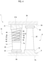
- FIG. 4 is an enlarged cross-sectional view of a main part of a steam turbine according to a second embodiment of the present disclosure.
- FIG. 5 is an enlarged cross-sectional view of a main part of a steam turbine according to a third embodiment of the present disclosure.
- FIG. 6 is an enlarged cross-sectional view of a main part of a steam turbine according to a fourth embodiment of the present disclosure.
- the steam turbine 1 includes a rotor 2 and a casing 3 .
- the rotor 2 has a rotating shaft 6 having a circular cross section extending along an axis Ac, and a plurality of rotor blade rows 7 provided on an outer peripheral surface of the rotating shaft 6 .
- the rotating shaft 6 is rotatable around the axis Ac.
- the plurality of rotor blade rows 7 are arranged at intervals in an axis Ac direction.
- Each rotor blade row 7 has a plurality of rotor blades 8 arranged in a circumferential direction of the axis Ac.
- the rotor blade 8 extends radially outward from the outer peripheral surface of the rotating shaft 6 . A detailed configuration of the rotor blade 8 will be described later.
- the casing 3 has a casing body 3 H that covers the rotor 2 from an outer peripheral side, and a plurality of stator blade rows 9 supported from the outer peripheral side and an inner peripheral side by an outer ring 21 (described later) and an inner ring 23 (described later) provided on an inner peripheral side of the casing body 3 H.
- the casing body 3 H has a tubular shape centered on the axis Ac.
- the plurality of stator blade rows 9 are arranged at intervals in the axis Ac direction.
- the steam turbine 1 includes the came number of rotor blade rows 7 as the stator blade rows 9 , and one rotor blade row 7 is located between a pair of the stator blade rows 9 adjacent to each other in the axis Ac direction.
- each stator blade row 9 has a plurality of stator blades 10 arranged, in the circumferential direction of the axis Ac.
- the stator blade 10 extends in a radial direction with respect to the axis Ac.
- a steam flow path 11 for taking high-temperature and high-pressure steam guided from an inlet pipe into the stage of the casing body 3 H is formed on one side of the casing body 3 H in the axis Ac direction.
- An exhaust hood 12 responsible for collecting a pressure of the steam is provided on the other side of the casing body 3 H in the axis Ac direction.
- the steam that has flowed into the steam flow path 11 flows through the stages in the casing body 3 H, then passes through the exhaust hood 12 , and is sent to a condenser (not shown).
- a side on which the steam flow path 11 is located as viewed from the exhaust hood 12 will be referred to as an upstream side in a flow direction of the steam.
- a side on which the exhaust hood 12 is located as viewed from the steam flow path 11 is referred to as a downstream side.
- the rotor blade 8 includes a platform 81 , a rotor blade body 82 , and a shroud 83 .
- the platform 81 is installed on the outer peripheral surface of the rotating shaft 6 (rotating shaft outer peripheral surface 6 A).
- the rotor blade body 82 is provided on an outer peripheral side of the platform 81 .
- the rotor blade body 82 extends in the radial direction and has a blade-shaped cross-sectional shape when viewed in the radial direction.
- the rotor blade body 82 is formed so that a dimension in the axis Ac direction gradually decreases from an inner side to an outer side in the radial direction.
- the shroud 83 is provided at an end portion on a radially outer side of the rotor blade body 82 .
- the shroud 83 has a substantially rectangular cross-sectional shape having the axis Ac direction as a longitudinal direction.
- An outer peripheral surface of the shroud 83 faces an inner peripheral surface (casing inner peripheral surface 3 A) of the casing body 3 H at an interval in the radial direction,
- the stator blade 10 has the outer ring 21 , a stator blade body 22 , and the inner ring 23 .
- the stator blade body 22 has a water-repellent region 30 , a hydrophilic region 40 , and a slit S.
- the outer ring 21 has an annular shape centered on the axis Ac.
- the outer ring 21 is supported by the casing body 3 H via a support member (not shown).
- the stator blade body 22 is fixed between the outer ring 21 and the inner ring 23 .
- the stator blade body 22 extends radially inward from an outer ring inner peripheral surface 21 A and has a blade-shaped cross-sectional shape when viewed in the radial direction.
- the stator blade body 22 extends in a direction intersecting the flow direction of the steam.
- a dimension of the stator blade body 22 in the axis Ac direction gradually decreases from the outer side to the inner side in the radial direction.
- the inner ring 23 is provided at an end portion on a radially inner side of the stator blades body 22 .
- the inner ring 23 has a substantially rectangular cross-sectional shape having the axis Ac direction as a longitudinal direction.
- An inner peripheral surface of the inner ring 23 faces the rotating shaft outer peripheral surface 6 A at an interval in the radial direction.
- the water-repellent region 30 , the hydrophilic region 40 , and the silt S are formed on a surface of the stator blade body 22 (more specifically, a surface facing the upstream side of both surfaces of the stator blade body 22 in a thickness direction: a pressure side).
- a surface facing the upstream side of both surfaces of the stator blade body 22 in a thickness direction: a pressure side it is desirable that the water-repellent region 30 is formed from an outer periphery-side end portion of the stator blade body 22 to a region of about 1 ⁇ 2 to 2 ⁇ 3 in the radial direction.
- the water-repellent region 30 is formed over an entire region from an upstream-side end edge (leading edge Le) to a downstream-side end edge (trailing edge Te) of the stator blade body 22 .
- the water-repellent, region 30 has higher water repellency than the hydrophilic region 40 (described later) on the surface of the stator blade body 22 .
- the wafer-repellent region 30 is formed by subjecting the surface of the stator blade body 22 to fine processing for improving water repellency or by attaching a water-repellent sheet to the surface.
- a contact angle of an adhered droplet can be 90° or more. It is sufficient that, the water-repellent region 30 at least has a difference in hydrophilicity from the hydrophilic region 40 . For this reason, it is also possible to adopt a configuration in which only the hydrophilic region 40 is formed on the surface of the stator blade body 22 and the water-repellent region 30 is not formed.
- the slit S is formed as a collecting portion C for collecting a liquid film that has flowed along the hydrophilic region 40 , which will be described later.
- the slit S extends along the trailing edge Te.
- the slit 3 is one or more elongated holes communicating with an inside of the stator blade body 22 . That is, the stator blade body 22 is hollow. It Is desirable that an internal space of the stator blade body 22 is brought into a negative pressure state by a device (not shown).
- a plurality of (for example, four) the hydrophilic regions 40 are formed in a portion of the stator blade body 22 from the leading edge Le to the slit S.
- the hydrophilic region 40 has relatively high hydrophilicity compared to the above-mentioned water-repellent region 30 and to regions other than the water-repellent region 30 . That is, in the hydrophilic region, the contact angle of the adhered droplet is smaller than a contact angle of a droplet adhering to the water-repellent region. Accordingly, the droplet a spread to fit into the surface of the hydrophilic region 40 and are held in a thin liquid film state.
- the plurality of hydrophilic regions 40 are arranged in the radial direction.
- a width (that is, radial dimension) of each of the hydrophilic regions 40 gradually increases from the upstream side (leading edge Le side) toward the downstream side (slit S side).
- an expansion ratio of the width of the hydrophilic region 40 is constant. That is, the figure shows an example in which both a radially outer end edge and a radially inner end edge of the hydrophilic region 40 extend linearly.
- the plurality of hydrophilic regions 40 are continuous. In other wards, the upstream-side end edge of the slit S is connected to the hydrophilic regions 40 over the entire region. In other words, the upstream-side end edge of the silt S does not come into contact with the water-repellent region 30 .
- the liquid film flows downstream and increases in thickness as the number of droplets continues to increase, a portion of the liquid film is torn off by the steam flow, or the liquid film that remains adhering to the stator blade row 9 scatters as coarse droplets from the trailing edge of the stator blade.
- the scattering droplets flow toward the downstream side while gradually accelerating due to the steam flow.
- erosion may occur on a surface of the rotor blade 8 .
- the collision of the droplets may hinder rotation of the rotor blade 8 (rotor 2 ), resulting in braking loss.
- the hydrophilic region 40 is formed on the surface of the stator blade body 22 as described above.
- the droplets adhering to the stator blade body 22 spread thinly to fit into the hydrophilic region 40 and form, a liquid film. Since there is a difference in hydrophilicity at a boundary between the hydrophilic region 40 and another portion, the liquid film is held inside the hydrophilic region 40 . This liquid film rides on the flow of the steam and flows toward the downstream side in the hydrophilic region 40 .
- the radial dimension of the hydrophilic region 40 gradually increases toward the downstream side. Therefore, an area of the liquid film expands in the hydrophilic region 40 as the liquid film flows toward the downstream side, and the liquid film becomes thinner. Accordingly, a surface of the liquid film becomes more stable than in a case where the liquid film is maintained thick. Therefore, waves are less likely to be generated on the surface of the liquid film, and a probability that the liquid film is torn off by the steam flow is reduced. As a result, the liquid film flows toward the downstream side along the hydrophilic region 40 , and is easily collected by the slit S serving as the collecting portion C.
- the generation of the coarse droplets that are torn off by the steam flow on an upstream side of the slit S and the coarse droplets that jump over the slit S and that scatter from the trailing edge of the stator blade body 22 can be Suppressed. Therefore, a probability that the droplets scatter toward the rotor blade 8 located on the downstream side of the stator blade 10 can be reduced.
- the plurality of hydrophilic regions 40 are arranged in plurality in the radial direction. Accordingly, the droplets can be guided to the hydrophilic region 40 in a wider range in the radial direction.
- a region and a path where a liquid film is formed on the surface of the stator blade body 22 are substantially constant, and the liquid film tends to be formed on a side closer to the outer side than the inner side in the radial direction (from the outer periphery-side end portion of the stator blade body 22 to the region of about 1 ⁇ 2 to 2 ⁇ 3 in the radial direction).
- an area of the hydrophilic regions 40 can be minimized. That is, although the water repellency of the surface on an inner peripheral side of the stator blade body 22 may be higher than that of the water-repellent region 30 , this causes excessive processing costs. Therefore, it is desirable that the water-repellent region 30 is formed only on the outer peripheral side on which the hydrophilic regions 40 are formed as described above. As described above, a manufacturing cost and a maintenance cost can be reduced compared to a case where the hydrophilic region 40 is formed in the entire stator blade body 22 .
- the hydrophilic region 40 extends from the leading edge Le of the stator blade body 22 to the slit 3 serving as the collecting portion C. Accordingly, the liquid film can be stably guided by the hydrophilic region 40 over the entire region from the leading edge Le of the stator blade body 22 to the collecting portion C, and the liquid film can be collected.
- the slit 8 serving as the collecting portion C is formed on the trailing edge Te side of the stator blade body 22 .
- the slit S makes it possible to more stably capture and collect the liquid film.
- the plurality of hydrophilic regions 40 are continuous.
- the end edge is connected to the hydrophilic regions 40 over the entire region. Accordingly, for example, compared to a case where a portion of the end edge is not connected to the hydrophilic region 40 , the amount of the liquid film that can be guided to the collecting portion C can be increased, and the liquid film can be more efficiently and stably captured and collected.
- a portion extending in the radial direction to the hydrophilic region 40 is defined as the water-repellent region 30 . Accordingly, a difference in hydrophilicity at a boundary between the hydrophilic region 40 and the water-repellent region 30 can be further increased. As a result, a probability that the liquid film adhering to the hydrophilic region 40 moves to the water-repellent region 30 side over the boundary can be reduced. That is, the liquid film is easily held inside the hydrophilic region 40 . As a result, a probability that the liquid film deviates from the hydrophilic region 40 is further reduced, and the liquid film can be more smoothly guided to the slit 3 serving as the collecting portion C.
- the first embodiment of the present disclosure has been described.
- various changes and modifications of the above-described configuration can be made without departing from the gist of the present disclosure.
- the configuration of the hydrophilic region 40 is not limited thereto, and it is also possible to adopt a configuration shown in FIG. 3 as another example.
- only one hydrophilic region 40 b is formed from the leading edge Le to the slit 3 .
- a width (radial dimension) of the hydrophilic region 40 b also gradually increases from the upstream side to the downstream side. Even with such a configuration, it is possible to obtain the same actions and effects as described above.
- a separation zone 50 is formed in each hydrophilic region 40 .
- the separation zone 50 has water repellency similarly to the water-repellent region 30 described above.
- the separation zone 50 extends in a triangular shape from a position downstream of the leading edge Le side in the hydrophilic region 40 toward the downstream side. More specifically, a radial dimension of the separation zone 50 gradually increases from the leading edge Le side toward the slit 5 side.
- the hydrophilic region 40 is partitioned into a plurality of (two) regions in the radial direction, and forms a pair of regions extending in a band shape from the upstream side to the downstream side. The pair of regions extend from the upstream side toward the downstream side so as to be separated from each other on both sides in the radial direction.
- the separation zone 50 is formed in the hydrophilic region 40 .
- a traveling direction of the liquid film in the hydrophilic region 40 can be more precisely controlled.
- the width (radial dimension) of the hydrophilic region 40 becomes relatively small, and a length thereof in an upstream-downstream direction becomes relatively large. Accordingly, when the liquid film is guided from the upstream side to the downstream side, a probability that the flow of the liquid film deviates in the radial direction is reduced, so that it is possible to more stably guide the droplets to the collecting portion C on the downstream side. Accordingly, the probability that the liquid film grows and scatters toward the rotor blade 8 on the downstream side can be further reduced.
- the second embodiment of the present disclosure has been described.
- various changes and modifications of the above-described configuration can be made without departing from the gist of the present disclosure.
- an example in which only one separation zone 50 is formed in one hydrophilic region 40 has been described.
- an aspect of the separation zone 50 is not limited thereto, and as another example, it is possible to form two or more separation zones 50 in each hydrophilic region 40 .
- a third embodiment of the present disclosure will be described with reference to FIG. 5 .
- Configurations similar to those in each of the above-described embodiments are assigned the same reference numerals, and detailed description thereof will be omitted.
- a shape of a hydrophilic region 40 c is different front that of each of the above-described embodiments.
- the slit S is not formed in the stator blade body 22 .
- the hydrophilic region 40 c extends from the leading edge Le of the stator blade body 22 toward the inner peripheral surface (outer ring inner peripheral surface 21 A) of the outer ring 21 . That is, the hydrophilic region 40 c extends radially outward from the upstream side toward the downstream side.
- the outer ring inner peripheral surface 21 A forms a collecting portion C that collects the liquid film that has flowed along the hydrophilic region 40 c .
- a width (radial dimension) gradually increases toward the downstream side (the outer ring inner peripheral surface 21 A side).
- a plurality (three as an example) of such hydrophilic regions 40 c are formed at intervals in the radial direction.
- the outer ring inner peripheral surface 21 A functions as the collecting portion C. That is, the droplets adhering to the stator blade body 22 form a liquid film in the hydrophilic region 40 c , and then flow toward the outer peripheral side and flow to the outer ring inner peripheral surface 21 A. Accordingly, the flow of the liquid film toward the downstream side in the flow direction (main flow direction) of the steam is reduced, and the probability that the droplets scatter toward the rotor blade B on the downstream side can be further reduced. Accordingly, the occurrence of erosion in the rotor blade 8 can be suppressed.
- a hydrophilic region 40 d has a first region A 1 having the same configuration as the hydrophilic region 40 c described in the third embodiment, and a second region A 2 formed on an inner peripheral side of the first region A 1 .
- the first region A 1 extends from the leading edge Le toward the outer ring inner peripheral surface 21 A.
- the second region A 2 extends radially inward from the upstream side toward the downstream side.
- a plurality of (three as an example) the second regions A 2 are arranged at intervals in the radial direction.
- an upstream-side end portion of the second region A 2 is located in the middle of the first region A 1 in an extending direction (a direction including a component in the axis Ac direction).
- a downstream-side end portion of the second region A 2 is located at the trailing edge Te.
- the liquid film can be guided toward the outer ring 21 by the first region A 1 , and a component of the droplets that cannot be completely captured by the first region A 1 or a component deviating from the first region A 1 can be captured by the second region A 2 .
- the second region A 2 extends radially inward toward the downstream side. Accordingly, a probability that the liquid droplet or the liquid film stays in a central portion of the stator blade body 22 in the radial direction is reduced. Even in a case where the liquid film in the second region A 2 is torn off and coarse droplets are generated, the coarse droplets can scatter toward an inner periphery-side portion of the rotor blade 8 on the downstream side.
- an inner peripheral side of the rotor blade 8 has a lower circumferential speed than that of an outer periphery-side end portion, thereof, a relative speed with respect to the coarse droplets can be minimized. As a result, even in a case where the coarse droplets collide with the inner peripheral side of the rotor blade 3 , it is possible to minimize the probability of erosion.
- the turbine stator blade (stator blade 10 ) and the strain turbine 1 described in each embodiment are identified as follows, for example.
- the turbine stator blade (stator blade 10 ) includes: the stator blade body 22 extending in the radial direction intersecting the flow direction of the steam; the hydrophilic region 40 , 40 b , 40 c , or 40 d that is formed on the surface of the stator blade body 22 , has higher hydrophilicity than other portions, and has a radial dimension gradually increasing toward the downstream side in the flow direction; and the collecting portion C that is provided on a downstream side of the hydrophilic region 40 , 40 b , 40 c , or 40 d and that collects a liquid film flowing along the hydrophilic region 40 , 40 b , 40 c , or 40 d.
- the hydrophilic region 40 , 40 b , 40 c , or 40 d is formed on the surface of the stator blade body 22 . Accordingly, the droplets adhering to the stator blade body 22 spread thinly to fit into the hydrophilic region 40 , 40 b , 40 c , or 40 d , and form a liquid film, Since there is a difference in hydrophilicity at the boundary between the hydrophilic region 40 , 40 b , 40 c , or 40 d and another portion, the liquid film is held inside the hydrophilic region 40 . This liquid film rides on the flow of the stream and flows toward the downstream side in the hydrophilic region 40 , 40 b , 40 c , or 40 d .
- the radial dimension of the hydrophilic region 40 , 40 b , 40 c , or 40 d gradually increases toward the downstream side. Therefore, the area of the liquid film expands in the hydrophilic region 40 , 40 b , 40 c , or 40 d as the liquid, film flows toward the downstream side, and the liquid film becomes thinner. Accordingly, compared to a case where the liquid film is maintained thick, a probability that the liquid film is torn off by the flow of the steam is reduced. As a result, the liquid film cart be efficiently collected by the collecting portion C, and the probability that the droplets scatter toward the turbine rotor blade (rotor blade 8 ) located on the downstream side of the turbine stator blade can be reduced.
- the plurality of hydrophilic regions 40 , 40 c , or 40 d are arranged in plurality in the redial direction. Accordingly, the droplets can be guided to the hydrophilic region 40 , 40 c , or 40 d in a wider range in the radial direction.
- the steam turbine 1 is generally continuously operated under the rated conditions, a region and a path where a liquid film is formed on the surface of the stator blade body 22 are substantially constant.
- the area of the hydrophilic region 40 , 40 c , or 40 d can be minimized. Accordingly, the manufacturing cost and the maintenance cost can be reduced compared to the case where the hydrophilic region 40 , 40 c , or 40 d is formed in the entire stator blade body 22 .
- the hydrophilic region 40 , 40 b , or 40 c extends from, the leading edge Le of the stator blade body 22 to the collecting portion C.
- the hydrophilic region 40 , 40 b , or 40 c extends from the leading edge Le of the stator blade body 22 to the collecting portion C. Accordingly, the liquid film can be stably guided by the hydrophilic region 40 , 40 b , or 40 c (or the first region A 1 of the hydrophilic region 40 d ) over the entire region from the leading edge Le or the stator blade body 22 to the collecting portion C, and the liquid film can be more efficiently collected.
- the turbine stator blade according to a fourth aspect further includes: the separation zone 50 that extends from the position downstream of the leading edge Le side in the hydrophilic region 40 toward the downstream side to partition the hydrophilic region 40 into a plurality of regions.
- the separation zone 50 is formed in the hydrophilic region 40 .
- the traveling direction of the liquid film in the hydrophilic region 40 can be more precisely controlled.
- the width (radial dimension) of the hydrophilic region 40 becomes relatively small, and the length thereof in the upstream-downstream direction becomes relatively large. Accordingly, when the liquid film is guided from the upstream side to the downstream side, the probability that, the liquid film deviates in the radial direction is reduced, so that it is possible to more stably guide the droplets to the collecting portion C on the downstream side.
- the collecting portion C is the slit S that is formed on the trailing edge Te side of the stator blade body 22 , extends along the trailing edge Te, and communicates with the inside of the stator blade body 22 .
- the slit S serving as the collecting portion C is formed on the trailing edge Te side of the stator blade body 22 .
- the slit S makes it possible to more stably capture and collect the liquid film.
- a plurality of the hydrophilic regions 40 arranged in the radial direction are included, and at the upstream-side end edge of the slit S, the plurality of hydrophilic regions 40 are continuous.
- the plurality of hydrophilic regions 40 are continuous.
- the end edge is connected to the hydrophilic regions 40 over the entire region. Accordingly, for example, compared to a case where a portion of the end edge is not connected to the hydrophilic region 40 , the amount of the liquid film that does not reach the collecting portion C is reduced, and the liquid film can be more efficiently and stably captured and collected.
- the turbine stator blade according to a seventh aspect further includes: the outer ring 21 provided on the outer peripheral side of the stator blade body 22 , in which the collecting portion C is the inner peripheral surface (cuter ring inner peripheral surface 21 A) of the outer ring 21 .
- the inner peripheral surface of the outer ring 21 functions as the collecting portion C. That is, the droplets adhering to the stator blade body 22 form a liquid film in the hydrophilic region 40 c (or the first region A 1 of the hydrophilic region 40 d ), and then flow toward the outer peripheral side and flow to the inner peripheral surface of the outer ring 21 . Accordingly, the flow of the liquid film toward the downstream side in the flow direction (main flow direction) of the steam is reduced, and the probability that the droplets scatter toward the turbine rotor blade on the downstream side can be further reduced.
- the hydrophilic region 40 c (or the first region A 1 of the hydrophilic region 40 d ) extends radially outward from the upstream side toward the downstream side, and is connected to the inner peripheral surface of the outer ring 21 .
- the liquid film can be stably and smoothly guided to the inner peripheral surface of the outer ring 21 along the hydrophilic region 40 c (or the first region A 1 of the hydrophilic region 40 d ).
- the hydrophilic region 40 d has the first region A 1 extending toward the inner peripheral surface of the outer ring 21 , and the second region A 2 that is formed on the inner peripheral side of the first region A 1 and that extends radially inward from the upstream side toward the downstream side.
- the liquid film can be guided toward the cuter ring 21 by the first region A 1 , and a component of the droplets that cannot be completely captured by the first region A 3 , caw be captured by the second region A 2 .
- the second region A 2 extends radially inward toward the downstream side. Accordingly, the probability that the liquid film stays in the central portion oil the stator blade body 22 in the radial direction is reduced. Even in a case where coarse droplets are generated on the trailing edge side due to the liquid film of the second region A 2 , the coarse droplets can scatter toward the inner periphery-side portion of the turbine rotor blade on the downstream side.
- the inner peripheral side of the turbine rotor blade has a lower circumferential speed than that of the outer periphery-side end portion thereof, a relative speed with respect to the coarse droplets cart be minimized. As a result, even in a case where the coarse droplets collide with the inner peripheral side of the turbine rotor blade, it is possible to minimize the probability of erosion.
- the portion of the surface of the stator blade body 22 extending to at least the hydrophilic region 40 , 40 b , 40 c , or 40 d is the water-repellent region 30 having higher water repellency than the hydrophilic: region 40 , 40 b , 40 c , or 40 d.
- the portion extending to the hydrophilic region 40 , 40 b , 40 c , or 40 d is defined as the water-repellent region 30 . Accordingly, the difference in hydrophilicity at the boundary between the hydrophilic region 40 , 40 b , 40 c , or 40 d and the water-repellent region 30 can be further increased. As a result, the liquid film is easily held inside the hydrophilic region 40 , 40 b , 40 c , or 40 d , and the probability that the liquid film deviates from the hydrophilic region 40 , 40 b , 40 c , or 40 d can be further reduced.
- the steam turbine 1 includes: the rotating shaft 6 that is rotatable around the axis Ac; a plurality of turbine rotor blades (rotor blades 8 ) arranged on the outer peripheral surface (rotating shaft outer peripheral surface 6 A) of the rotating shaft 6 in the circumferential direction with respect to the axis Ac direction; the casing body 3 B that covers the rotating shaft 6 and the turbine rotor blade from the outer peripheral side; and a plurality of the turbine stator blades (stator blades 10 ) which are arranged on the inner peripheral surface of the casing body 38 in the circumferential direction with respect to the axis Ac and which are provided adjacent to the turbine rotor blades in the axis Ac direction.
- the present disclosure relates to a turbine stator blade and a steam turbine. According to the present disclosure, it is possible to provide a turbine stator blade and a steam turbine capable of further reducing growth of a liquid film and facilitating efficient collection of the liquid film.
Landscapes
- Engineering & Computer Science (AREA)
- Mechanical Engineering (AREA)
- General Engineering & Computer Science (AREA)
- Physics & Mathematics (AREA)
- Fluid Mechanics (AREA)
- Chemical & Material Sciences (AREA)
- Materials Engineering (AREA)
- Turbine Rotor Nozzle Sealing (AREA)
Abstract
Description
-
- [PTL 1] Japanese Unexamined Patent Application Publication No. 2017-106451
-
- 1: Steam turbine
- 2: Rotor
- 3: Casing
- 3A: Casing inner peripheral surface
- 3H: Casing body
- 6: Rotating shaft
- 6A: Rotating shaft outer peripheral surface
- 7: Rotor blade row
- 8: Rotor blade (turbine sot or: blade)
- 9: Stator blade row
- 10: Stator blade (turbine stator blade)
- 11: Steam flow path
- 12: Exhaust hood
- 21: Outer ring
- 22A: Outer ring inner peripheral surface
- 22: Stator blade body
- 23: Inner ring
- 30: Water-repellent region
- 40, 40 b, 40 c, 40 d: Hydrophilic region
- 50: Separation zone
- 81: Platform
- 82: Rotor blade body
- 83: Shroud
- A1: First region
- A2: Second region
- Ac: Axis
- C: Collecting portion
- Le: Leading edge
- S: Slit
- Te: Trailing edge
Claims (10)
Applications Claiming Priority (3)
| Application Number | Priority Date | Filing Date | Title |
|---|---|---|---|
| JP2020136246 | 2020-08-12 | ||
| JP2020-136246 | 2020-08-12 | ||
| PCT/JP2021/025171 WO2022034756A1 (en) | 2020-08-12 | 2021-07-02 | Stationary turbine blade and steam turbine |
Related Parent Applications (1)
| Application Number | Title | Priority Date | Filing Date |
|---|---|---|---|
| PCT/JP2021/025171 Continuation WO2022034756A1 (en) | 2020-08-12 | 2021-07-02 | Stationary turbine blade and steam turbine |
Publications (2)
| Publication Number | Publication Date |
|---|---|
| US20230167746A1 US20230167746A1 (en) | 2023-06-01 |
| US12221900B2 true US12221900B2 (en) | 2025-02-11 |
Family
ID=80247152
Family Applications (1)
| Application Number | Title | Priority Date | Filing Date |
|---|---|---|---|
| US18/096,129 Active US12221900B2 (en) | 2020-08-12 | 2023-01-12 | Stationary turbine blade and steam turbine |
Country Status (6)
| Country | Link |
|---|---|
| US (1) | US12221900B2 (en) |
| JP (1) | JP7429296B2 (en) |
| KR (1) | KR102865921B1 (en) |
| CN (1) | CN116137878B (en) |
| DE (1) | DE112021004233T5 (en) |
| WO (1) | WO2022034756A1 (en) |
Cited By (1)
| Publication number | Priority date | Publication date | Assignee | Title |
|---|---|---|---|---|
| US20260078675A1 (en) * | 2022-11-11 | 2026-03-19 | Mitsubishi Heavy Industries, Ltd. | Steam turbine blade, steam turbine, and method for manufacturing steam turbine blade |
Citations (4)
| Publication number | Priority date | Publication date | Assignee | Title |
|---|---|---|---|---|
| JPS6480705A (en) * | 1987-09-24 | 1989-03-27 | Hitachi Ltd | Stationary blade construction for steam turbine |
| US20070101719A1 (en) | 2005-10-31 | 2007-05-10 | Kabushiki Kaisha Toshiba | Steam turbine and hydrophilic coating material used therefor |
| JP2007309235A (en) | 2006-05-19 | 2007-11-29 | Toshiba Corp | Turbine blade |
| US20170167301A1 (en) | 2015-12-11 | 2017-06-15 | General Electric Company | Steam turbine, a steam turbine nozzle, and a method of managing moisture in a steam turbine |
Family Cites Families (8)
| Publication number | Priority date | Publication date | Assignee | Title |
|---|---|---|---|---|
| CN102454439B (en) * | 2010-10-19 | 2015-07-15 | 株式会社东芝 | Steam turbine plant |
| CN102454438B (en) * | 2010-10-19 | 2015-03-25 | 株式会社东芝 | Steam turbine plant |
| JP2014084744A (en) * | 2012-10-20 | 2014-05-12 | Mitsui Eng & Shipbuild Co Ltd | Dust adhesion prevention device for stator blade of furnace top pressure recovery turbine |
| JP2017020443A (en) * | 2015-07-13 | 2017-01-26 | 株式会社東芝 | Nozzle for steam turbine and steam turbine provided with the nozzle |
| JP6637455B2 (en) * | 2017-02-10 | 2020-01-29 | 三菱日立パワーシステムズ株式会社 | Steam turbine |
| JP6730245B2 (en) * | 2017-11-17 | 2020-07-29 | 三菱日立パワーシステムズ株式会社 | Turbine nozzle and axial turbine having this turbine nozzle |
| JP7003946B2 (en) | 2019-02-26 | 2022-01-21 | オムロン株式会社 | Air purge unit |
| JP7179651B2 (en) * | 2019-02-27 | 2022-11-29 | 三菱重工業株式会社 | Turbine stator blades and steam turbines |
-
2021
- 2021-07-02 DE DE112021004233.5T patent/DE112021004233T5/en active Pending
- 2021-07-02 KR KR1020237001527A patent/KR102865921B1/en active Active
- 2021-07-02 WO PCT/JP2021/025171 patent/WO2022034756A1/en not_active Ceased
- 2021-07-02 CN CN202180061201.0A patent/CN116137878B/en active Active
- 2021-07-02 JP JP2022542598A patent/JP7429296B2/en active Active
-
2023
- 2023-01-12 US US18/096,129 patent/US12221900B2/en active Active
Patent Citations (7)
| Publication number | Priority date | Publication date | Assignee | Title |
|---|---|---|---|---|
| JPS6480705A (en) * | 1987-09-24 | 1989-03-27 | Hitachi Ltd | Stationary blade construction for steam turbine |
| US20070101719A1 (en) | 2005-10-31 | 2007-05-10 | Kabushiki Kaisha Toshiba | Steam turbine and hydrophilic coating material used therefor |
| JP2007120478A (en) | 2005-10-31 | 2007-05-17 | Toshiba Corp | Steam turbine and hydrophilic coating material thereof |
| US8132414B2 (en) * | 2005-10-31 | 2012-03-13 | Kabushiki Kaisha Toshiba | Steam turbine and hydrophilic coating material used therefor |
| JP2007309235A (en) | 2006-05-19 | 2007-11-29 | Toshiba Corp | Turbine blade |
| US20170167301A1 (en) | 2015-12-11 | 2017-06-15 | General Electric Company | Steam turbine, a steam turbine nozzle, and a method of managing moisture in a steam turbine |
| JP2017106451A (en) | 2015-12-11 | 2017-06-15 | ゼネラル・エレクトリック・カンパニイ | Steam turbine, steam turbine nozzle, and method for managing moisture in a steam turbine |
Non-Patent Citations (3)
| Title |
|---|
| International Search Report issued Sep. 7, 2021 in International Application No. PCT/JP2021/025171, with English translation. |
| Machine Translation of JP-01080705-A [retrieved on Mar. 1, 2024]. Retrieved from: Espacenet. (Year: 2024). * |
| Written Opinion of the International Searching Authority issued Sep. 7, 2021 in International Application No. PCT/JP2021/025171, with English translation. |
Cited By (1)
| Publication number | Priority date | Publication date | Assignee | Title |
|---|---|---|---|---|
| US20260078675A1 (en) * | 2022-11-11 | 2026-03-19 | Mitsubishi Heavy Industries, Ltd. | Steam turbine blade, steam turbine, and method for manufacturing steam turbine blade |
Also Published As
| Publication number | Publication date |
|---|---|
| CN116137878B (en) | 2026-01-13 |
| JP7429296B2 (en) | 2024-02-07 |
| WO2022034756A1 (en) | 2022-02-17 |
| JPWO2022034756A1 (en) | 2022-02-17 |
| KR20230023783A (en) | 2023-02-17 |
| KR102865921B1 (en) | 2025-09-26 |
| CN116137878A (en) | 2023-05-19 |
| DE112021004233T5 (en) | 2023-06-07 |
| US20230167746A1 (en) | 2023-06-01 |
Similar Documents
| Publication | Publication Date | Title |
|---|---|---|
| EP2204535B1 (en) | Turbine blade platform contours | |
| EP2708699B1 (en) | Steam turbine stationary blade and steam turbine | |
| JP7292421B2 (en) | Turbine stator vane, turbine stator vane assembly, and steam turbine | |
| JP7179651B2 (en) | Turbine stator blades and steam turbines | |
| EP2615245B1 (en) | Film cooled turbine airfoil having trench segments on the exterior surface | |
| JP7179652B2 (en) | Turbine stator blades and steam turbines | |
| CN101403321A (en) | Axial flow turbine and stage structure thereof | |
| US12221900B2 (en) | Stationary turbine blade and steam turbine | |
| JP2016166569A (en) | Steam turbine | |
| CN106256994B (en) | Axial flow turbine | |
| JP2007309235A (en) | Turbine blade | |
| JP4184565B2 (en) | Steam turbine nozzle and steam turbine using the steam turbine nozzle | |
| US12037927B2 (en) | Turbine stator vane and steam turbine | |
| JP5868774B2 (en) | Steam turbine and steam turbine blades | |
| EP3967853B1 (en) | Turbine blade with non-axisymmetric forward feature | |
| US12037917B2 (en) | Steam turbine | |
| CN117027962B (en) | Steam turbine and its stator blades | |
| CN114542193B (en) | Steam turbine rotor blade | |
| JP2025021737A (en) | Steam turbine |
Legal Events
| Date | Code | Title | Description |
|---|---|---|---|
| AS | Assignment |
Owner name: MITSUBISHI HEAVY INDUSTRIES, LTD., JAPAN Free format text: ASSIGNMENT OF ASSIGNORS INTEREST;ASSIGNORS:DUAN, CHONGFEI;MIZUMI, SHUNSUKE;TABATA, SOICHIRO;AND OTHERS;REEL/FRAME:062361/0358 Effective date: 20230106 |
|
| FEPP | Fee payment procedure |
Free format text: ENTITY STATUS SET TO UNDISCOUNTED (ORIGINAL EVENT CODE: BIG.); ENTITY STATUS OF PATENT OWNER: LARGE ENTITY |
|
| AS | Assignment |
Owner name: MITSUBISHI HEAVY INDUSTRIES, LTD., JAPAN Free format text: CORRECTIVE ASSIGNMENT TO CORRECT THE DOCKET NUMBER PREVIOUSLY RECORDED AT REEL: 062361 FRAME: 0358. ASSIGNOR(S) HEREBY CONFIRMS THE ASSIGNMENT;ASSIGNORS:DUAN, CHONGFEI;MIZUMI, SHUNSUKE;TABATA, SOICHIRO;AND OTHERS;REEL/FRAME:062514/0951 Effective date: 20230106 |
|
| STPP | Information on status: patent application and granting procedure in general |
Free format text: DOCKETED NEW CASE - READY FOR EXAMINATION |
|
| STPP | Information on status: patent application and granting procedure in general |
Free format text: NON FINAL ACTION MAILED |
|
| STPP | Information on status: patent application and granting procedure in general |
Free format text: RESPONSE TO NON-FINAL OFFICE ACTION ENTERED AND FORWARDED TO EXAMINER |
|
| STPP | Information on status: patent application and granting procedure in general |
Free format text: FINAL REJECTION MAILED |
|
| STPP | Information on status: patent application and granting procedure in general |
Free format text: DOCKETED NEW CASE - READY FOR EXAMINATION |
|
| STPP | Information on status: patent application and granting procedure in general |
Free format text: NOTICE OF ALLOWANCE MAILED -- APPLICATION RECEIVED IN OFFICE OF PUBLICATIONS |
|
| ZAAB | Notice of allowance mailed |
Free format text: ORIGINAL CODE: MN/=. |
|
| STPP | Information on status: patent application and granting procedure in general |
Free format text: PUBLICATIONS -- ISSUE FEE PAYMENT VERIFIED |
|
| STCF | Information on status: patent grant |
Free format text: PATENTED CASE |