US12206353B2 - Drive control apparatus for brushless motor and related device - Google Patents
Drive control apparatus for brushless motor and related device Download PDFInfo
- Publication number
- US12206353B2 US12206353B2 US18/041,765 US202218041765A US12206353B2 US 12206353 B2 US12206353 B2 US 12206353B2 US 202218041765 A US202218041765 A US 202218041765A US 12206353 B2 US12206353 B2 US 12206353B2
- Authority
- US
- United States
- Prior art keywords
- brushless motor
- circuit
- drive
- period
- resistor
- Prior art date
- Legal status (The legal status is an assumption and is not a legal conclusion. Google has not performed a legal analysis and makes no representation as to the accuracy of the status listed.)
- Active
Links
- 238000012544 monitoring process Methods 0.000 claims description 104
- 230000007274 generation of a signal involved in cell-cell signaling Effects 0.000 claims description 67
- 239000003990 capacitor Substances 0.000 claims description 16
- 238000000034 method Methods 0.000 description 49
- 230000008569 process Effects 0.000 description 49
- 238000010586 diagram Methods 0.000 description 18
- 230000008859 change Effects 0.000 description 11
- 230000006870 function Effects 0.000 description 11
- 238000012545 processing Methods 0.000 description 8
- 230000009286 beneficial effect Effects 0.000 description 7
- 230000005540 biological transmission Effects 0.000 description 7
- 230000007423 decrease Effects 0.000 description 7
- 230000004044 response Effects 0.000 description 6
- 238000004804 winding Methods 0.000 description 6
- 230000000694 effects Effects 0.000 description 5
- 238000005265 energy consumption Methods 0.000 description 5
- 238000001914 filtration Methods 0.000 description 3
- 238000013528 artificial neural network Methods 0.000 description 2
- 238000013461 design Methods 0.000 description 2
- 238000005516 engineering process Methods 0.000 description 2
- 230000001960 triggered effect Effects 0.000 description 2
- 230000003321 amplification Effects 0.000 description 1
- 238000002474 experimental method Methods 0.000 description 1
- 230000014509 gene expression Effects 0.000 description 1
- 230000007774 longterm Effects 0.000 description 1
- 230000005405 multipole Effects 0.000 description 1
- 238000003199 nucleic acid amplification method Methods 0.000 description 1
- 238000011160 research Methods 0.000 description 1
- 238000004904 shortening Methods 0.000 description 1
Images


Classifications
-
- H—ELECTRICITY
- H02—GENERATION; CONVERSION OR DISTRIBUTION OF ELECTRIC POWER
- H02P—CONTROL OR REGULATION OF ELECTRIC MOTORS, ELECTRIC GENERATORS OR DYNAMO-ELECTRIC CONVERTERS; CONTROLLING TRANSFORMERS, REACTORS OR CHOKE COILS
- H02P6/00—Arrangements for controlling synchronous motors or other dynamo-electric motors using electronic commutation dependent on the rotor position; Electronic commutators therefor
- H02P6/08—Arrangements for controlling the speed or torque of a single motor
-
- H—ELECTRICITY
- H02—GENERATION; CONVERSION OR DISTRIBUTION OF ELECTRIC POWER
- H02P—CONTROL OR REGULATION OF ELECTRIC MOTORS, ELECTRIC GENERATORS OR DYNAMO-ELECTRIC CONVERTERS; CONTROLLING TRANSFORMERS, REACTORS OR CHOKE COILS
- H02P29/00—Arrangements for regulating or controlling electric motors, appropriate for both AC and DC motors
- H02P29/02—Providing protection against overload without automatic interruption of supply
- H02P29/024—Detecting a fault condition, e.g. short circuit, locked rotor, open circuit or loss of load
- H02P29/027—Detecting a fault condition, e.g. short circuit, locked rotor, open circuit or loss of load the fault being an over-current
-
- H—ELECTRICITY
- H02—GENERATION; CONVERSION OR DISTRIBUTION OF ELECTRIC POWER
- H02P—CONTROL OR REGULATION OF ELECTRIC MOTORS, ELECTRIC GENERATORS OR DYNAMO-ELECTRIC CONVERTERS; CONTROLLING TRANSFORMERS, REACTORS OR CHOKE COILS
- H02P29/00—Arrangements for regulating or controlling electric motors, appropriate for both AC and DC motors
- H02P29/02—Providing protection against overload without automatic interruption of supply
- H02P29/032—Preventing damage to the motor, e.g. setting individual current limits for different drive conditions
-
- H—ELECTRICITY
- H02—GENERATION; CONVERSION OR DISTRIBUTION OF ELECTRIC POWER
- H02P—CONTROL OR REGULATION OF ELECTRIC MOTORS, ELECTRIC GENERATORS OR DYNAMO-ELECTRIC CONVERTERS; CONTROLLING TRANSFORMERS, REACTORS OR CHOKE COILS
- H02P29/00—Arrangements for regulating or controlling electric motors, appropriate for both AC and DC motors
- H02P29/40—Regulating or controlling the amount of current drawn or delivered by the motor for controlling the mechanical load
-
- H—ELECTRICITY
- H02—GENERATION; CONVERSION OR DISTRIBUTION OF ELECTRIC POWER
- H02P—CONTROL OR REGULATION OF ELECTRIC MOTORS, ELECTRIC GENERATORS OR DYNAMO-ELECTRIC CONVERTERS; CONTROLLING TRANSFORMERS, REACTORS OR CHOKE COILS
- H02P6/00—Arrangements for controlling synchronous motors or other dynamo-electric motors using electronic commutation dependent on the rotor position; Electronic commutators therefor
- H02P6/20—Arrangements for starting
-
- H—ELECTRICITY
- H02—GENERATION; CONVERSION OR DISTRIBUTION OF ELECTRIC POWER
- H02P—CONTROL OR REGULATION OF ELECTRIC MOTORS, ELECTRIC GENERATORS OR DYNAMO-ELECTRIC CONVERTERS; CONTROLLING TRANSFORMERS, REACTORS OR CHOKE COILS
- H02P6/00—Arrangements for controlling synchronous motors or other dynamo-electric motors using electronic commutation dependent on the rotor position; Electronic commutators therefor
- H02P6/24—Arrangements for stopping
-
- H—ELECTRICITY
- H02—GENERATION; CONVERSION OR DISTRIBUTION OF ELECTRIC POWER
- H02P—CONTROL OR REGULATION OF ELECTRIC MOTORS, ELECTRIC GENERATORS OR DYNAMO-ELECTRIC CONVERTERS; CONTROLLING TRANSFORMERS, REACTORS OR CHOKE COILS
- H02P6/00—Arrangements for controlling synchronous motors or other dynamo-electric motors using electronic commutation dependent on the rotor position; Electronic commutators therefor
- H02P6/28—Arrangements for controlling current
-
- H—ELECTRICITY
- H02—GENERATION; CONVERSION OR DISTRIBUTION OF ELECTRIC POWER
- H02P—CONTROL OR REGULATION OF ELECTRIC MOTORS, ELECTRIC GENERATORS OR DYNAMO-ELECTRIC CONVERTERS; CONTROLLING TRANSFORMERS, REACTORS OR CHOKE COILS
- H02P2209/00—Indexing scheme relating to controlling arrangements characterised by the waveform of the supplied voltage or current
- H02P2209/09—PWM with fixed limited number of pulses per period
Definitions
- This application relates to the field of drive control technologies, and in particular, to a drive control apparatus for a brushless motor and a related device.
- An electronic device such as a mobile phone, a tablet, or a smart watch, usually has a vibration function.
- a mobile phone vibrates to notify a user that there is a new message.
- the vibration function of the electronic device is implemented by using a brushless motor.
- a processor of the electronic device controls the brushless motor to be turned on, the brushless motor generates vibration.
- the processor of the electronic device controls the brushless motor to be turned off, the brushless motor stops vibration.
- a turn-off response time in a process in which a processor controls a brushless motor to be turned off is relatively long, that is, a time period from a moment at which the processor starts to control the brushless motor to be turned off to a moment at which the brushless motor actually stops vibration is relatively long, power consumption is relatively high, and vibration of a mobile phone cannot be quickly stopped.
- This application provides a drive control apparatus for a brushless motor and a related device, to resolve a problem that a brushless motor cannot be quickly turned off.
- this application discloses a drive control apparatus for a brushless motor and a related device.
- the drive control apparatus for a brushless motor includes: a motor drive circuit, where the motor drive circuit is connected to the brushless motor; and a discharge circuit, where the discharge circuit is connected to the brushless motor and the motor drive circuit.
- the motor drive circuit is configured to: in a turn-off period of the brushless motor, stop supplying power to the brushless motor, and output an induced current generated by the brushless motor to the discharge circuit.
- the discharge circuit is configured to: in the turn-off period of the brushless motor, receive the induced current, and apply work by using the induced current, to consume electric energy of the brushless motor.
- the induced current generated by the brushless motor may be output to the discharge circuit, so that the discharge circuit can apply work by using the induced current, to consume the electric energy of the brushless motor.
- the brushless motor can use up stored energy as soon as possible, so that duration required for completely turning off the brushless motor is shortened, and the brushless motor is quickly turned off.
- the discharge circuit is configured to: in the turn-off period of the brushless motor, receive the induced current under control of a first drive signal, and apply work by using the induced current, to consume the electric energy of the brushless motor.
- the discharge circuit is configured to: in the turn-off period of the brushless motor, receive the induced current under control of the first drive signal, and enable the induced current to flow through a discharge component, to apply work by using the discharge component.
- the discharge component can convert the electric energy into internal energy for consumption.
- the discharge circuit is further configured to: under control of the first drive signal, not apply work by using the discharge component in each of a turn-on period and a stable working period of the brushless motor.
- the electrical energy of the brushless motor is used to maintain running, and does not need to be consumed by the discharge component by applying work.
- the discharge circuit includes a first switching transistor and the discharge component.
- a first end of the first switching transistor is connected to one end of the discharge component, a second end of the first switching transistor is connected to a first end of the brushless motor, and a control end of the first switching transistor receives the first drive signal.
- the first drive signal controls the first switching transistor to be conducted in the turn-off period of the brushless motor, the other end of the discharge component is connected to a second end of the brushless motor, and a common end between the discharge component and the brushless motor is grounded.
- the discharge component is a first resistor.
- the motor drive circuit is configured to: in the turn-off period of the brushless motor, stop, under control of a second drive signal, supplying power to the brushless motor, and output the induced current generated by the brushless motor to the discharge circuit.
- the motor drive circuit is further configured to: in the stable working period of the brushless motor, when the second drive signal is in a first level state, supply power to the brushless motor; or when the second drive signal is in a second level state, stop supplying power to the brushless motor, and output the induced current generated by the brushless motor to a freewheeling circuit.
- the second drive signal in the stable working period is a pulse width modulation signal.
- the first level state may be a low-level state
- the second level state may be a high-level state
- the first level state may be a high-level state
- the second level state may be a low-level state. Because the second drive signal is a pulse width modulation signal, and is not always in a same level state, power is not always supplied to the brushless motor, and power consumption of the brushless motor in the stable working period is relatively low.
- the motor drive circuit is further configured to continuously provide an overvoltage turn-on voltage for the brushless motor under control of the second drive signal in the turn-on period of the brushless motor.
- the overvoltage turn-on voltage is continuously provided for the brushless motor under control of the second drive signal, so that the brushless motor can be quickly turned on in an overvoltage state. In this way, duration of the turn-on period is reduced, and the brushless motor is quickly turned on.
- the motor drive circuit includes a second switching transistor and a second resistor.
- a first end of the second switching transistor is connected to one end of the second resistor, a second end of the second switching transistor is connected to the first end of the brushless motor, and a control end of the second switching transistor receives the second drive signal.
- the second end of the brushless motor is grounded, and the second drive signal controls the second switching transistor to be cut off in the turn-off period.
- the other end of the second resistor receives a supply voltage.
- the drive control apparatus for the brushless motor further includes the freewheeling circuit, and the freewheeling circuit is connected to the brushless motor and the motor drive circuit.
- the freewheeling circuit is configured to perform freewheeling on the induced current in the brushless motor under control of a third drive signal in the stable working period of the brushless motor.
- the freewheeling circuit can perform freewheeling on the induced current in the brushless motor under control of the third drive signal in the stable working period of the brushless motor, so that the brushless motor can maintain a stable working state, and a case in which the brushless motor stops running in the stable working period because the motor drive circuit stops supplying power to the brushless motor does not occur.
- the freewheeling circuit includes a third switching transistor and a diode.
- a first end of the third switching transistor is connected to a cathode of the diode, a second end of the third switching transistor is connected to the first end of the brushless motor, a control end of the third switching transistor receives the third drive signal, an anode of the diode is connected to the second end of the brushless motor, and a common end between the diode and the brushless motor is grounded.
- the drive control apparatus for the brushless motor further includes a drive signal generation circuit, where the drive signal generation circuit is connected to the discharge circuit.
- the drive signal generation circuit is configured to: receive a first control signal, and generate and output the first drive signal under control of the first control signal.
- the drive signal generation circuit is configured to: receive the first control signal, and invert the first control signal to obtain a second control signal; and generate and output the first drive signal under control of the second control signal.
- the drive signal generation circuit includes a third resistor, a fourth resistor, a fourth switching transistor, a first capacitor, and a phase inverter.
- One end of the third resistor receives the supply voltage, and the other end of the third resistor is connected to a second end of the fourth switching transistor.
- a first end of the fourth switching transistor is grounded, and a control end of the fourth switching transistor receives the second control signal.
- One end of the fourth resistor receives the first control signal, the other end of the fourth resistor is connected to one end of the first capacitor, and a common end between the third resistor and the fourth switching transistor outputs the first drive signal.
- the other end of the first capacitor is grounded, a common end between the fourth resistor and the first capacitor outputs a third control signal, an input end of the phase inverter is connected to the common end between the fourth resistor and the first capacitor, an output end of the phase inverter is connected to the control end of the fourth switching transistor, the input end of the phase inverter receives the third control signal, and the output end of the phase inverter outputs the second control signal.
- the drive signal generation circuit is further configured to generate and output the second drive signal under control of the first control signal.
- the drive signal generation circuit when the drive signal generation circuit is configured to generate the second drive signal, the drive signal generation circuit further includes a fifth resistor and a fifth switching transistor. A first end of the fifth switching transistor is grounded, a control end of the fifth switching transistor receives the first control signal, a common end between the fifth resistor and the fifth switching transistor outputs the second drive signal, one end of the fifth resistor receives the supply voltage, and the other end of the fifth resistor is connected to a second end of the fifth switching transistor.
- the drive signal generation circuit is further configured to generate and output the third drive signal under control of the first control signal.
- the drive signal generation circuit when the drive signal generation circuit is configured to generate the third drive signal, the drive signal generation circuit further includes a sixth resistor and a sixth switching transistor. One end of the sixth resistor receives the supply voltage, the other end of the sixth resistor is connected to a second end of the sixth switching transistor, a first end of the sixth switching transistor is grounded, a control end of the sixth switching transistor receives the third control signal, a common end between the sixth switching transistor and the sixth resistor outputs the third drive signal, the third control signal is output from the common end between the fourth resistor and the first capacitor, and a branch in which the fourth resistor and the first capacitor are located receives the first control signal.
- the drive signal generation circuit is configured to be connected to a processor of an electronic device, and the first control signal is sent by the processor.
- the drive control apparatus for the brushless motor further includes a current monitoring circuit, and the current monitoring circuit is connected to the motor drive circuit.
- the current monitoring circuit is configured to: receive a first monitoring voltage output by the motor drive circuit, and amplify the first monitoring voltage, to obtain and output a second monitoring voltage.
- the first monitoring voltage is used to reflect a current value of the brushless motor.
- the second monitoring voltage output by the current monitoring circuit can also reflect the current value of the brushless motor.
- the current value of the brushless motor may be determined by using a value of the second monitoring voltage.
- the current monitoring circuit includes a seventh resistor, an eighth resistor, a ninth resistor, a tenth resistor, and an operational amplifier.
- One end of the seventh resistor receives a first voltage
- the other end of the seventh resistor is connected to an in-phase input end of the operational amplifier
- one end of the eighth resistor is connected to the in-phase input end of the operational amplifier
- the other end of the eighth resistor is connected to a positive power end of the operational amplifier
- one end of the ninth resistor receives a second voltage
- the other end of the ninth resistor is connected to an inverting input end of the operational amplifier
- a difference between the first voltage and the second voltage is a value of the first monitoring voltage
- one end of the tenth resistor is connected to the inverting input end of the operational amplifier
- the other end of the tenth resistor is grounded
- a negative power end of the operational amplifier is grounded
- an output end of the operational amplifier outputs the second monitoring voltage.
- the current monitoring circuit is configured to be connected to the processor of the electronic device, and the second monitoring voltage output by the current monitoring circuit is received by the processor.
- this application discloses an electronic device, including the drive control apparatus fora brushless motor according to the first aspect and a brushless motor.
- FIG. 1 a is a schematic diagram 1 of a structure of an electronic device:
- FIG. 1 b is a schematic diagram of changes in a control signal S 0 and a current I of a motor in a working process of the brushless motor:
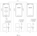
- FIG. 1 c is a schematic diagram of a process of disabling a vibration prompt of an alarm clock
- FIG. 2 a is a schematic diagram 2 of a structure of an electronic device
- FIG. 2 b is a schematic diagram of a level change of an internal signal of the electronic device in FIG. 2 a;
- FIG. 3 a is a schematic diagram of current transmission paths of a drive control apparatus 202 for a brushless motor in a period t 0 :
- FIG. 3 b is a schematic diagram of changes in a first control signal n 1 and a current I of a motor M in a working process of the brushless motor in FIG. 2 a;
- FIG. 3 c ( 1 ) and FIG. 3 c ( 2 ) are a schematic diagram of current transmission paths of a drive control apparatus 202 for a brushless motor in a period t 1 ;
- FIG. 3 d is a schematic diagram of current transmission paths of a drive control apparatus 202 for a brushless motor in a period t 2 ;
- FIG. 3 e is a schematic diagram of a change in vibration strength of a mobile phone
- FIG. 4 a is a schematic diagram 2 of a structure of an electronic device:
- FIG. 4 b is a schematic diagram 3 of a structure of an electronic device
- FIG. 4 c is a schematic diagram 4 of a structure of an electronic device:
- FIG. 4 d is a schematic diagram 5 of a structure of an electronic device
- FIG. 4 e is a schematic diagram 6 of a structure of an electronic device.
- FIG. 4 f is a schematic diagram 7 of a structure of an electronic device.
- words such as “example” or “for example” are used to represent giving examples, illustrations, or descriptions. Any embodiment or design solution described as “example” or “for example” in embodiments of this application should not be construed as being more preferred or advantageous than other embodiments or design solutions. Specifically, the words such as “example” or “for example” are used to present related concepts in a specific manner.
- a brushless motor may also be referred to as a brushless direct current motor.
- the brushless direct current motor includes a motor body and a driver, and is a typical electromechanical product.
- the brushless direct current motor includes a permanent magnet rotor, a multi-pole winding stator, a position sensor, and the like, and is widely used in mobile phones, high-end tape decks, video recorders, electronic instruments, and automatic office equipment.
- a characteristic of an inductor is that a current passing through the inductor cannot abruptly change. When the current in the inductor changes, a self-induced electromotive force is generated at two ends of the inductor, to prevent the change of the current. If there is no current passing through the inductor, when a circuit is connected, the inductor attempts to prevent a current from flowing through the inductor. If there is a current passing through the inductor, when a circuit is disconnected, the inductor attempts to maintain the current unchanged.
- the inductor is an element that can convert electric energy into magnetic energy for storage. Windings, coils, and the like may all be understood as inductors.
- a voltage between a gate and a source that is, a gate-source voltage VGS
- a gate-source voltage VGS of a PMOS transistor is more negative, on resistance of a channel is smaller, and a value of a current is larger.
- the gate-source voltage VGS is less than a turn-on voltage
- the PMOS transistor is conducted.
- the gate-source voltage VGS is greater than or equal to the turn-on voltage, the PMOS transistor is cut off.
- a voltage between a gate and a source that is, a gate-source voltage VGS
- VGS gate-source voltage
- the NMOS transistor is conducted.
- the gate-source voltage VGS is less than or equal to the turn-on voltage, the NMOS transistor is cut off.
- the mobile phone implements a vibration function of the mobile phone by controlling start and stop of a brushless motor.
- a processor in the mobile phone controls, by using a control signal, the brushless motor to be turned on.
- the brushless motor is turned on, rotation of a rotor in the brushless motor generates vibration, so that the mobile phone generates vibration.
- the processor in the mobile phone controls, by using a control signal, the brushless motor to be turned off, the rotor of the brushless motor stops rotating, and the mobile phone stops vibrating.
- FIG. 1 a A schematic diagram of a structure of the mobile phone may be shown in FIG. 1 a .
- the processor is connected to a drive control circuit for the brushless motor, and the processor sends a control signal S 0 to a control end of a PMOS transistor Q 0 , to control conduction and cut-off of Q 0 .
- a branch on which a power supply U, a resistor R 0 , the PMOS transistor Q 0 , and the brushless motor M are located is connected, the power supply U supplies power to the brushless motor M, a current flows through the brushless motor M, and the rotor in the brushless motor M rotates to generate vibration.
- a vibration process of the mobile phone is described with reference to FIG. 1 a and FIG. 1 b .
- the brushless motor M is controlled to be turned on.
- the processor outputs a control signal S 0 in a low-level state.
- Q 0 shown in FIG. 1 a is conducted in the period t 0 .
- a current I inside the brushless motor M gradually increases.
- the control signal SO output by the processor continues to be in the low-level state, the current I inside the brushless motor M is gradually stabilized, and then the brushless motor M stably generates vibration.
- the control signal S 0 is at a high level in a turn-off period 2
- Q 0 shown in FIG. 1 a is cut off in the period t 2
- the power supply U no longer supplies power to the brushless motor M.
- the current I in the brushless motor M does not immediately change to 0 after the power supply U stops supplying power to the brushless motor M.
- the brushless motor M has a winding. It can be learned from the foregoing technical principle description that the winding has a characteristic of preventing a current change. If there is originally a current that passes through, when a circuit is suddenly disconnected, the winding attempts to maintain the current unchanged. Therefore, in the period t 2 , the current in the brushless motor M does not decrease to 0 at once. As shown in a section ab in FIG.
- the current in the brushless motor M first decreases and then increases, and an inductor in the brushless motor M attempts to maintain the original current I unchanged. Therefore, a turn-off response time (that is, the turn-off period t 2 ) of the brushless motor M is relatively long, and the brushless motor M cannot be quickly turned off, that is, vibration of the mobile phone cannot be quickly stopped.
- the following uses a vibration alert scenario of an alarm clock of the mobile phone as an example for description.
- an alarm clock set by a user for 8.00 rings as shown in (1) in FIG. 1 c
- the mobile phone is vibrating, and a mobile phone interface prompts the user to select “Snooze (10 minutes)” or “Slide up to turn off alarm”.
- the control signal S 0 sent by the processor in the mobile phone is at a low level, Q 0 is conducted, a flowing direction of a current in the circuit is shown by a thick solid-line arrow in (1) in FIG.
- the mobile phone does not stop vibrating immediately after the user performs the operation to turn off the alarm clock.
- a turn-off response time of the brushless motor is relatively long, and the brushless motor cannot be quickly turned off. Consequently, power consumption in a process of turning off the motor is relatively high.
- the brushless motor may be actually understood as a component made by using a brushless motor.
- the brushless motor may be applied to components such as a brushless motor, a solenoid valve, and a gradient valve. It is found through research that a drive control solution for components such as a solenoid valve and a gradient valve is similar to the foregoing drive control solution for the brushless motor, turn-on and turn-off are also controlled by using a control signal, and there is also a problem that a turn-off period is too long and running of a motor cannot be quickly stopped.
- this application provides a drive control apparatus for a brushless motor and a related device, to accelerate energy consumption of a brushless motor by using a discharge circuit after a circuit is disconnected, so that running of the brushless motor can be quickly stopped.
- an embodiment of this application discloses an electronic device.
- the electronic device may be a mobile phone, a tablet computer, a desktop computer, a laptop computer, a notebook computer, an ultra-mobile personal computer (Ultra-mobile Personal Computer, UMPC), a handheld computer, a netbook, a personal digital assistant (Personal Digital Assistant, PDA), a wearable electronic device, a smart watch, or the like.
- the electronic device has a brushless motor, and can implement stable working of the brushless motor. Different electronic devices may implement different functions by controlling running of brushless motors, for example, may implement a vibration function, a valve function, and the like.
- the electronic device is a mobile phone and the brushless motor is specifically a brushless motor is used for description below.
- FIG. 2 a is a schematic diagram 1 of a structure of an electronic device according to an embodiment of this application.
- FIG. 2 a includes a processor 210 and a drive control apparatus 202 for a brushless motor.
- the drive control apparatus 202 for the brushless motor includes a discharge circuit 2021 , a motor drive circuit 2022 , a control circuit 2023 , a freewheeling circuit 2024 , and a current monitoring circuit 2025 .
- the processor 201 is mainly configured to execute an instruction according to an execution sequence and an execution time that are specified by a program, and perform arithmetic operation and logical operation on data.
- the processor 201 is configured to output a first control signal n 1 , and the first control signal n 1 is used to control working states such as turn-on, stable running, and turn-off of the brushless motor M.
- n 1 may be a pulse width modulation signal, and the processor may control turn-on, stable running, and turn-off of the brushless motor M by outputting signals n 1 with different duty cycles and different level states.
- the processor 201 is further configured to collect a second monitoring voltage Vout, and calculate a current I of the brushless motor based on a value of the second monitoring voltage Vout.
- the processor 201 may control a working status of the brushless motor M based on the current I of the brushless motor. For example, when a value of the current I of the brushless motor M is excessively large and exceeds a specified threshold, the brushless motor M may be controlled to be turned off to enter a turn-off period, or a duty cycle of the signal n 1 may be reduced, to protect the brushless motor.
- the processor 201 may not collect the second monitoring voltage Vout, that is, the current of the brushless motor M may not be monitored.
- the processor 210 may include one or more processing units.
- the processor 210 may include an application processor (application processor, AP), a modem processor, a graphics processing unit (graphics processing unit, GPU), an image signal processor (image signal processor, ISP), a controller, a video codec, a digital signal processor (digital signal processor, DSP), a baseband processor, and/or a neural-network processing unit (neural-network processing unit, NPU).
- Different processing units may be independent components, or may be integrated into one or more processors.
- a memory may further be disposed in the processor 210 , to store instructions and data.
- the drive control apparatus 202 for the brushless motor includes a discharge circuit 2021 , a motor drive circuit 2022 , a drive signal generation circuit 2023 , a freewheeling circuit 2024 , and a current monitoring circuit 2025 .
- the discharge circuit 2021 is connected to the brushless motor M and the motor drive circuit 2022 , and the motor drive circuit 2022 is connected to the brushless motor M.
- the current monitoring circuit 2025 is connected to the processor 201 and the motor drive circuit 2022 .
- the drive signal generation circuit 2023 is connected to the processor 201 , the discharge circuit 2021 , the motor drive circuit 2022 , and the freewheeling circuit 2024 .
- the discharge circuit 2021 includes a first MOS transistor Q 1 and a first resistor R 1 .
- a first end of the first MOS transistor Q 1 is connected to one end of the first resistor, a second end of the first MOS transistor Q 1 is connected to a first end of the brushless motor M, and a control end of Q 1 receives a first drive signal S 1 .
- the other end of the first resistor R 1 is connected to a second end of the brushless motor M, and a common end between the first resistor R 1 and the brushless motor M is grounded.
- the first drive signal S 1 is used to control conduction/cut-off of the first MOS transistor Q 1 .
- the motor drive circuit 2022 includes a second MOS transistor Q 2 and a second resistor R 2 .
- a first end of the second MOS transistor Q 2 is connected to one end of the second resistor R 2
- a second end of the second MOS transistor is connected to the first end of the brushless motor M.
- a control end of the second MOS transistor Q 2 receives a second drive signal S 2 .
- the second end of the brushless motor M is grounded.
- the other end of the second resistor R 2 receives a supply voltage U.
- the second drive signal S 2 is used to control conduction/cut-off of the second MOS transistor Q 2 .
- the drive signal generation circuit 2023 includes a third resistor R 3 , a fourth resistor R 4 , a fifth resistor R 5 , a sixth resistor R 6 , a fourth MOS transistor Q 4 , a fifth MOS transistor Q 5 , a sixth MOS transistor Q 6 , a phase inverter A 1 , and a first capacitor C 1 .
- One end of the third resistor R 3 receives the supply voltage U, the other end of the third resistor R 3 is connected to a second end of the fourth MOS transistor Q 4 , and a first end of the fourth MOS transistor Q 4 is grounded.
- a control end of the fourth MOS transistor Q 4 receives a second control signal n 2 .
- One end of the fifth resistor R 5 receives the supply voltage U, the other end of the fifth resistor R 5 is connected to a second end of the fifth MOS transistor Q 5 , and a first end of the fifth MOS transistor Q 5 is grounded.
- a control end of the fifth MOS transistor Q 5 receives the first control signal n 1 .
- One end of the fourth resistor R 4 receives the first control signal n 1 , the other end of the fourth resistor R 4 is connected to one end of the first capacitor C 1 , and the other end of the first capacitor C 1 is grounded.
- a common end between the fourth resistor R 4 and the first capacitor C 1 outputs a third control signal n 3 .
- An input end of the phase inverter A 1 receives the third control signal n 3 , and an output end of the phase inverter A 1 outputs the second control signal n 2 .
- One end of the sixth resistor R 6 receives the supply voltage, the other end of the sixth resistor R 6 is connected to a second end of the sixth MOS transistor Q 6 , and a first end of the sixth MOS transistor Q 6 is grounded.
- a common end between the third resistor and the fourth switching transistor outputs the first drive signal S 1 .
- a common end between the sixth resistor R 6 and the sixth MOS transistor Q 6 outputs a third drive signal S 3
- a common end between the fifth MOS transistor Q 5 and the fifth resistor R 5 outputs the second drive signal S 2 .
- the first control signal n 1 is used to control conduction/cut-off of the fifth MOS transistor Q 5
- the second control signal n 2 is used to control conduction/cut-off of the fourth MOS transistor Q 4
- the third control signal n 3 is used to control conduction/cut-off of the sixth MOS transistor Q 6 .
- the freewheeling circuit 2024 includes a third MOS transistor Q 3 and a diode D 1 .
- a first end of the third MOS transistor Q 3 is connected to a cathode of the diode, and a second end of the third MOS transistor Q 3 is connected to the first end of the brushless motor M.
- a control end of the third MOS transistor Q 3 receives the third drive signal S 3 .
- An anode of the diode D 1 is connected to the second end of the brushless motor M, and a common end between the diode D 1 and the brushless motor M is grounded.
- the third drive signal S 3 is used to control conduction/cut-off of the third MOS transistor Q 3 .
- the current monitoring circuit 2025 includes a seventh resistor R 7 , an eighth resistor R 8 , a ninth resistor R 9 , a tenth resistor R 10 , and an operational amplifier A 2 .
- One end of the seventh resistor R 7 receives a first voltage V 1
- the other end of the seventh resistor R 7 is connected to an in-phase input end of the operational amplifier A 2
- one end of the eighth resistor R 8 is connected to the in-phase input end of the operational amplifier A 2
- the other end of the eighth resistor R 8 is connected to a positive power end of the operational amplifier A 2 .
- One end of the ninth resistor R 9 receives a second voltage V 2 , and the other end of the ninth resistor R 9 is connected to an inverting input end of the operational amplifier A 2 .
- One end of the tenth resistor R 10 is connected to the inverting input end of the operational amplifier A 2 , and the other end of the tenth resistor R 10 is grounded.
- a negative power end of the operational amplifier A 2 is grounded.
- An output end of the operational amplifier A 2 outputs the second monitoring voltage Vout.
- a difference between the first voltage V 1 and the second voltage V 2 that is, a voltage V 1 -V 2 between the seventh resistor R 7 and the ninth resistor R 9 , is referred to as a first monitoring voltage.
- the operational amplifier A 2 is configured to amplify a value of the first monitoring voltage by a multiple of
- the first voltage V 1 is the supply voltage U. In some other embodiments, the first voltage V 1 may not be equal to the supply voltage U.
- a magnification of the operational amplifier A 2 may be adjusted by adjusting values of R 7 and R 8 .
- the second monitoring voltage is
- Vout R ⁇ 8 R ⁇ 7 ⁇ ( V ⁇ 1 - V ⁇ 2 ) .
- the current of the brushless motor is
- the processor 201 collects the value of Vout, and may calculate the monitored current I by using values of Vout, R 7 , R 8 , and R 2 . In some other embodiments, if the processor 201 does not need to monitor the current I of the brushless motor M, the drive control apparatus 202 for the brushless motor may have no current monitoring circuit 2025 .
- Q 1 , Q 2 , and Q 3 are PMOS transistors
- Q 4 , Q 5 , and Q 6 are NMOS transistors.
- a first end of an MOS transistor mentioned in FIG. 2 a may refer to a source of the MOS transistor
- a second end of the MOS transistor may refer to a drain of the MOS transistor
- a control end of the MOS transistor refers to a gate of the MOS transistor.
- the MOS transistor in this embodiment of this application mainly functions as a switch. Therefore, in some other embodiments, the MOS transistor in FIG. 2 a may alternatively be a switching transistor whose conduction/cut-off can be controlled, for example, a relay or a transistor.
- control apparatus 202 for the brushless motor may be integrated into one or more chips and placed in the electronic device.
- the discharge circuit 2021 , the motor drive circuit 2022 , the drive signal generation circuit 2023 , the freewheeling circuit 2024 , and the current monitoring circuit 2025 may be separately integrated into chips.
- the first control signal n 1 output by the processor 201 may be shown in FIG. 2 b .
- the first control signal n 1 output by the processor 201 is at a high level, and the processor 201 outputs the first control signal n 1 in a high-level state to the control apparatus 202 for the brushless motor, to control the brushless motor M to be turned on.
- a trigger manner in which the processor 201 generates the first control signal in the period t 0 may be triggering by ringing of an alarm clock, triggering by a special effect in a game process of a user, or the like.
- This embodiment of this application sets no limitation on a manner of triggering generation of the first control signal n 1 in the period t 0 , provided that the processor 201 generates, in the period t 0 , the first control signal n 1 that can be used to turn on the brushless motor M.
- Duration of the period t 0 may be set by the processor. In some embodiments, duration required for completely turning on the brushless motor M may be determined through experiment, and then the duration is set to duration of t 0 .
- a manner of setting a value of t 0 is not limited in this embodiment of this application.
- the first control signal n 1 and the third control signal n 3 in the electronic device shown in FIG. 2 a are in a high-level state, and the second control signal n 2 is in a low-level state.
- the first drive signal S 1 is in a high-level state, and the second drive signal S 2 and the third drive signal S 3 are in a low-level state.
- the control end of the fifth MOS transistor Q 5 receives the first control signal n 1 at the high level, and Q 5 is in a conducted state. As shown by a path A in FIG. 3 a , after Q 5 is conducted, a current flows from a power supply to the ground through R 5 and Q 5 . Therefore, the second drive signal S 2 output by the common end between R 5 and Q 5 is at a low level.
- the first control signal n 1 undergoes filtering and rectification processing performed by R 4 and C 1 , and the third control signal n 3 in a high-level state is generated at the common end between R 4 and C.
- the control end of the sixth MOS transistor Q 6 receives the third control signal n 3 , and Q 6 is in a conducted state under control of n 3 at a high level Therefore, as shown by a path B in FIG. 3 a , a current flows from the power supply U to the ground through R 6 and Q 6 . Therefore, the third drive signal S 3 output by the common end between R 6 and Q 6 is at a low level.
- the third control signal n 3 is input to the phase inverter A 1 , and the phase inverter A 1 obtains and outputs the second control signal n 2 that is inverted to the third control signal n 3 . Because the third control signal n 3 is in a high-level state, the second control signal n 2 is in a low-level state.
- the control end of the fourth MOS transistor Q 4 receives the second control signal n 2 , and Q 4 is in a cut-off state under control of the second control signal n 2 in the low-level state. Therefore, as shown by a path C in FIG. 3 a , a current is output from the power supply U, and does not flow through Q 3 after passing through R 3 , but is directly output to the discharge circuit 2021 . Therefore, the first drive signal S 1 output by the common end between R 3 and Q 3 is in a high-level state.
- I is the current in the brushless motor M.
- the value of the first monitoring voltage is proportional to the current in the brushless motor M, the first monitoring voltage can reflect the current in the brushless motor M within t 0 .
- R 2 and M divide the supply voltage U. Therefore, in this case, a voltage Um between two ends of the brushless motor M may be considered to be equal to U ⁇ (V 1 ⁇ V 2 ).
- a value of the current I in the brushless motor M gradually increases. Because there is a winding in the brushless motor M, due to impact of a characteristic of an inductor, the brushless motor M prevents a current change. Therefore, in the period t 0 , the current in the brushless motor M decreases and then continues to increase.
- the voltage Um provided by the supply voltage U for the brushless motor M in the period t 0 may be increased by increasing a value of the supply voltage U or by reducing a value of R 2 to reduce a voltage obtained by R 2 from the supply voltage U, so that a value of Um is greater than or equal to a turn-on voltage of the brushless motor M.
- an overvoltage turn-on voltage is provided for the brushless motor M, so that the brushless motor M is turned on in an overvoltage manner.
- duration t 0 for completing turn-on of the brushless motor M decreases. Overvoltage refers to exceeding a stable working voltage of the brushless motor M.
- duration of the turn-on period t 0 is relatively short, even if the brushless motor M is in the overvoltage turn-on state in a short time period, the motor is not affected, and a time required for turning on the brushless motor M can be reduced.
- the first drive signal S 1 output by the drive signal generation circuit in the period t 0 is at a high level.
- the first MOS transistor Q 1 is in a cut-off state under control of S 1 in a high-level state. Therefore, no current flows through a branch in which Q 1 and R 1 are located.
- the entire discharge circuit is not in a working state in the period t 0 .
- the motor drive circuit 2022 outputs the first monitoring voltage to the current monitoring circuit 2025 in the period t 0 . It can be learned from the foregoing description of the current monitoring circuit 2025 in FIG. 2 a that the current monitoring circuit 2025 may amplify the first monitoring voltage to obtain and output the second monitoring voltage Vout, and the value of Vout can be used to calculate the current I in the brushless motor.
- the current monitoring circuit 2025 may output the second monitoring voltage Vout to the processor 201 , so that the processor monitors the current I in the brushless motor in the period t 0 .
- the processor 201 outputs the first control signal n 1 to the drive signal generation circuit 2023 , so that the drive signal generation circuit 2023 obtains and outputs the first drive signal S 1 , the second drive signal S 2 , and the third drive signal S 3 . Then, after receiving the second drive signal S 2 , the motor drive circuit 2022 turns on the brushless motor M and outputs the first monitoring voltage.
- the freewheeling circuit 2024 does not work under control of the third drive signal S 3
- the discharge circuit 2021 does not work under control of the first drive signal S 1 .
- the current monitoring circuit 2025 amplifies the received first monitoring voltage to obtain and output the second monitoring voltage Vout.
- the second monitoring voltage Vout is output to the processor 201 .
- the processor 201 obtains the current I in the brushless motor M by using the second monitoring voltage Vout, to monitor the current I in the brushless motor M in the period t 0 .
- the first control signal n 1 output by the processor 201 may be shown in FIG. 2 b .
- the first control signal n 1 output by the processor 201 may be a pulse width modulation (Pulse width modulation, PWM) signal whose duty cycle is k.
- PWM pulse width modulation
- the processor 201 outputs the first control signal n 1 in a PWM form to the control apparatus 202 for the brushless motor, to control the brushless motor M to work stably.
- a type of the first control signal n 1 generated by the processor 201 in the period t 11 is preset by using a program. For example, it is specified that a first control signal n 1 whose duty cycle is 50% and that is in a PWM form is output in the period t 1 .
- This embodiment of this application sets no limitation on a manner in which the processor 201 triggers to enter the period t 1 and a manner in which the processor 201 triggers to end the period t 1 .
- the processor 201 automatically triggers to enter the period t 1 after the period t 0 ends, and outputs a first control signal n 1 that matches the period t 1 , and then the processor 201 ends the period t 1 after receiving an operation instruction triggered by the user.
- the processor ends the period t 1 , starts control in the period t 2 , and outputs a first control signal n 1 that matches the period t 2 .
- the first control signal n 1 output by the processor 201 in the period t 1 may be different from that in FIG. 2 b .
- a first control signal n 1 in a high-level state may be output in the period t 1 .
- the first control signal n 1 output by the processor 201 in the period t 1 may have many specific level states. This is not limited in this embodiment of this application, provided that the first control signal n 1 output by the processor 201 in the period t 1 can control the brushless motor M in the control apparatus 202 for the brushless motor to enter a stable working state.
- the first control signal n 1 in the electronic device shown in FIG. 2 a is a PWM signal
- the second control signal n 2 is a low-level signal
- the third control signal n 3 is a high-level signal
- the first drive signal S 1 is a high-level signal
- the second drive signal S 2 is a PWM signal inverted to the first control signal n 1
- the third drive signal S 3 is a low-level signal.
- the control end of the fifth MOS transistor Q 5 receives the first control signal n 1 in a PWM form, and Q 5 is in a conducted state in a high-level period of the first control signal n 1 .
- a path E in FIG. 3 c ( 1 ) when n 1 is in a high-level state, Q 5 is conducted, and a current is output from the power supply and flows through R 5 and Q 5 to the ground. Therefore, the second drive signal S 2 output by the common end between R 5 and Q 5 is at a low level.
- the output second drive signal S 2 is at a high level, and a transmission path of a branch in which Q 5 is located is shown as the path F in FIG. 3 c ( 2 ). Therefore, the second drive signal S 2 output by the drive signal generation circuit 2023 in the period t 1 is equivalent to a PWM signal inverted to n 1 .
- the first control signal n 1 undergoes filtering and rectification processing performed by R 4 and C 1 , and the third control signal n 3 that is always in a high-level state is generated at the common end between R 4 and C 1 .
- the obtained third control signal n 3 is at a high level.
- a path G in FIG. 3 c ( 1 ) in the period t 1 , when n 1 is at a high level, n 3 is also at a high level.
- the third drive signal S 3 output by the common end between R 6 and Q 6 is a low-level signal.
- FIG. 3 c ( 2 ) in the period t 1 , when n 1 is at a low level, n 3 is still at a high level. Therefore, a transmission path of a branch in which Q 6 is located is still the path G, and the output third drive signal S 3 is still a low-level signal.
- the signal n 1 is a PWM wave. Therefore, after rectification by R 4 and C 1 , a voltage value of the obtained third control signal n 3 that is always in a high-level state is less than that of n 1 . Further, a voltage value of a high level received by the control end of Q 6 is small, voltage stress in the control apparatus 202 for the brushless motor is lower, and a life is longer.
- the third control signal n 3 is input to the phase inverter A 1 , and the phase inverter A 1 obtains and outputs the second control signal n 2 inverted to n 3 . Because n 3 is at a high level in the period t 1 , n 2 is at a low level.
- the control end of Q 4 receives the signal n 2 , and Q 4 is in a cut-off state under control of n 2 at a low level. Therefore, in a path H shown m FIG.
- the second drive signal S 2 is at a high level. Therefore, as shown in FIG. 3 c ( 2 ).
- Q 2 is in a cut-off state under control of S 2 at the high level, a branch in which the brushless motor M is located has no power supply, and the two ends of R 2 no longer output the first monitoring voltage to the current monitoring circuit 2025 .
- the branch in which the brushless motor M is located should be disconnected, and no current flows through.
- the brushless motor M has an inductor characteristic, maintains an original current, and prevents a change in the current. Therefore, as shown in a path J, the brushless motor M generates an induced current to maintain an original current direction, and the brushless motor M can still work normally.
- a control signal S 0 is in a low-level state in both a turn-on period and a stable working period.
- the brushless motor M in FIG. 1 a is powered by the supply voltage U in both the turn-on period and the stable working period. Therefore, a value of the supply voltage U cannot be excessively large. Otherwise, the brushless motor M is in an overvoltage state in both the turn-on period and the stable working period, which easily causes damage to the brushless motor M.
- the brushless motor M may be turned on in an overvoltage manner in the period t 0 , and the brushless motor M may be intermittently powered by the power supply in the period t 1 under control of the signal n 1 with a preset duty cycle, instead of being always powered by the power supply. This reduces power consumption of the brushless motor M, and saves energy.
- the first drive signal S 1 output by the drive signal generation circuit in the period t 1 is always at a high level.
- the first MOS transistor Q 1 is in a cut-off state under control of S 1 in a high-level state. Therefore, no current flows through a branch in which Q 1 and R 1 are located.
- the entire discharge circuit is not in a working state in the period t 0 .
- the brushless motor M maintains an original current direction.
- an induced electromotive force generated by the brushless motor M due to an inductor characteristic is equivalent to a positive voltage applied to D 1 , and D 1 is conducted.
- Q 3 is also conducted, the current flows through D 1 and Q 3 from the brushless motor M, and then returns to the brushless motor M to form a path K, that is, the brushless motor M, D 1 , and Q 3 form a loop.
- D 1 performs freewheeling for the brushless motor M, so that the induced current generated by the brushless motor M is consumed in the loop in a freewheeling manner. This protects another component in the circuit from being damaged by the electromotive force generated by the brushless motor M.
- the brushless motor M can continue to work normally until energy is used up.
- n 1 changes to a high-level signal, the brushless motor M continues to work with power supply.
- the duty cycle of n 1 may be set based on the turn-off response time of the brushless motor M.
- the turn-off response time of the brushless motor M refers to duration from a moment at which Q 2 is cut off and the power supply no longer supplies power to the brushless motor M to a moment at which the brushless motor M stops running.
- low-level duration of n 1 may be set to be less than the turn-off response time. Further, in the period t 1 , the brushless motor M can always maintain a running state.
- the first control signal n 1 may alternatively be a signal that is always in a high-level state in the period t 1 .
- n I When n I is always in the high-level state, a current path formed in the control apparatus 202 for the brushless motor is always that shown in FIG. 3 c ( 1 ).
- FIG. 3 c ( 1 ) For details, refer to the description in FIG. 3 c ( 1 ). Details are not described herein again.
- n 1 is a low-level signal
- the motor drive circuit 2022 does not output the first monitoring voltage
- the current monitoring circuit 2025 does not work
- the second monitoring voltage Vout is 0.
- the first control signal n 2 output by the processor 201 may be shown in FIG. 2 b , and is a low-level signal. Triggering the processor 201 to generate, in the period t 2 , the signal n 1 that matches the period t 2 may be preset by using the processor 201 . For example, it is specified that after a turn-off operation instruction of the user is detected, the period t 2 is entered, and the signal n 1 that matches the period t 2 is triggered to be generated. However, there are many manners for triggering the processor 201 to enter the period t 2 and generate the signal n 1 that matches the period t 2 . This is not limited in this embodiment of this application.
- the first control signal n 1 output by the processor 201 in the period t 2 may be different from that in FIG. 2 b .
- a first control signal n 1 in a high-level state may be output in the period 2 .
- the first control signal n 1 output by the processor 201 in the period t 1 may have many specific level states. This is not limited in this embodiment of this application, provided that the first control signal n 1 output by the processor 201 in the period t 2 can control the brushless motor M in the control apparatus 202 for the brushless motor to enter a turn-off state.
- the first control signal n 1 in the electronic device shown in FIG. 2 a is a low-level signal
- the second control signal n 2 is a high-level signal
- the third control signal n 3 is a low-level signal
- the first drive signal S 1 is a low-level signal
- the second drive signal S 2 is a high-level signal
- the third drive signal S 3 is a high-level signal.
- the control end of Q 5 receives the signal n 1 in the low-level state, and Q 5 is in a cut-off state under control of n 1 at the low level.
- a path L in FIG. 3 d when n 1 is in a low-level state, Q 5 is cut off, and after being output from the power supply, a current does not pass through Q 5 , but is directly output to the motor drive circuit 2022 through R 5 , that is, a second drive signal S 2 in a high-level state is output.
- a third control signal n 3 output by the common end between R 4 and C 1 is a low-level signal, and Q 6 is in a cut-off state under control of n 3 at the low level.
- Q 6 is cut off, and after being output from the power supply, a current does not pass through Q 6 , but is directly output to the freewheeling circuit 2024 through R 6 , that is, a third drive signal S 3 in a high-level state is output.
- n 3 is input to the phase inverter A 1 , a signal n 2 that is inverted to n 3 is obtained. Because n 3 is at a low level, n 2 is at a high level. Q 4 is conducted under control of n 2 at the high level. As shown by a path N in FIG. 3 d , a current is output from the power supply and flows to the ground through R 3 and Q 4 . Therefore, the first drive signal S 1 output by the common end between R 3 and Q 4 is at a low level.
- the brushless motor M maintains an original current direction, generates an induced current, and outputs the generated induced current to the discharge circuit 2021 .
- the brushless motor M does not stop running immediately.
- the brushless motor M does not stop running until energy in the brushless motor M is completely consumed.
- the current in the brushless motor M does not directly change to 0, and due to impact of the inductor characteristic, the current in the brushless motor M transitorily increases in a section cd.
- the brushless motor M does not stop running and the current does not change to 0 until the energy in the brushless motor M is completely consumed.
- the first MOS transistor Q 1 is in a conducted state under control of S 1 in a low-level state, and a current output by the brushless motor M may flow through a branch in which Q 1 and R I are located, to form a path P.
- the current passes through R 1 , power consumption is generated on R 1 , and energy consumption in the brushless motor M is accelerated, that is, the brushless motor M is discharged, so that the brushless motor M can quickly stop running.
- an equivalent inductance value of the brushless motor M is L
- R 1 is equivalent to a discharge resistor.
- the induced current in the brushless motor applies work through R 1 , and R 1 converts electric energy into internal energy, to quickly consume the electric energy of the brushless motor.
- another discharge component may be used to implement a discharge function, such as a bulb or a thermistor.
- the discharge component includes but is not limited to the content provided in embodiments of this application.
- the discharge circuit 2021 discharges the brushless motor M in the turn-off period t 2 , to quickly stop the brushless motor. In this way, the brushless motor can stop running in a short period t 2 .
- duration of the period t 2 is shorter, so that the brushless motor M is applicable to more working frequencies, and modes at various working frequencies are applicable.
- the brushless motor M in this embodiment of this application may work on a vibration band in t 11 or a vibration band in t 12 .
- turn-on duration and turn-off duration of the brushless motor M are relatively short, and the brushless motor M can be quickly turned on and turned off.
- the vibration bands t 11 and t 12 in this embodiment of this application are shorter, so that a time interval t 13 between the vibration bands can be shorter, and can be applicable to a scenario at a relatively high working frequency.
- the brushless motor in the mobile phone is quickly turned off, and this is applicable to a scenario in which the brushless motor in the mobile phone works at a vibration frequency of 100-150 Hz. Strong vibration at a low frequency can improve human ear comfort.
- a circuit structure of the drive signal generation circuit 2023 may have many types. In different circuit structures, specific processes of generating the first drive signal S 1 , the second drive signal S 2 , and the third drive signal S 3 by using the first control signal n 1 in different periods may be different. This is not limited in this embodiment of this application. In some other embodiments, all drive signals and control signals in this embodiment of this application may alternatively be generated by the processor 201 , that is, the drive signal generation circuit 2023 may alternatively be a software logic circuit, and may be disposed in the processor 201 .
- An actual function of the freewheeling circuit 2024 is to perform freewheeling on the brushless motor M in the stable working period t 1 , to maintain running of the brushless motor M and protect components in the circuit.
- a circuit structure of the freewheeling circuit 2024 may have many types, including but not limited to the content provided in this application.
- a function of the current monitoring circuit 2025 is to output the second monitoring voltage that can be used to reflect a current value of the brushless motor M to the processor 201 , so that the processor 201 monitors the current value of the brushless motor M by receiving the second monitoring voltage.
- a circuit structure of the current monitoring circuit 2025 may have many types, including but not limited to the content provided in this application.
- an actual function of the discharge circuit 2021 is to control to discharge the brushless motor M in the turn-off period t 2 , to accelerate energy consumption of the brushless motor M.
- the drive signal generation circuit 2023 controls the discharge circuit 2021 to work in the period t 2 .
- the discharge circuit 2021 generates power consumption by receiving the induced current in the brushless motor M, to consume energy of the brushless motor M, reduce duration required for turning off the brushless motor M, and quickly turn off the brushless motor M.
- a circuit structure of the discharge circuit 2021 may have many types, including but not limited to the content provided in this application.
- the motor drive circuit 2022 continuously provides an overvoltage turn-on voltage for the brushless motor M under control of the second drive signal, so that the brushless motor M is turned on in an overvoltage manner, thereby shortening duration to required for turning on the brushless motor M, and achieving a quick turn-on effect
- the motor drive circuit 2022 supplies power to the brushless motor under control of the second drive signal; or when the second drive signal is in a second level state, for example, a high-level state, power supply to the brushless motor is stopped, and the induced current generated by the brushless motor is output to the freewheeling circuit 2024 . Further, the freewheeling circuit 2024 may perform freewheeling on the induced current from the brushless motor under control of the third drive signal, so that the brushless motor M works stably and continuously.
- the motor drive circuit 2022 intermittently supplies power to the brushless motor, instead of continuously supplying power to the brushless motor, and the freewheeling circuit 2024 performs freewheeling for the brushless motor.
- the brushless motor M intermittently supplies power to the brushless motor, even if the motor drive circuit 2022 provides an overvoltage turn-on voltage for the brushless motor M, the brushless motor M is not in an overvoltage turn-on state for a long time, and is not damaged due to long-term overvoltage turn-on.
- the motor drive circuit 2022 stops supplying power to the brushless motor, and outputs the induced current generated by the brushless motor to the discharge circuit 2021 .
- the discharge circuit 2021 receives the induced current, and applies work by using the induced current, to consume electric energy of the brushless motor. This accelerates energy consumption of the brushless motor M, so that duration t 2 required for turning off the brushless motor M is short, and a quick turn-off effect is achieved.
- the current monitoring circuit 2025 receives the first monitoring voltage output by the motor drive circuit 2022 , and amplifies the first monitoring voltage, to obtain and output the second monitoring voltage.
- the first monitoring voltage is used to reflect the current value of the brushless motor. Therefore, the second monitoring voltage obtained after amplification can also reflect the current value of the brushless motor.
- Current monitoring for the brushless motor can be implemented by obtaining a value of the second monitoring voltage. Therefore, when the current of the brushless motor is excessively large, the brushless motor can be controlled to be turned off, to prevent the brushless motor from being damaged due to the excessively large current.
- the electronic device may be shown in FIG. 4 a , and the electronic device includes the processor 201 and the drive control apparatus 202 for the brushless motor.
- the drive control apparatus 202 for the brushless motor includes the motor drive circuit 2022 and the discharge circuit 2021 .
- the processor 201 may output a second drive signal S 2 that is continuously in a low-level state and S 1 that is continuously in a high-level state.
- the motor drive circuit 2022 is controlled by S 2 , a branch in which the supply voltage U, R 2 , Q 2 , and M are located is always in a connected state, and the motor drive circuit 2022 continuously supplies power to the brushless motor M.
- S 1 is in the high-level state. Therefore, in the period t 1 , Q 1 is cut off, a branch in which Q 1 and R 1 are located is not conducted, and the discharge circuit 2021 does not work in the periods t 0 and t 1 .
- the processor 201 outputs a second drive signal S 2 that is continuously in a high-level state and S 1 that is in a low-level state.
- the motor drive circuit 2022 is controlled by S 2 , and Q 2 is cut off.
- the motor drive circuit 2022 stops supplying power to the brushless motor M, and outputs the induced current generated by the brushless motor to the discharge circuit 2021 .
- the discharge circuit 2021 is controlled by S 1 , Q 1 is in a conducted state, and the induced current in the brushless motor flows through Q 1 and R I to apply work, to consume electric energy of the brushless motor and shorten a time required for turning off the brushless motor M.
- the drive control apparatus 202 for the brushless motor may further include the drive signal generation circuit 2023 .
- the second drive signal S 2 and the first drive signal S 1 may be generated by using the drive signal generation circuit 2023 .
- the drive signal generation circuit 2023 generates S 2 and S 1 based on the signal n 1 output by the processor 201 .
- FIG. 3 a For a process in which the drive signal generation circuit 2023 generates S 2 and S 1 based on the signal n 1 output by the processor 201 , refer to the related descriptions of the drive signal generation circuit 2023 in FIG. 3 a , FIG. 3 c ( 1 ) and FIG. 3 c ( 2 ), and FIG. 3 d . Details are not described herein again.
- the electronic device When the brushless motor M wants to implement quick turn-on (that is, shorten the turn-on period t 0 ) and reduce power consumption, the electronic device may be shown in FIG. 4 c , and the electronic device includes the processor 201 and the drive control apparatus 202 for the brushless motor.
- the drive control apparatus 202 for the brushless motor includes the motor drive circuit 2022 and the freewheeling circuit 2024 .
- the processor 201 may output a second drive signal S 2 in a low-level state and a third drive signal S 3 in a low-level state.
- the motor drive circuit 2022 provides an overvoltage turn-on voltage for the brushless motor M under control of the second drive signal S 2 , so that the brushless motor M is turned on in an overvoltage manner, to quickly turn on the brushless motor.
- Q 3 in the freewheeling circuit 2024 is conducted under control of S 3 .
- the freewheeling circuit 2024 does not work under control of S 3 in the period t 0 .
- the processor 201 may output S 2 that is a PWM wave and a third drive signal S 3 that is in a low-level state.
- S 2 is at a low level
- the motor drive circuit 2022 supplies power to the brushless motor M.
- S 2 is at a high level
- power supply to the brushless motor M is stopped, and the induced current generated by the brushless motor M is output to the freewheeling circuit 2024 .
- Q 3 in the freewheeling circuit 2024 is conducted under control of S 3 , the induced current flows through D 1 , and D 1 performs freewheeling for the brushless motor M, so that stable working of the brushless motor M is maintained, and power consumption is reduced.
- the motor drive circuit 2022 does not continuously supply power to the brushless motor M, the brushless motor M is not always in an overvoltage turn-on state.
- the processor 201 outputs S 2 in a high-level state and S 3 in a high-level state.
- the motor drive circuit 2022 stops supplying power to the brushless motor M under control of S 2 , and the brushless motor M is completely turned off after stored energy is used up.
- the freewheeling circuit 2024 does not work under control of S 3 .
- the drive control apparatus 202 for the brushless motor may further include the drive signal generation circuit 2023 .
- the second drive signal S 2 and the third drive signal S 3 may be generated by using the drive signal generation circuit 2023 .
- the drive signal generation circuit 2023 generates S 2 and S 3 based on the signal n 1 output by the processor 201 .
- FIG. 3 a For a process in which the drive signal generation circuit 2023 generates S 2 and S 3 based on the signal n 1 output by the processor 201 , refer to the related descriptions of the drive signal generation circuit 2023 in FIG. 3 a , FIG. 3 c ( 1 ) and FIG. 3 c ( 2 ), and FIG. 3 d . Details are not described herein again.
- the electronic device may be shown in FIG. 4 e , and the electronic device includes the processor 201 and the drive control apparatus 202 for the brushless motor.
- the drive control apparatus 202 for the brushless motor includes the motor drive circuit 2022 and the current monitoring circuit 2025 .
- the processor 201 may output a second drive signal S 2 that is continuously in a low-level state.
- the motor drive circuit 2022 is controlled by S 2 , a branch in which the supply voltage U. R 2 , Q 2 , and M are located is always in a connected state, and the motor drive circuit 2022 continuously supplies power to the brushless motor M.
- the processor 201 outputs a second drive signal S 2 that is continuously in a high-level state.
- the motor drive circuit 2022 is controlled by S 2 , Q 2 is cut off, and the motor drive circuit 2022 stops supplying power to the brushless motor M.
- the current monitoring circuit 2025 receives the first monitoring voltage (that is, a difference voltage between a first voltage V 1 and a second voltage V 2 ) output by the motor drive circuit 2022 , and amplifies the first monitoring voltage, to obtain and output the second monitoring voltage Vout.
- the first monitoring voltage is used to reflect the current value of the brushless motor. Therefore, Vout can also reflect the current value of the brushless motor.
- the processor 201 may obtain Vout, and monitor the current of the brushless motor M based on Vout. Therefore, when the current value of the brushless motor M is excessively large, the brushless motor M can be turned off, to protect the brushless motor from being damaged by the excessively large current.
- the drive control apparatus 202 for the brushless motor may further include the drive signal generation circuit 2023 .
- the second drive signal S 2 may be generated by using the drive signal generation circuit 2023 .
- the drive signal generation circuit 2023 generates S 2 based on the signal n 1 output by the processor 201 .
- FIG. 3 a For a process in which the drive signal generation circuit 2023 generates S 2 based on the signal n 1 output by the processor 201 , refer to the related descriptions of the drive signal generation circuit 2023 in FIG. 3 a , FIG. 3 c ( 1 ) and FIG. 3 c ( 2 ), and FIG. 3 d . Details are not described herein again.
- the drive control apparatus 202 for the brushless motor wants to implement a plurality of effects (for example, wants to quickly turn on and turn off the brushless motor)
- the foregoing circuits for implementing related effects may be combined and connected.
- FIG. 2 a , FIG. 3 a , FIG. 3 c ( 1 ) and FIG. 3 c ( 2 ), and FIG. 3 d Details are not described herein again.
Landscapes
- Engineering & Computer Science (AREA)
- Power Engineering (AREA)
- Control Of Motors That Do Not Use Commutators (AREA)
Abstract
Description
to obtain and output the amplified second monitoring voltage Vout. In the embodiment shown in
In this embodiment of this application, the current of the brushless motor is
Therefore, the current of the brushless motor is
In this embodiment of this application, the
Claims (20)
Applications Claiming Priority (3)
| Application Number | Priority Date | Filing Date | Title |
|---|---|---|---|
| CN202111081378.5A CN113938059B (en) | 2021-09-15 | 2021-09-15 | Drive control device of brushless motor and related equipment |
| CN202111081378.5 | 2021-09-15 | ||
| PCT/CN2022/115422 WO2023040639A1 (en) | 2021-09-15 | 2022-08-29 | Drive control device for brushless motor and related device |
Publications (2)
| Publication Number | Publication Date |
|---|---|
| US20240154553A1 US20240154553A1 (en) | 2024-05-09 |
| US12206353B2 true US12206353B2 (en) | 2025-01-21 |
Family
ID=79275656
Family Applications (1)
| Application Number | Title | Priority Date | Filing Date |
|---|---|---|---|
| US18/041,765 Active US12206353B2 (en) | 2021-09-15 | 2022-08-29 | Drive control apparatus for brushless motor and related device |
Country Status (4)
| Country | Link |
|---|---|
| US (1) | US12206353B2 (en) |
| EP (1) | EP4187773B1 (en) |
| CN (1) | CN113938059B (en) |
| WO (1) | WO2023040639A1 (en) |
Families Citing this family (1)
| Publication number | Priority date | Publication date | Assignee | Title |
|---|---|---|---|---|
| CN113938059B (en) * | 2021-09-15 | 2022-11-15 | 荣耀终端有限公司 | Drive control device of brushless motor and related equipment |
Citations (17)
| Publication number | Priority date | Publication date | Assignee | Title |
|---|---|---|---|---|
| US5291106A (en) * | 1992-11-23 | 1994-03-01 | General Motors Corporation | Single current regulator for controlled motoring and braking of a DC-fed electric motor |
| US7170245B2 (en) * | 2003-05-16 | 2007-01-30 | Samsung Electronics Co., Ltd. | Motor power supply control apparatus |
| JP2008018131A (en) | 2006-07-14 | 2008-01-31 | Matsushita Electric Ind Co Ltd | Electric washing machine |
| CN101694979B (en) | 2009-10-20 | 2011-11-02 | 北京航空航天大学 | Electromagnetic torque pulsation suppression device of magnetic suspension reaction fly-wheel motor |
| CN103121409A (en) | 2011-11-18 | 2013-05-29 | 北汽福田汽车股份有限公司 | Automobile braking circuit protecting device and automobile braking device provided with the same |
| CN203788145U (en) | 2014-03-27 | 2014-08-20 | 南京西普尔科技实业有限公司 | Super-capacitor adjustable power controller |
| US8823298B2 (en) * | 2012-03-14 | 2014-09-02 | Whirlpool Corporation | Apparatus and method of braking applied in a laundry treating appliance |
| US9178448B2 (en) * | 2013-01-18 | 2015-11-03 | Fuji Electric Co., Ltd. | Power conversion device |
| CN107107327A (en) | 2014-12-18 | 2017-08-29 | 日立工机株式会社 | Electric tool |
| CN107800336A (en) | 2016-09-01 | 2018-03-13 | 德昌电机(深圳)有限公司 | Motor and its drive circuit, application apparatus and motor braking method |
| US20180175759A1 (en) | 2016-12-16 | 2018-06-21 | Seiko Instruments Inc. | Control device for vibration generation device, electronic apparatus, and method of controlling vibration generation |
| CN109417355A (en) | 2016-06-15 | 2019-03-01 | 三菱电机株式会社 | Motor drive |
| CN111030519A (en) | 2019-12-20 | 2020-04-17 | 江苏科技大学 | Brushless direct current motor rapid braking method and device |
| EP3641125A1 (en) | 2017-06-16 | 2020-04-22 | Panasonic Intellectual Property Management Co., Ltd. | Control device for power tool |
| CN210927489U (en) | 2019-12-10 | 2020-07-03 | 卧龙电气南阳防爆集团股份有限公司 | Three-phase switch reluctance motor fast braking control system |
| CN113938059A (en) | 2021-09-15 | 2022-01-14 | 荣耀终端有限公司 | Drive control device of brushless motor and related equipment |
| US11716041B2 (en) * | 2020-09-10 | 2023-08-01 | Delta Electronics, Inc. | Motor control apparatus and method of operating the same |
-
2021
- 2021-09-15 CN CN202111081378.5A patent/CN113938059B/en active Active
-
2022
- 2022-08-29 WO PCT/CN2022/115422 patent/WO2023040639A1/en not_active Ceased
- 2022-08-29 US US18/041,765 patent/US12206353B2/en active Active
- 2022-08-29 EP EP22857005.7A patent/EP4187773B1/en active Active
Patent Citations (20)
| Publication number | Priority date | Publication date | Assignee | Title |
|---|---|---|---|---|
| US5291106A (en) * | 1992-11-23 | 1994-03-01 | General Motors Corporation | Single current regulator for controlled motoring and braking of a DC-fed electric motor |
| US7170245B2 (en) * | 2003-05-16 | 2007-01-30 | Samsung Electronics Co., Ltd. | Motor power supply control apparatus |
| JP2008018131A (en) | 2006-07-14 | 2008-01-31 | Matsushita Electric Ind Co Ltd | Electric washing machine |
| CN101694979B (en) | 2009-10-20 | 2011-11-02 | 北京航空航天大学 | Electromagnetic torque pulsation suppression device of magnetic suspension reaction fly-wheel motor |
| CN103121409A (en) | 2011-11-18 | 2013-05-29 | 北汽福田汽车股份有限公司 | Automobile braking circuit protecting device and automobile braking device provided with the same |
| US8823298B2 (en) * | 2012-03-14 | 2014-09-02 | Whirlpool Corporation | Apparatus and method of braking applied in a laundry treating appliance |
| US9178448B2 (en) * | 2013-01-18 | 2015-11-03 | Fuji Electric Co., Ltd. | Power conversion device |
| CN203788145U (en) | 2014-03-27 | 2014-08-20 | 南京西普尔科技实业有限公司 | Super-capacitor adjustable power controller |
| US10886764B2 (en) | 2014-12-18 | 2021-01-05 | Koki Holdings Co., Ltd. | Power tool |
| CN107107327A (en) | 2014-12-18 | 2017-08-29 | 日立工机株式会社 | Electric tool |
| CN109417355A (en) | 2016-06-15 | 2019-03-01 | 三菱电机株式会社 | Motor drive |
| US10541622B2 (en) | 2016-06-15 | 2020-01-21 | Mitsubishi Electric Corporation | Electric motor drive device |
| CN107800336A (en) | 2016-09-01 | 2018-03-13 | 德昌电机(深圳)有限公司 | Motor and its drive circuit, application apparatus and motor braking method |
| US20180175759A1 (en) | 2016-12-16 | 2018-06-21 | Seiko Instruments Inc. | Control device for vibration generation device, electronic apparatus, and method of controlling vibration generation |
| EP3641125A1 (en) | 2017-06-16 | 2020-04-22 | Panasonic Intellectual Property Management Co., Ltd. | Control device for power tool |
| US11043913B2 (en) | 2017-06-16 | 2021-06-22 | Panasonic Intellectual Property Management Co., Ltd. | Control apparatus for electric power tool including battery and dc brushless motor |
| CN210927489U (en) | 2019-12-10 | 2020-07-03 | 卧龙电气南阳防爆集团股份有限公司 | Three-phase switch reluctance motor fast braking control system |
| CN111030519A (en) | 2019-12-20 | 2020-04-17 | 江苏科技大学 | Brushless direct current motor rapid braking method and device |
| US11716041B2 (en) * | 2020-09-10 | 2023-08-01 | Delta Electronics, Inc. | Motor control apparatus and method of operating the same |
| CN113938059A (en) | 2021-09-15 | 2022-01-14 | 荣耀终端有限公司 | Drive control device of brushless motor and related equipment |
Also Published As
| Publication number | Publication date |
|---|---|
| CN113938059B (en) | 2022-11-15 |
| US20240154553A1 (en) | 2024-05-09 |
| WO2023040639A1 (en) | 2023-03-23 |
| EP4187773B1 (en) | 2025-02-12 |
| CN113938059A (en) | 2022-01-14 |
| EP4187773A1 (en) | 2023-05-31 |
| EP4187773A4 (en) | 2024-03-20 |
Similar Documents
| Publication | Publication Date | Title |
|---|---|---|
| JP3501491B2 (en) | Control circuit and method for maintaining high efficiency over a wide current range in a switching regulator circuit | |
| US7342436B2 (en) | Bipolar supply voltage generator and semiconductor device for same | |
| US8093876B2 (en) | Power control circuit to prevent a malfunction of a protection circuit | |
| US7009858B2 (en) | Adjustable current consumption power supply apparatus | |
| US6597158B2 (en) | Adjustable current consumption power supply apparatus | |
| JP2004282920A (en) | Motor control device | |
| US8558526B2 (en) | DC-DC converter having a bootstrap circuit | |
| US20040174148A1 (en) | Data processing system | |
| US7417504B2 (en) | Startup and shutdown click noise elimination for class D amplifier | |
| JP2794396B2 (en) | DC / DC converter | |
| US8810275B2 (en) | Dynamic impedance matching for improved transient performance in a direct current-to-direct current (‘DC/DC’) converter for delivering a load to an electrical component | |
| US12206353B2 (en) | Drive control apparatus for brushless motor and related device | |
| JPH1056383A (en) | A/d converter circuit that periodically performs a/d conversion | |
| JP3509806B2 (en) | Power supply | |
| US20220029537A1 (en) | Optimizing transitions between operational modes in a bypassable power converter | |
| JP3926720B2 (en) | Excitation control circuit | |
| US9041321B1 (en) | PWM control of vibration motors for mobile electronic devices | |
| JP6446570B2 (en) | Power supply apparatus, control method for power supply apparatus, and communication apparatus including power supply apparatus | |
| US7633184B2 (en) | Fan and switch control device thereof | |
| JP3843720B2 (en) | Constant voltage output device | |
| US8907651B2 (en) | Power supply circuit for reduced wake-up time | |
| CN113346806A (en) | Drive circuit of direct current motor and wearable equipment | |
| JP2006217106A (en) | Class d amplifier | |
| JPH10335945A (en) | Bias control circuit | |
| JP2004007994A (en) | Power supply |
Legal Events
| Date | Code | Title | Description |
|---|---|---|---|
| FEPP | Fee payment procedure |
Free format text: ENTITY STATUS SET TO UNDISCOUNTED (ORIGINAL EVENT CODE: BIG.); ENTITY STATUS OF PATENT OWNER: LARGE ENTITY |
|
| AS | Assignment |
Owner name: HONOR DEVICE CO., LTD., CHINA Free format text: ASSIGNMENT OF ASSIGNORS INTEREST;ASSIGNOR:ZOU, WENBO;REEL/FRAME:064453/0345 Effective date: 20230517 |
|
| STPP | Information on status: patent application and granting procedure in general |
Free format text: DOCKETED NEW CASE - READY FOR EXAMINATION |
|
| STPP | Information on status: patent application and granting procedure in general |
Free format text: NOTICE OF ALLOWANCE MAILED -- APPLICATION RECEIVED IN OFFICE OF PUBLICATIONS |
|
| ZAAB | Notice of allowance mailed |
Free format text: ORIGINAL CODE: MN/=. |
|
| STPP | Information on status: patent application and granting procedure in general |
Free format text: PUBLICATIONS -- ISSUE FEE PAYMENT VERIFIED |
|
| STCF | Information on status: patent grant |
Free format text: PATENTED CASE |
|
| CC | Certificate of correction |