US12203710B2 - Heat exchanger having optimized fluid passages - Google Patents
Heat exchanger having optimized fluid passages Download PDFInfo
- Publication number
- US12203710B2 US12203710B2 US17/783,068 US202017783068A US12203710B2 US 12203710 B2 US12203710 B2 US 12203710B2 US 202017783068 A US202017783068 A US 202017783068A US 12203710 B2 US12203710 B2 US 12203710B2
- Authority
- US
- United States
- Prior art keywords
- fluid
- curve
- heat exchanger
- passage
- plate
- Prior art date
- Legal status (The legal status is an assumption and is not a legal conclusion. Google has not performed a legal analysis and makes no representation as to the accuracy of the status listed.)
- Active, expires
Links
Images


Classifications
-
- F—MECHANICAL ENGINEERING; LIGHTING; HEATING; WEAPONS; BLASTING
- F28—HEAT EXCHANGE IN GENERAL
- F28D—HEAT-EXCHANGE APPARATUS, NOT PROVIDED FOR IN ANOTHER SUBCLASS, IN WHICH THE HEAT-EXCHANGE MEDIA DO NOT COME INTO DIRECT CONTACT
- F28D9/00—Heat-exchange apparatus having stationary plate-like or laminated conduit assemblies for both heat-exchange media, the media being in contact with different sides of a conduit wall
- F28D9/0025—Heat-exchange apparatus having stationary plate-like or laminated conduit assemblies for both heat-exchange media, the media being in contact with different sides of a conduit wall the conduits being formed by zig-zag bend plates
-
- F—MECHANICAL ENGINEERING; LIGHTING; HEATING; WEAPONS; BLASTING
- F28—HEAT EXCHANGE IN GENERAL
- F28D—HEAT-EXCHANGE APPARATUS, NOT PROVIDED FOR IN ANOTHER SUBCLASS, IN WHICH THE HEAT-EXCHANGE MEDIA DO NOT COME INTO DIRECT CONTACT
- F28D9/00—Heat-exchange apparatus having stationary plate-like or laminated conduit assemblies for both heat-exchange media, the media being in contact with different sides of a conduit wall
- F28D9/0062—Heat-exchange apparatus having stationary plate-like or laminated conduit assemblies for both heat-exchange media, the media being in contact with different sides of a conduit wall the conduits for one heat-exchange medium being formed by spaced plates with inserted elements
-
- F—MECHANICAL ENGINEERING; LIGHTING; HEATING; WEAPONS; BLASTING
- F28—HEAT EXCHANGE IN GENERAL
- F28F—DETAILS OF HEAT-EXCHANGE AND HEAT-TRANSFER APPARATUS, OF GENERAL APPLICATION
- F28F3/00—Plate-like or laminated elements; Assemblies of plate-like or laminated elements
- F28F3/02—Elements or assemblies thereof with means for increasing heat-transfer area, e.g. with fins, with recesses, with corrugations
- F28F3/025—Elements or assemblies thereof with means for increasing heat-transfer area, e.g. with fins, with recesses, with corrugations the means being corrugated, plate-like elements
-
- F—MECHANICAL ENGINEERING; LIGHTING; HEATING; WEAPONS; BLASTING
- F28—HEAT EXCHANGE IN GENERAL
- F28F—DETAILS OF HEAT-EXCHANGE AND HEAT-TRANSFER APPARATUS, OF GENERAL APPLICATION
- F28F3/00—Plate-like or laminated elements; Assemblies of plate-like or laminated elements
- F28F3/02—Elements or assemblies thereof with means for increasing heat-transfer area, e.g. with fins, with recesses, with corrugations
- F28F3/06—Elements or assemblies thereof with means for increasing heat-transfer area, e.g. with fins, with recesses, with corrugations the means being attachable to the element
Definitions
- the invention relates to a heat exchanger.
- the invention relates to a plate and fin heat exchanger that can be used in an air conditioning system, for example in an air, rail or land vehicle.
- Heat exchangers are used to allow an exchange of heat between at least two fluids, in particular to cool or heat one of the fluids using another fluid. Heat exchangers are used in many contexts, and in particular in air conditioning systems for air, rail or land vehicles, in which they in particular allow regulation of the temperature of the air conditioned by the air conditioning system at different stages of conditioning.
- plate and fin heat exchangers form one type of design that use plates and finned chambers to transfer heat between fluids.
- the flow channels formed by the plates and the fins allow the flow of each fluid without mixing with the other fluids, while maximizing the surface area/volume ratio of heat transfer.
- These types of exchangers are in particular praised in the transport industries, in particular air, for their compact size and their lightness, while also performing well.
- plate heat exchangers have been manufactured from a succession of flat plates, between which fins are arranged that are formed by a corrugated plate forming flow channels for each fluid.
- the plates and fins are fabricated independently and then brazed together to form the heat exchangers.
- the flat plates and corrugated plates are metallic, for example aluminum or aluminum alloy, or stainless steel.
- the geometries of the fins formed by the corrugated plate can be of various shapes, for example rectangular, triangular, in waves, etc. Different configurations are used depending on the needs in terms of exchange surface, pressure drop, etc.
- the inventors have sought to maximize the exchange of heat between the fluids by minimizing the pressure drop due to the passage of each fluid through the exchanger, in particular for the fluid that heats up when passing through the exchanger.
- the invention aims to provide an optimized heat exchanger.
- the invention aims in particular to provide, in at least one embodiment, a heat exchanger that maximizes the heat exchange.
- the invention also aims to provide, in at least one embodiment of the invention, a heat exchanger that minimizes pressure drops.
- the invention also aims to provide, in at least one embodiment of the invention, a less bulky and lighter heat exchanger.
- the invention also aims to provide, in at least one embodiment of the invention, a compact heat exchanger that can be used in an air, rail or land vehicle, in particular in an air conditioning system.
- the invention relates to a heat exchanger that is configured to permit an exchange of heat between a first fluid and a second fluid that circulate in at least a first passage path and a second passage path, respectively, said passage paths being formed by plates and fins of the heat exchanger and being configured to conduct each fluid from a fluid inlet to a fluid outlet, the fluids flowing in a multitude of passage channels each consisting of a closed space delimited by two adjacent plates and two adjacent fins,
- a heat exchanger according to the invention therefore makes it possible, owing to the particular geometry of the passage channels borne by a generatrix that is a combination of at least two oscillating curves, to maximize the exchange surface between the fluids while preserving good performance in terms of pressure drops, compared to a conventional plate-fin heat exchanger.
- the combination of the oscillating curves allows generatrixes of different shapes to be obtained, making it possible to form any type of geometry.
- the plates and the fins each follow an oscillating curve allowing the increase of the exchange surfaces without notable impact on the pressure losses.
- the heat exchange efficiency is improved by around 35% for a reduction of at least 40% in mass and 20% in effective volume.
- Forming channels in the heat exchanger in particular allows a much lower pressure drop than heat exchangers with multiple paths, where the fluid can follow several paths via bifurcations, said bifurcations being formed by a channel comprising the other fluid of the exchanger.
- an oscillating curve is a curve lying alternately on one side and on the other of an average curve relative to this oscillating curve.
- the oscillating curves can be periodic: the curves can for example be sinusoidal, triangular, etc.
- curve 20 b extends in the direction X, comprises crests or vertices, each forming a crest line, and comprises troughs, each forming a trough line.
- the crest portions and the trough portions are arranged alternately in the direction Y, which is characteristic of an oscillating curve around the x-axis.
- Each point on the curve can be expressed in terms of a coordinate, which can be expressed in terms of the x- and y-axes.
- a single x-axis coordinate value is associated with each unique point on the curve, but multiple points on the curve have the same y-axis coordinate value due to the curve's oscillation.
- curve 20 a oscillates around the x-axis with oscillations along the z-axis.
- the mark is expressed at each point of the curve by a main direction X that corresponds to the tangent to the average curve at this point of the curve.
- the difference in height between a vertex and a trough represents the amplitude.
- Mean amplitude also means the mean difference in height between a vertex and a trough.
- mean period means the mean distance between two successive vertices.
- Mean pitch also means the mean distance between two channels.
- these characteristics make it possible to ensure a low pressure drop while allowing an increase in the heat exchange surface. Too large a mean amplitude with respect to the period or the pitch would cause significant pressure drops, despite the significant increase in the heat exchange surface. These characteristics allow a good compromise between the increase in the exchange surface and the pressure drops.
- the first curve and/or the second curve is continuous.
- the first curve and/or the second curve is discontinuous.
- each curve can be either discontinuous or continuous. Discontinuous curves make it possible to further increase the heat exchange surface, while continuous curves have less impact on pressure drops.
- the first curve and/or the second curve are oscillating with variable amplitude and/or frequency.
- the amplitude or the frequency of oscillation of the curves are variable, which allows adjustment of the pressure drop or the heat exchange of the fluid, for example upstream or downstream of the channels.
- the fluids are gaseous or liquid.
- the heat exchanger can be used in different contexts.
- the heat exchanger can be used in the field of transport (aeronautics, rail, land, etc.) where heat exchanges take place between gas and gas, between gas and liquid or between liquid and liquid.
- transport aseronautics, rail, land, etc.
- heat exchanges take place between gas and gas, between gas and liquid or between liquid and liquid.
- Each of these different types of fluids can be a hot source or a cold source.
- the flow axes of the channels of the first passage are substantially parallel to the flow axes of the channels of the second passage.
- the exchangers thus formed are co-current or counter-current.
- the flow axes of the channels of the first passage are substantially orthonormal to the flow axes of the channels of the second passage.
- the exchangers thus formed are cross-pass.
- the exchanger is produced by additive manufacturing.
- the material used can be metal, in particular a nickel alloy (Ni625, Ni718), an aluminum (AS7G06, AS10), titanium (TA6V) or stainless steel (15-5Ph, 316L, 17-4Ph) alloy or plastic materials such as polymers of the PAEK type (PEEK, PEKK, etc.) or the family of silicon carbides.
- the plates and fins can be made together by additive manufacturing and form a whole.
- the distinction between the plates and the fins set out above and below describes a differentiation of functions, in particular in the definition of the paths and passage channels, but the entire exchanger can be manufactured in one go by additive manufacturing without having to manufacture the plates and the fins separately.
- the invention also relates to a system comprising a heat exchanger according to the invention, and an aircraft comprising a heat exchanger according to the invention.
- the invention also relates to a heat exchanger, an air conditioning system, and an aircraft, that are characterized in combination by all or some of the features mentioned above or below.
- FIG. 1 is a schematic perspective view showing a single passage channel of a passage path of a heat exchanger according to a first embodiment of the invention.
- FIG. 2 is a schematic view of the curves bearing the passage channel of the passage path of a heat exchanger according to the first embodiment of the invention.
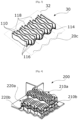
- FIG. 3 is a schematic perspective view showing a passage path of a heat exchanger according to an embodiment of the invention.
- FIG. 4 is a schematic perspective view of a heat exchanger according to an embodiment of the invention.
- FIG. 1 is a schematic perspective illustration of a single passage channel 10 of a passage path of a heat exchanger according to one embodiment of the invention.
- the channel 10 is formed by an empty space 12 delimited by two plates 14 a and 14 b and two adjacent fins 16 a and 16 b of the heat exchanger.
- the channel extends in a main direction called flow axis 18 , representing the direction in which a fluid passing through the exchanger moves in the channel.
- a section perpendicular to the directional axis forms a planar passage section closed by the walls formed by the two plates 14 a and 14 b and the two adjacent fins 16 a and 16 b .
- the plate 14 a forms a plate called the upper plate and the plate 14 b forms a plate called the lower plate.
- the fins are in contact with these two plates.
- FIG. 2 schematically illustrates two oscillating curves 20 a and 20 b followed respectively by the plates 14 a and 14 b and by the fins 16 a and 16 b , allowing the undulating shape of the passage channel to be obtained.
- the curves here are continuous and sinusoidal, but the curves can take different shapes, for example triangular, etc.
- the curves are oscillating.
- the two curves oscillate and are periodic (that is to say, of constant frequency and of constant maximum and minimum amplitude between each period).
- the first oscillating curve 20 a represents the oscillation applied to the plates 14 a and 14 b and the second curve 20 b represents the oscillation applied to the fins 16 a and 16 b .
- the combination of the two curves 20 a and 20 b at any point corresponds to a generatrix representing the circulation of the fluid in the passage channel 10 .
- the curves here oscillate about the flow axis, but can oscillate in different directions, as shown in FIG. 3 .
- FIG. 3 shows a path 30 for the passage of a heat exchanger according to one embodiment of the invention.
- a passage path 30 comprises several passage channels 110 and allows a fluid to flow, the fluid passing through the various passage channels 110 of the passage path 30 .
- the passage path is formed by two plates (only one plate 114 being visible in the figure) and a plurality of fins 116 , so as to compose the various channels 110 all oriented along axes 118 of parallel directions.
- one of the curves 20 c followed by the plates forming the passage channels 110 is comprised in a plane orthogonal to the mean plane 32 of the plate 114 and thus forms the oscillating curve followed by the plate.
- the curve 20 c oscillates around the mean plane 32 and therefore influences all the channels.
- each fin of the passage channels 110 is comprised in a plane comprising the directional axis of each passage channel 110 .
- FIG. 4 shows a heat exchanger 200 according to one embodiment of the invention.
- the heat exchanger comprises four passage paths, two passage paths 210 a and 210 b being intended for a first fluid and two passage paths 220 a and 220 b intended for a second fluid.
- the passage paths are arranged alternately so as to allow heat exchange between the first and the second fluid.
- the passage paths are arranged so that the flow axes are substantially perpendicular, so as to form a cross-pass interchange.
Landscapes
- Engineering & Computer Science (AREA)
- Physics & Mathematics (AREA)
- Thermal Sciences (AREA)
- Mechanical Engineering (AREA)
- General Engineering & Computer Science (AREA)
- Heat-Exchange Devices With Radiators And Conduit Assemblies (AREA)
Abstract
-
- characterized in that each plate extends along a non-planar surface following at least a first oscillating curve, and each fin further following at least one second oscillating curve along at least one second main direction, in such a way that each passage path allows the fluid to flow in the closed space along a fluid direction defined by a generatrix that is a combination at least of the first oscillating curve and the second oscillating curve.
Description
-
- characterized in that each plate extends along a non-planar surface defined between the fluid inlet and the fluid outlet of the associated passage path, said non-planar surface following at least one first oscillating curve along at least one first main direction around an average surface of the plate, and in that each fin comprises an upper edge configured to be in contact with one of the adjacent plates, called upper plate, and a lower edge configured to be in contact with the other adjacent plate, called lower plate, each fin further following at least one second oscillating curve in at least one second main direction around an average surface of the fin, so that each passage path allows the fluid to flow in the closed space along a fluid direction between the fluid inlet and the fluid outlet, called the flow axis, defined at any point of the curve by a generatrix that is a combination at each point at least of the first oscillating curve and of the second oscillating curve.
-
- the first curve and the second curve have the following characteristics:
0.1<γ<1
0.2<ε<5 - with γ being equal to the mean amplitude of the curve divided by the mean period of the curve, and ε being equal to the mean pitch of the curve divided by the amplitude of the curve.
- the first curve and the second curve have the following characteristics:
Claims (11)
−0.1<γ<1
−0.2<ε<5
Applications Claiming Priority (3)
| Application Number | Priority Date | Filing Date | Title |
|---|---|---|---|
| FR1915230 | 2019-12-20 | ||
| FR1915230A FR3105387B1 (en) | 2019-12-20 | 2019-12-20 | HEAT EXCHANGER WITH OPTIMIZED FLUID PASSAGES |
| PCT/FR2020/052436 WO2021123597A1 (en) | 2019-12-20 | 2020-12-15 | Heat exchanger having optimized fluid passages |
Publications (2)
| Publication Number | Publication Date |
|---|---|
| US20230023640A1 US20230023640A1 (en) | 2023-01-26 |
| US12203710B2 true US12203710B2 (en) | 2025-01-21 |
Family
ID=69811322
Family Applications (1)
| Application Number | Title | Priority Date | Filing Date |
|---|---|---|---|
| US17/783,068 Active 2041-08-01 US12203710B2 (en) | 2019-12-20 | 2020-12-15 | Heat exchanger having optimized fluid passages |
Country Status (6)
| Country | Link |
|---|---|
| US (1) | US12203710B2 (en) |
| EP (1) | EP4078058B1 (en) |
| CN (1) | CN114829863A (en) |
| ES (1) | ES3010318T3 (en) |
| FR (1) | FR3105387B1 (en) |
| WO (1) | WO2021123597A1 (en) |
Citations (24)
| Publication number | Priority date | Publication date | Assignee | Title |
|---|---|---|---|---|
| US2567030A (en) * | 1947-07-11 | 1951-09-04 | Air Maze Corp | Filter panel |
| US2764257A (en) * | 1953-08-19 | 1956-09-25 | Air Maze Corp | Edge filter panel with uneven face |
| US3982981A (en) * | 1972-12-07 | 1976-09-28 | Nissan Motor Co., Ltd. | Unitary honeycomb structure and method of making it |
| US4333749A (en) * | 1980-10-24 | 1982-06-08 | The Marley Company | Drift eliminator structure for counterflow water cooling tower |
| US4460388A (en) | 1981-07-17 | 1984-07-17 | Nippon Soken, Inc. | Total heat exchanger |
| US4589983A (en) * | 1981-11-02 | 1986-05-20 | Donaldson Company, Inc. | Fluid filtering device |
| US4724902A (en) * | 1985-08-06 | 1988-02-16 | Rohm Gmbh Chemische Fabrik | Plate heat exchanger |
| US5010594A (en) * | 1989-06-27 | 1991-04-30 | Japan Air Lines Co., Ltd. | Dampening mask for use in aircraft |
| US6273938B1 (en) * | 1999-08-13 | 2001-08-14 | 3M Innovative Properties Company | Channel flow filter |
| US7159649B2 (en) * | 2004-03-11 | 2007-01-09 | Thermal Corp. | Air-to-air heat exchanger |
| US7168482B2 (en) * | 2003-02-03 | 2007-01-30 | Lg Electronics Inc. | Heat exchanger of ventilating system |
| US7452589B2 (en) * | 1999-09-28 | 2008-11-18 | L&P Property Management Company | Convoluted fiber pad |
| US20080283476A1 (en) * | 2007-05-14 | 2008-11-20 | Global Finishing L.L.C. | Fluid filter and filtering method |
| US8021466B2 (en) * | 2008-03-18 | 2011-09-20 | Carpenter Co. | Fluid flow filter and method of making and using |
| US20120043064A1 (en) * | 2009-04-28 | 2012-02-23 | Mitsubishi Electric Corporation | Total heat exchange element |
| US9630132B2 (en) * | 2014-07-01 | 2017-04-25 | Caterpillar Inc. | Fluid filtering system |
| US20180003447A1 (en) | 2014-11-04 | 2018-01-04 | Valeo Systemes Thermiques | Heat-exchange element suitable for a heat exchange between first and second fluids, an exchanger core including the heat-exchange element and a heat exchanger including the exchanger core |
| US20180195424A1 (en) | 2015-06-30 | 2018-07-12 | Tokyo Radiator Mfg. Co., Ltd. | Inner Fin for Heat Exchanger |
| JP6642603B2 (en) * | 2018-02-28 | 2020-02-05 | 株式会社富士通ゼネラル | Bulkhead heat exchanger |
| US20200166293A1 (en) * | 2018-11-27 | 2020-05-28 | Hamilton Sundstrand Corporation | Weaved cross-flow heat exchanger and method of forming a heat exchanger |
| US20200217596A1 (en) * | 2018-11-07 | 2020-07-09 | Borgwarner Emissions Systems Spain, S.L.U. | Fin Body For A Heat Exchange Tube |
| US20220316807A1 (en) * | 2021-03-30 | 2022-10-06 | Mitsubishi Electric Us, Inc. | Air-to-air heat recovery core and method of operating the same |
| US20230221076A1 (en) * | 2020-07-13 | 2023-07-13 | Gaontech Co., Ltd. | Method for manufacturing counter flow total heat exchanger |
| US20230235916A1 (en) * | 2020-08-11 | 2023-07-27 | Mitsubishi Electric Corporation | Total heat exchange element and ventilator |
Family Cites Families (9)
| Publication number | Priority date | Publication date | Assignee | Title |
|---|---|---|---|---|
| SE423750B (en) * | 1977-01-14 | 1982-05-24 | Munters Ab Carl | DEVICE EXCHANGER FOR SENSIBLE AND / OR LATENT TRANSMISSION |
| JP3139681B2 (en) * | 1999-05-31 | 2001-03-05 | 春男 上原 | Condenser |
| JP3697523B2 (en) * | 2003-10-10 | 2005-09-21 | 国立大学法人 東京大学 | Regenerative heat exchanger and regenerative heat exchange method |
| DE202005009948U1 (en) * | 2005-06-23 | 2006-11-16 | Autokühler GmbH & Co. KG | Heat exchange element and thus produced heat exchanger |
| JPWO2010125643A1 (en) * | 2009-04-28 | 2012-10-25 | 三菱電機株式会社 | Heat exchange element |
| US11112183B2 (en) * | 2016-01-14 | 2021-09-07 | Hamilton Sundstrand Corporation | Heat exchanger channels |
| GB2565143B (en) * | 2017-08-04 | 2021-08-04 | Hieta Tech Limited | Heat exchanger |
| CN208155134U (en) * | 2018-05-15 | 2018-11-27 | 郑州大学 | A kind of novel plate-fin heat exchanger fin |
| CN109883238A (en) * | 2019-03-08 | 2019-06-14 | 西安交通大学 | A kind of plate fin type heat exchanger core and its fin structure |
-
2019
- 2019-12-20 FR FR1915230A patent/FR3105387B1/en active Active
-
2020
- 2020-12-15 CN CN202080087136.4A patent/CN114829863A/en active Pending
- 2020-12-15 US US17/783,068 patent/US12203710B2/en active Active
- 2020-12-15 WO PCT/FR2020/052436 patent/WO2021123597A1/en not_active Ceased
- 2020-12-15 ES ES20845201T patent/ES3010318T3/en active Active
- 2020-12-15 EP EP20845201.1A patent/EP4078058B1/en active Active
Patent Citations (24)
| Publication number | Priority date | Publication date | Assignee | Title |
|---|---|---|---|---|
| US2567030A (en) * | 1947-07-11 | 1951-09-04 | Air Maze Corp | Filter panel |
| US2764257A (en) * | 1953-08-19 | 1956-09-25 | Air Maze Corp | Edge filter panel with uneven face |
| US3982981A (en) * | 1972-12-07 | 1976-09-28 | Nissan Motor Co., Ltd. | Unitary honeycomb structure and method of making it |
| US4333749A (en) * | 1980-10-24 | 1982-06-08 | The Marley Company | Drift eliminator structure for counterflow water cooling tower |
| US4460388A (en) | 1981-07-17 | 1984-07-17 | Nippon Soken, Inc. | Total heat exchanger |
| US4589983A (en) * | 1981-11-02 | 1986-05-20 | Donaldson Company, Inc. | Fluid filtering device |
| US4724902A (en) * | 1985-08-06 | 1988-02-16 | Rohm Gmbh Chemische Fabrik | Plate heat exchanger |
| US5010594A (en) * | 1989-06-27 | 1991-04-30 | Japan Air Lines Co., Ltd. | Dampening mask for use in aircraft |
| US6273938B1 (en) * | 1999-08-13 | 2001-08-14 | 3M Innovative Properties Company | Channel flow filter |
| US7452589B2 (en) * | 1999-09-28 | 2008-11-18 | L&P Property Management Company | Convoluted fiber pad |
| US7168482B2 (en) * | 2003-02-03 | 2007-01-30 | Lg Electronics Inc. | Heat exchanger of ventilating system |
| US7159649B2 (en) * | 2004-03-11 | 2007-01-09 | Thermal Corp. | Air-to-air heat exchanger |
| US20080283476A1 (en) * | 2007-05-14 | 2008-11-20 | Global Finishing L.L.C. | Fluid filter and filtering method |
| US8021466B2 (en) * | 2008-03-18 | 2011-09-20 | Carpenter Co. | Fluid flow filter and method of making and using |
| US20120043064A1 (en) * | 2009-04-28 | 2012-02-23 | Mitsubishi Electric Corporation | Total heat exchange element |
| US9630132B2 (en) * | 2014-07-01 | 2017-04-25 | Caterpillar Inc. | Fluid filtering system |
| US20180003447A1 (en) | 2014-11-04 | 2018-01-04 | Valeo Systemes Thermiques | Heat-exchange element suitable for a heat exchange between first and second fluids, an exchanger core including the heat-exchange element and a heat exchanger including the exchanger core |
| US20180195424A1 (en) | 2015-06-30 | 2018-07-12 | Tokyo Radiator Mfg. Co., Ltd. | Inner Fin for Heat Exchanger |
| JP6642603B2 (en) * | 2018-02-28 | 2020-02-05 | 株式会社富士通ゼネラル | Bulkhead heat exchanger |
| US20200217596A1 (en) * | 2018-11-07 | 2020-07-09 | Borgwarner Emissions Systems Spain, S.L.U. | Fin Body For A Heat Exchange Tube |
| US20200166293A1 (en) * | 2018-11-27 | 2020-05-28 | Hamilton Sundstrand Corporation | Weaved cross-flow heat exchanger and method of forming a heat exchanger |
| US20230221076A1 (en) * | 2020-07-13 | 2023-07-13 | Gaontech Co., Ltd. | Method for manufacturing counter flow total heat exchanger |
| US20230235916A1 (en) * | 2020-08-11 | 2023-07-27 | Mitsubishi Electric Corporation | Total heat exchange element and ventilator |
| US20220316807A1 (en) * | 2021-03-30 | 2022-10-06 | Mitsubishi Electric Us, Inc. | Air-to-air heat recovery core and method of operating the same |
Also Published As
| Publication number | Publication date |
|---|---|
| WO2021123597A1 (en) | 2021-06-24 |
| ES3010318T3 (en) | 2025-04-02 |
| EP4078058B1 (en) | 2025-02-05 |
| EP4078058A1 (en) | 2022-10-26 |
| FR3105387B1 (en) | 2021-11-26 |
| FR3105387A1 (en) | 2021-06-25 |
| CN114829863A (en) | 2022-07-29 |
| US20230023640A1 (en) | 2023-01-26 |
Similar Documents
| Publication | Publication Date | Title |
|---|---|---|
| EP3663694B1 (en) | Heat exchanger riblet features for improved manufacturability and performance | |
| AU2017202129B2 (en) | Heat Exchanger and Method of Manufacturing a Heat Exchanger | |
| EP1061319B1 (en) | Fluid conveying tube and use of the same in a vehicle cooler | |
| US20200298652A1 (en) | Thermal management system and method | |
| EP3640574B1 (en) | Counter-flow heat exchanger with helical passages | |
| EP2108911B1 (en) | Heat exchanger | |
| US11118848B2 (en) | Heat-exchanging plate, and plate heat exchanger using same | |
| EP3604998A1 (en) | Counter flow heat exchanger | |
| US20130153184A1 (en) | Heat exchanger | |
| US20050230094A1 (en) | Tube structure of multitubular heat exchanger | |
| AU2020204326B2 (en) | Thermal management system and method | |
| CN119245382A (en) | Indirect heat exchanger | |
| US20200370836A1 (en) | Heat exchanger comprising a multi-channel distribution element | |
| JPS6334393B2 (en) | ||
| EP4141372A2 (en) | A plate of plate heat exchangers | |
| US12203710B2 (en) | Heat exchanger having optimized fluid passages | |
| US20220412668A1 (en) | Wavy adjacent passage heat exchanger core and manifold | |
| US20200041218A1 (en) | Plate heat exchanger | |
| WO2019234756A1 (en) | A plate of plate heat exchangers | |
| JP4638583B2 (en) | Fluid transport tube and automotive cooler comprising the tube | |
| EP4108458A1 (en) | Wavy adjacent passage heat exchanger core | |
| WO2019020624A1 (en) | Heat exchanger and thermal system for a motor vehicle | |
| JPWO2019234756A5 (en) |
Legal Events
| Date | Code | Title | Description |
|---|---|---|---|
| FEPP | Fee payment procedure |
Free format text: ENTITY STATUS SET TO UNDISCOUNTED (ORIGINAL EVENT CODE: BIG.); ENTITY STATUS OF PATENT OWNER: LARGE ENTITY |
|
| AS | Assignment |
Owner name: LIEBHERR-AEROSPACE TOULOUSE SAS, FRANCE Free format text: ASSIGNMENT OF ASSIGNORS INTEREST;ASSIGNORS:INGENITO, JOHANNA;ANGELIQUE, ROMAIN;BONNIVARD, FLORIAN;AND OTHERS;SIGNING DATES FROM 20220607 TO 20220623;REEL/FRAME:061451/0027 |
|
| STPP | Information on status: patent application and granting procedure in general |
Free format text: DOCKETED NEW CASE - READY FOR EXAMINATION |
|
| STPP | Information on status: patent application and granting procedure in general |
Free format text: NON FINAL ACTION MAILED |
|
| STPP | Information on status: patent application and granting procedure in general |
Free format text: RESPONSE TO NON-FINAL OFFICE ACTION ENTERED AND FORWARDED TO EXAMINER |
|
| STPP | Information on status: patent application and granting procedure in general |
Free format text: NOTICE OF ALLOWANCE MAILED -- APPLICATION RECEIVED IN OFFICE OF PUBLICATIONS |
|
| ZAAB | Notice of allowance mailed |
Free format text: ORIGINAL CODE: MN/=. |
|
| STPP | Information on status: patent application and granting procedure in general |
Free format text: PUBLICATIONS -- ISSUE FEE PAYMENT VERIFIED |
|
| STCF | Information on status: patent grant |
Free format text: PATENTED CASE |