US12201165B2 - Adjustable, cleavage enhancing undergarment system - Google Patents
Adjustable, cleavage enhancing undergarment system Download PDFInfo
- Publication number
- US12201165B2 US12201165B2 US17/723,902 US202217723902A US12201165B2 US 12201165 B2 US12201165 B2 US 12201165B2 US 202217723902 A US202217723902 A US 202217723902A US 12201165 B2 US12201165 B2 US 12201165B2
- Authority
- US
- United States
- Prior art keywords
- paddle
- force
- generating member
- wearer
- breast
- Prior art date
- Legal status (The legal status is an assumption and is not a legal conclusion. Google has not performed a legal analysis and makes no representation as to the accuracy of the status listed.)
- Active, expires
Links
Images


Classifications
-
- A—HUMAN NECESSITIES
- A41—WEARING APPAREL
- A41C—CORSETS; BRASSIERES
- A41C3/00—Brassieres
- A41C3/0028—Brassieres with size and configuration adjustment means
-
- A—HUMAN NECESSITIES
- A41—WEARING APPAREL
- A41C—CORSETS; BRASSIERES
- A41C3/00—Brassieres
- A41C3/005—Brassieres specially adapted for specific purposes
-
- A—HUMAN NECESSITIES
- A41—WEARING APPAREL
- A41C—CORSETS; BRASSIERES
- A41C3/00—Brassieres
- A41C3/06—Strapless brassieres
- A41C3/065—Strapless brassieres attached directly to the body, e.g. by means of adhesive
Definitions
- the present invention relates generally to the field of undergarment systems worn by women, and particularly to such a system having an open front and an enhancing element that adjustably increases the cleavage, as well as give the appearance of lift by plumping the breasts of a woman wearing the undergarment.
- Bras have been used to cover, support and enhance a woman's breasts for many years. Bras typically have over-the-shoulder straps, cups for each breast, a strap or straps around the back and a strap connecting the cups in the front.
- Bras are typically worn under clothing and are not visible to others. Over the years, the bra has undergone many changes. For example, while the bra was at one time a method of concealment, it has more recently become a tool to enhance the shape lines of the wearer. This has been evidenced in recent years by the extreme popularity of cleavage enhancing bras. A trend in women's clothes has been toward more revealing clothes, driving a similar trend in bras to be smaller, thinner and less obtrusive. For example, strapless bras are useful for women wearing clothing that reveals the upper part of the shoulders.
- bras which are designed to enhance a wearer's cleavage are either not structured to be worn or unable to work effectively when worn under certain elegant, stylish garments which are strapless, or which offer a lowcut plunging neckline or a bare back look.
- Lowcut dresses with plunging necklines that reveal the area on the chest of a woman between the breasts must sometime be worn braless. Typically, this exposes a gap between the breasts of the wearer and does not provide desired cleavage or extra enhancement of actual breast size.
- bras or other types of undergarments that not only enhance the wearer's breast size and cleavage, but which further can effectively do so without the use of straps about the shoulders or the wearer's back or beneath the breasts of the wearer.
- the '132 patent discloses a frontless, backless and strapless braette design adapted to provide enhanced breast size appearance and cleavage of the breasts of a wearer by including a first compression “pad” (in the present invention described hereinafter, this component is called a “paddle” or “compression paddle”) having an inner and outer surface, the inner surface being contoured to engage the outer side of one breast of the wearer, a second compression pad having an inner and an outer surface, the inner surface being contoured to engage the outer side of the other breast of the wearer, and a force-generating member having first and second ends connected to said first and second compression pads, respectively, and extending downwardly, away from the breast of the wearer toward the abdomen of the wearer to push the breasts of the wearer toward each other to provide the enhanced breast size appearance and cleavage.
- a first compression “pad” in the present invention described hereinafter, this component is called a “paddle” or “compression paddle”
- a first compression pad in the present invention
- FIG. 1 shows a perspective view of a braette according to that invention having a force-generating member 22 that is preferably a shaped, deformable metal beam or rod having its ends permanently connected to or molded into compression pads 12 and 16 that supply the inward-directed forces to the outer sides of the breasts of the wearer.
- a force-generating member 22 that is preferably a shaped, deformable metal beam or rod having its ends permanently connected to or molded into compression pads 12 and 16 that supply the inward-directed forces to the outer sides of the breasts of the wearer.
- the force-generating member 22 is preferably a beam or rod constructed of metal in this embodiment and more preferably that metal is steel and can be cold rolled steel or spring steel, or if desired, the steel may be heat treated in manners well known to the prior art.
- the function of the force-generating member 22 is to apply an inwardly directed force to the compression pads 10 [sic] and 16 to cause them to push the breasts together and also to provide the appearance of lift to the breasts to enhance the breast size and cleavage. It is therefore an important feature of the present invention that the metal beam or rod retain its resilience so it can be repeatedly used. Also, the wearer may adjust the amount of force to be applied to the breasts by bending the beam or rod.” ('132 patent, col. 3, line 41-line 59, emphasis added.)
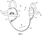
- braette 10 may be adjusted in a number of directions.
- Arrows 30 and 30 ′ indicate that paddles 12 and 16 may be forcibly rotated in the direction shown or in the opposite direction to fit larger or smaller breast sizes, respectively (“rotational adjustment”).
- metal rod 22 may be manually bent outwardly in the direction shown by arrow 32 to reduce the amount of inward force applied to the outer sides of both breasts.
- rod 22 may be bent inwardly-positioning paddles 12 , 16 closer together in order to increase the force on the breasts to increase the cleavage effect (“compression force adjustment”).
- paddles 12 and 20 may be “splayed” outwardly in the directed shown by arrows 34 , 34 ′ or in the opposite direction (“splay adjustment”).
- two features of the disclosed metal beam force-generating member 22 are resilience and adjustability: resilience, so that it can repeatedly hold the compression pads 10 [sic] and 16 in the same place with the same inward force and orientation use after use; and adjustability, so that the wearer, at an initial set up or “fitting,” can bend the beam member in at least two dimensions, by (a) twisting the ends of the beam connected to the pads so that the pads are rotationally oriented relative to the size and shape of the breasts of the wearer; and (b) bending the beam itself, so that the paddles are more or less pushed together.
- the terminal portions 28 , 30 of metal beam 22 “ . . . are bent at substantially right angles to the longitudinal axis of the metal beam 22 . . . . Such configuration is then totally encapsulated within the molded plastic compression pads 10 [sic] and 16 . By being bent in this manner, the metal beam 22 is securely retained within the compression pads 10 [sic] and 16 at all times.”
- Harris demonstrates approximate degrees of pad rotation appropriate for various breast sizes (e.g., B, C, D, etc.).
- the video also shows the substantial force needed to both rotate the paddles to fit the user and the force needed to bend the metal beam to adjust for cleavage amount.
- the video shows the use and application of soft, shaped pads into which the paddles are inserted in order to create comfort and to compensate for the loss of the natural shape of the outer side of the breasts that are compressed by the paddles.
- each end of the force-generating member preferably terminates in a round, toothed, ratcheted nub or pin.
- female, toothed, ratcheted openings are adapted to removably receive ratcheted nubs or pins of the force-generating member.
- the bra system of the present invention includes improved compression force adjustment mechanisms by disclosing a force-generating member having an extendible crossbar to enabling its length to be adjusted. This enables the bra system to be easily made narrower or wider to create more or less cleavage action on the breasts.
- the present invention also discloses improved pad technologies that provide a truly seemless look to the breasts when worn under clothing.
- FIG. 1 is a diagrammatic perspective view of a cleavage-enhancing braette as disclosed in the prior art
- FIG. 2 is a partial cutaway perspective view of an illustrative rendition of part of a Misses KissesTM “braette” in the prior art
- FIG. 5 is an illustrative perspective view of one selectably rotatable paddle solution for the system show in FIG. 4 in accordance with an embodiment of the present invention
- FIGS. 6 A- 6 D show illustrative views of an adjustable, ratcheted male-female joint employed at a paddle-bar end junction enabling precise paddle rotational adjustment in accordance with one embodiment of the present invention
- FIGS. 7 A and 7 B show further details and alternative selectably rotatable paddle solution disclosed in FIGS. 6 A- 6 D ;
- FIGS. 8 A and 8 B show alternative options that may be implemented for the selectably rotatable paddle solution according to embodiments of the invention
- FIGS. 9 A and 9 B show one preferred embodiment of a bar width adjuster in unassembled and assembled states, respectively, in accordance with the present invention
- FIGS. 10 A and 10 B show alternative embodiments of a bar width adjuster in accordance with the present invention
- FIG. 11 shows a metal-plastic hybrid compression bar embodiment of the present as an alternative to the inventive design shown in FIG. 4 ;
- FIG. 12 shows an optional features for a metal-plastic hybrid solution according to embodiments of the invention.
- FIG. 13 shows another optional inventive solution to the paddle-bar interface in accordance with another embodiment of the present invention.
- FIG. 14 shows yet another inventive optional adjustable feature of the bra of the present invention
- FIG. 15 shows an illustrative diagram of a volumizing pad in accordance with one embodiment of the present invention.
- FIG. 16 shows an illustrative diagram of a paddle with the disposition of anti-skid material attached thereon
- FIGS. 17 A- 17 C conceptually shows component layering options at the paddle/pad interfaces in accordance with embodiments of the present invention.
- FIGS. 18 A- 18 D show the design of an improved pad in accordance with embodiments of the present invention.
- FIG. 4 shows a front, partial cutaway view of an illustrative, frontless, backless and strapless bra system 100 that functions to support a wearer's breasts while exposing front, back and shoulder portions of her body, and to provide an enhanced cleavage look.
- system 100 combines two optional inventive features of user adjustability, namely, improved rotational adjustability and improved compression force adjustability.
- system 100 comprises four basic components, in the present embodiment preferably all made of lightweight but sufficiently sturdy injection-molded plastic: right breast paddle 102 , left breast paddle 122 , right support bar 130 and left support bar 140 .
- system 100 may optionally only provide the improved paddle rotational adjustability feature, in which case, a single force-generating support bar may replace the two support bar components 130 , 140 .
- the support bars 130 , 140 may optionally be replaced with a single bar or wire comprising, a pliable metal material as disclosed in the prior art, enabling the bar to offer conventional compression force adjustability, namely, by forcibly bending the bar as disclosed in the '132 patent.
- the wire may not comprise the entire bar, but rather only a portion of the bar, with the wire ends connecting to other bar components that connect to paddles 102 , 122 .
- right breast paddle 102 includes outer surface 104 and inner surface 106 (not shown) that when in use presses against the outer side of the user's right breast.
- Left breast paddle 122 has outer surface 124 and inner surface 126 (not shown) that when in use presses against the outer side of the left breast.
- Conically tapering cavities 108 , 128 extend into the bodies of paddles 102 , 122 respectively from openings 106 , 126 , respectively.
- Support bar components 130 , 140 are, but need not be, elbow shaped and adjustably connect with each other at junction 150 as discussed further below.
- Rotational Adjustability “Conical Friction”—In one embodiment of the rotational adjustability feature of the present invention, as seen in FIG. 4 , when assembling system 100 together, paddles 102 , 122 can be selectively fixed at desired angles relative to the plane defined by the assembled support bars 130 , 140 (and the front chest and torso of the wearer) by simply pressing support bars 130 , 140 into its mating paddle cavity 108 , 128 at those desired angles. The paddle positions are kept from freely rotating about the axes defined their mating pegs based on the friction forces caused by the engagements of the pegs against the inner walls of the cavities into which they are inserted.
- pegs 132 , 142 preferably are conically tapered moving to their ends, and correspondingly, peg-receiving cavities 108 , 128 are likewise conically tapered, each with a depth that is slightly deeper than the length of its mating peg.
- the deeper conical pin 132 is pressed into paddle cavity 108 , the greater the wall friction created between outer surface of pin 132 and the inner circumference of the cavity 108 .
- the conical pin outer surface, its mating cavity inner circumference surface or both may have finishes that are not smooth or may include coatings that provide the desired coefficient of friction between the components when assembled.
- the rotational angle of a paddle may be easily adjusted by simply pulling the paddle off its pin and reinserting it at a different angle. This enables the user to achieve a perfect fit with minimal effort.
- the disengagement of the peg from the cavity can be achieved by pulling the two apart only a small distance.
- This pulling apart can be achieved by hand or by a mechanical mechanism designed into the peg and cavity system such as a lever, button, or twisting spacer mechanism.
- a mechanism such as a twisting spacer will give the user an easy method of reducing the friction so the adjustment can be made with minimal effort.
- the mechanism when twisted the other way will then snap the peg and cavity together more tightly and freeze the paddle at the desired angle with respect to the front of the user.
- paddle 102 may include a downwardly oriented arrow 154 at its open end 138
- support bar 130 may include a set of letters, say A through F around its circumference (shown here in partial view A through C), at a location that aligns with arrow 154 when bar 130 is inserted into paddle 102 .
- the user when the user assembles paddle 102 onto bar 130 , before pressing and fixing them together, she can rotate the paddle so that arrow 154 aligns with the letter (or a number) that corresponds to her breast size. This may help eliminate the trial-and-error guesswork involved when setting up system 100 for the user, or at least reduce the number of times the user will need to adjust the paddles to obtain a good fit.
- FIGS. 6 A- 6 C disclose another rotational adjustability design, namely a teeth-to-teeth securing solution. This solution may replace or may preferably complement the “conical friction” embodiment disclosed in connection with FIG. 4 . Similar to that design, pin 202 of force-generating bar component 200 ( FIG. 6 A ) is inserted into paddle 230 cavity 240 ( FIG. 6 C ) at a desire rotational angle. But now, as seen in the FIG. 6 B birds-eye, cross-sectional view of pin 202 at 2 - 2 , pin 202 has teeth 204 disposed around its tapered circumference.
- the interior circumference of the wall defined by cavity 240 is disposed with mating teeth 242 .
- teeth 202 and 242 interlock, as seen in illustrative cross-sectional view of FIG. 60 , and hold the paddle at the desired rotational angle relative to pin. This design effectively “locks” the paddle in place and prevents unwanted rotation under pressure in use.
- FIGS. 7 A and 7 B One advantage of this design is that rotational adjustment of a paddle relative to its mating pin can be made without separating or lifting the paddle away from the peg. This is demonstrated in the examples shown FIGS. 7 A and 7 B .
- mating teeth 202 , 242 are straight so that paddle 230 may be rotated around pin 202 of bar 200 in either a clockwise or counterclockwise direction with precision “clicks,” as the mating teeth forcibly pass over each other.
- the number of teeth 202 , 242 on the components are a matter of design choice, with the greater the number of teeth corresponding to more positional granularity—i.e., each rotational “click” corresponds to a smaller angular displacement—and the fewer the teeth, the coarser the angular displacement.
- the conical friction design shown in FIGS. 4 and 6 need not be present in this teeth-to-teeth embodiment. However, it still may be desired to have the conical taper in this design as well and use the techniques described for the friction approach depending on the overall design goals Instead, pin 202 and its mating cavity 240 may be cylindrical.
- paddle 230 may be clamped to pin 202 using any suitable technique as will be understood by those skilled in the art.
- a horizontally disposed set screw or regular screw may be provided in paddle 230 to enable the user to securely tighten paddle 230 to pin 202 .
- interlocking teeth 202 b and 242 a may be biased at an angle off the horizontal creating a one-way, “sawtooth” ratchet effect as shown.
- paddle 230 will rotate around pin 202 in one direction when the user applies sufficient rotational force, but will lock—not rotate—in the reverse direction.
- paddle 230 could be difficult to rotate even in the intended rotational direction.
- the pin ends of the force generating member that is the wire-sleeve combination
- the pin ends of the force generating member can optionally be made in such a way that each wire end can be inserted and removed from its mating sleeve so that different wire bars can be used with the same paddles.
- the wire bars can be made to be replaceable while the sleeve remains in (or is pre-assembled into) the paddle cavity as part of the paddle assembly.
- the bra system may be sold as kit, with interchangeable wires of different shapes and depths.
- such a kit can come with three force-generating wire components one that, when assembled creates a shallow plunge bra system, another wire that creates a mid-plunge system and a third that creates a deep plunge bra system.
- FIGS. 8 A and 8 B show pin 300 of a compression bar as a simple post inserted into paddle cavity.
- Pin 300 may be a simple cylinder that is free to rotate in the cavity and may be set in place at the desired angular rotation simple by a screw, such as a set screw.
- pin 300 may be multi-sided, such as in the shape of a hexagon with a corresponding hexagonal mating cavity. The user simply inserts pin 300 into paddle cavity at a desire détente angle.
- Pin 300 may be plastic or metal.
- snap ring 310 acts to snap pin 300 into its mating cavity.
- FIG. 8 A shows pin 300 of a compression bar as a simple post inserted into paddle cavity.
- pin 300 may be a simple cylinder that is free to rotate in the cavity and may be set in place at the desired angular rotation simple by a screw, such as a set screw.
- pin 300 may be multi-sided, such as in the shape of a hexagon with a corresponding hexagonal mating cavity. The user simply inserts pin 300
- pin 350 is a threaded post. Pin 350 then screws into paddle cavity with a mating threaded inner circumference.
- a stop nut that allows paddle angular adjustment to a desired angle
- a horizontal set screw may also be used in this embodiment to help prevent rotation under pressure. It should be noted that the descriptions contained herein regarding the rotational adjustability do not limit the options only to those described. For example, it can also be envisioned that the pin is part of the paddle, and the cavity is contained in the force-generating member. All of the options and capabilities described previously can be applied to this new configuration except pin and cavity relationship reversed.
- FIGS. 9 A and 9 B show one such embodiment, whereby left bar component 520 having notched holes 522 a - 522 n slides into right bar component 500 having angled-teeth like structures 502 a - 502 n . Each tooth 502 snaps into a notched hole 522 as it passes over it as the two components are pressed together.
- left bar component 520 may have a visible numbering system printed on it, 1 . . . n, with each number corresponding a translational position of the bar system, with the higher the number corresponding to a greater degree of compression force.
- sliding component 520 into component 500 the maximum distance, such that tooth 520 n snaps in hole 522 a and the tooth 520 (n ⁇ 1) is notched into hole 522 b and so forth may results in shortest compression bar that provides the greatest compression force on the wearer's breasts.
- the teeth 520 are biased as shown, translational adjustment in this embodiment can only be made to move in one direction—inward, or from longer to shorter bar system.
- a release mechanism such as a twisting action that releases all engaged teeth 502 a - 502 i by twisting the components and pulling them apart.
- FIGS. 10 A and 10 B show other options for adjusting the length of the bar component system.
- FIG. 10 A contemplates a simple screw-in design, wherein left bar component 520 b is threaded and screws into the threaded cavity of right bar component 500 b . The user simply stops screwing the components together at the desired component pair length corresponding to the desire compression force.
- FIG. JOB shows another simple design whereby left bar component 520 c is inserted into the cavity of right bar component 500 c and a trap pin 502 c is inserted through holes in each component to secure them together.
- Other options are contemplated and are within the scope of the present invention.
- Teen skilled in the art will note that there are many known mechanisms of creating translation in a plastic or metal bar.
- the present invention is not limited to using one class of material for all components.
- plastic components may be desirable from the perspectives of producibility (plastic extrusion), weight (low) and cost (low)
- these designs may also incorporate metal components to improve the strength and integrity of some aspects of the design.
- the base configuration bra system shown in FIG. 4 may be modified with a modified plastic support bar structure that incorporates a metal or other stiff material such as carbon steel, pin subassembly 600 a , 600 b through the inner portion of support bar components 130 ′, 140 ′.
- this subassembly may comprise a first thin steel tube 600 a that receives steel pin 600 b , providing an increase in the strength of the bar, and, as seen, enabling a potentially very large reduction in the overall diameter of the horizontal mating parts of bar components 130 ′, 140 ′.
- pin 600 b corresponding slides into or away from bar 600 a , enabling the bra system to provide the desired compression force on the outer sides of the breasts.
- the any of the mechanisms shown in FIGS. 9 and 10 can be used to translate the length of the bar, while the steel pin subassembly creates the strength required to make the bar much smaller than would otherwise be possible with plastic alone.
- compression bar assembly 700 includes a single stiff metal wire 710 (thus, this configuration does not offer translational adjustment but instead depends on the bending of the wire bar to achieve width adjustment), with an end 712 that is fixed (preferably during manufacturing) into conically-shaped plastic paddle pin 714 . Then, typically during user assembly, pin 714 is inserted into the cavity of its mating paddle and rotationally adjusted using any of the configurations discussed above in connection with FIGS. 4 - 8 .
- metal wire 710 is configured with a “squiggle-like” bend 720 at the location where wire 710 is wedged into plastic pin 714 as shown.
- This squiggle configuration stabilizes and provides torque control at the metal-plastic interface to help prevent slipping when a user forcibly rotates a paddle.
- the plastic pin is molded directly onto the wire and the “squiggle” is employed to create a strong connection of the wire to the pin thus preventing rotation or translation of the plastic pin relative to the wire. It should be noted that the anti-rotation function of the squiggle can be achieved on other ways as well.
- Approaches such as flattening the bar, splitting the bar or otherwise deforming the bar before molding the wire into the pin assembly may be used to create the means to prevent rotation of the pin assembly with respect to the wire during use of the bra due to torque generated on the paddle during use, translating to the plastic pin and then to the wire.
- One further option to the configuration shown in FIG. 12 may be whereby wire 710 is extended through pin 714 and sticks out of its top a short distance. In this case, where pin 714 is inserted into paddle 102 , pin 714 will connect further into paddle 102 improving the transfer of force from paddle 102 to wire 710 within force-generating assembly 700 .
- a further configuration shown in FIG. 13 may complement or replace the embodiment shown in FIG. 12 .
- metal sleeve 750 having multiple teeth 752 a - 752 n is inserted and fixed into paddle cavity 760 .
- a metallic (or other) wire may also have surface conditioning on the sections that are pressed into paddle cavity 760 , such that the conditioned sections engage teeth 752 a - 752 n .
- a metal-to-metal ratchet interface is created between the conditioned bar and the metal sleeve 740 .
- the end of the bar may be held tightly in the paddle cavity 760 via a press fit with the friction generated between the insert and the cavity wall.
- the present invention also discloses a means for adjusting the “splay” of the paddle relative to the compression bar.
- Splay is the amount of outward rotation of the paddle relative to the part of the bar that crosses across the user's body. This is shown conceptually in the partial bar view of FIG. 14 , where the bend 802 of compression bar 800 includes a selectable rotation mechanism 810 , similar in concept to the rotatable ratchet design discussed above.
- a volumizing pad 900 is shown having an inner side 910 that interfaces directly with the breasts of the wearer, and outer side 920 that would generally contact the inner side of clothing of the wearer.
- Antiskid or antislip material may optionally be used by the present invention and it would be attached to the inner side of the volumizing pad.
- pad 900 has a hollow pocket 912 between inner side 910 and outer side 920 into which a paddle is inserted via pad slot 930 . The paddle may be shifted inside the pocket to affect the best fit of the volumizing pad to the shape of the breast.
- inner surface 1002 of paddle 1000 may optionally have an anti-skid material 1010 applied to it in order to prevent slippage of pad 900 with respect to paddle 1000 when the paddle is inserted to pad 900 via slot 130 and positioned on it.
- a volumizing pad may also be fixed directly to the outside of paddle 1000 without the pocket configuration shown in FIG. 15 , in a number of ways.
- the inner side of the pad may be glued, “Velcroed”, or secured using a specialized connection between the pad and the outer side of paddle, such as a slot or a hook formed directly into the plastic paddle outside, or some other connection mechanism as will be understood by those skilled in the art.
- anti-skid or anti-slip material 1010 may be attached to the inner side 1002 of the paddle and can take many forms including but not limited to: a thin slice or sticker of material that is sticky on both sides; a coating added to at minimum the inside of the paddle that remains sticky; a sticky material that can flow some amount that is applied to inside of paddle; or a rough surface on inner side of paddle which can grip the volumizing pad directly.
- This latter embodiment may remove the need for anti-skid material altogether, particularly in cases where the paddle is inserted into the pocket of the volumizing pad.
- sticky material may also be applied to the volumizing pads.
- volumizing pad 900 with pocket 912 in FIG. 15 may take numerous configurations when interfacing with its mating paddle. These layered configurations are symbolically disclosed in FIGS. 17 A, 17 B and 17 C .
- a novel volumizing pad with a paddle inserted therein has a voluming pad portion whose volumizing outer side is designed to round out the look of the compressed breast and engages the clothing the wearer and an inner side, called here “pocket wall” that meets the outer side of the paddle.
- the inner side of the pad is novelly constructed with anti-skid or anti-slip material that is embedded directly into and throughout the pad fabric.
- FIG. 17 B is similar, but with a few changes including the use a separate anti-skid application on the side of the pad that engages the breast. Also, as seen, there may be no need for additional structure to keep the paddle in place relative to the pad into which it is inserted with the use of a high friction paddle that naturally “grabs” the inner pocket walls of the pad.
- FIG. 17 C shows a configuration in which anti-skid material is added to both sides of the inner pocket wall of the pad to achieve the needed “sticking” friction of the pad to both the paddle and the wearer's breast.
- FIGS. 18 A-D disclose a two-piece volumizing pad 1100 that is seamless and completely smooth when worn by a user.
- Pad 1100 comprises a domed, volumizing outer pad component 1102 and a thin inner pad 1104 component having a back side 1104 b , whose outer perimeter is sealed to the outer perimeter of the back side 1102 b of outer pad component 1102 .
- Inner pad 1004 has a slot 1106 disposed across a portion of its body serving (as best shown in FIG. 18 c ) as the insertion point for a paddle.
- pad 1100 When a paddle is first inserted through slot 1106 , pad 1100 may be positioned (rotated) about the paddle in accordance with the volumizing shaped desired by the wearer. In some embodiments, once pad 1100 is positioned relative to its inserted paddle, the frictional force applied by the breast that is being forced inward (to create the cleavage effect) will be sufficient keep the pad from moving relative to its paddle.
- a small sheet of sticking material may be attached to either the back side 1102 b of pad 1100 or the back side 1104 b of thin inner pad 1104 , which will engage and hold either the outer surface of the paddle (in the case of the sticking sheet being on the back side 1002 b ) or the inner surface of the paddle.
- volumizing pad 1100 is novel and inventive in its own right.
- the outer side of volumizing outer pad component 1102 is egg-shaped. This adds great versatility to pad 1100 because it is not only rotatable on a paddle to create the look desired by the wearer's appropriate to her particular breast shape, it is also reversible in the sense that it may be place over either the left breast paddle or right breast paddle.
- a sheet of sticky material 1108 that stuck to the outer side of think inner pad 1004 may be provided to provide a sticky friction for the portion of the breast that engages this inner side of pad 1100 so that pad 1100 does not slide down off the breast when worn.
- sheet 1108 comes with a peel-off cover sheet that is peeled off right before wearing.
- Sheet 1108 may comprise different materials. In one embodiment, it is made from “biogel”, which is highly and repeatedly effective to keep engagement against the skin—even with swimming or dancing.
- sheet 1108 may comprise anti-slip, medical-grade silicon stickers. Sheet 1108 may also include holes across its surface in order to allow the skin to “breath” and sweat.
- the pads of the present invention may be made in any appropriate soft material that provides sufficient volume while being lightweight and comfortable to wear.
- the pads may also be offered in different sizes to match the size of the user's breasts.
- a single Misses Kisses bra kit comprising paddle, compression bar and pad components according to the present invention, four different sized pad sets (or more or less) may be included in one kit covering, for example, petite, regular, large and curvy (extra large) breasts.
Landscapes
- Engineering & Computer Science (AREA)
- Textile Engineering (AREA)
- Corsets Or Brassieres (AREA)
- Prostheses (AREA)
- Undergarments, Swaddling Clothes, Handkerchiefs Or Underwear Materials (AREA)
Abstract
Description
Claims (16)
Priority Applications (6)
| Application Number | Priority Date | Filing Date | Title |
|---|---|---|---|
| US17/723,902 US12201165B2 (en) | 2021-08-27 | 2022-04-19 | Adjustable, cleavage enhancing undergarment system |
| TW111131701A TW202337337A (en) | 2021-08-27 | 2022-08-23 | Bra kit, bra system and its compression paddle and method of enhancing cleavage for wearer using bra system |
| PCT/US2022/041568 WO2023028260A2 (en) | 2021-08-27 | 2022-08-25 | Adjustable, cleavage enhancing undergarment system |
| EP22862104.1A EP4391851A4 (en) | 2021-08-27 | 2022-08-25 | ADJUSTABLE, CLEAVAGE-ENHANCING UNDERWEAR SYSTEM |
| CN202280072536.7A CN118488795A (en) | 2021-08-27 | 2022-08-25 | Adjustable breast ditch reinforced undergarment system |
| US19/002,612 US20250143386A1 (en) | 2021-08-27 | 2024-12-26 | Adjustable, cleavage enhancing undergarment system |
Applications Claiming Priority (2)
| Application Number | Priority Date | Filing Date | Title |
|---|---|---|---|
| US202163237713P | 2021-08-27 | 2021-08-27 | |
| US17/723,902 US12201165B2 (en) | 2021-08-27 | 2022-04-19 | Adjustable, cleavage enhancing undergarment system |
Related Child Applications (1)
| Application Number | Title | Priority Date | Filing Date |
|---|---|---|---|
| US19/002,612 Division US20250143386A1 (en) | 2021-08-27 | 2024-12-26 | Adjustable, cleavage enhancing undergarment system |
Publications (2)
| Publication Number | Publication Date |
|---|---|
| US20230061954A1 US20230061954A1 (en) | 2023-03-02 |
| US12201165B2 true US12201165B2 (en) | 2025-01-21 |
Family
ID=85286649
Family Applications (3)
| Application Number | Title | Priority Date | Filing Date |
|---|---|---|---|
| US17/723,902 Active 2043-01-19 US12201165B2 (en) | 2021-08-27 | 2022-04-19 | Adjustable, cleavage enhancing undergarment system |
| US17/723,930 Abandoned US20230064777A1 (en) | 2021-08-27 | 2022-04-19 | Adjustable, Cleavage Enhancing Undergarment System |
| US19/002,612 Pending US20250143386A1 (en) | 2021-08-27 | 2024-12-26 | Adjustable, cleavage enhancing undergarment system |
Family Applications After (2)
| Application Number | Title | Priority Date | Filing Date |
|---|---|---|---|
| US17/723,930 Abandoned US20230064777A1 (en) | 2021-08-27 | 2022-04-19 | Adjustable, Cleavage Enhancing Undergarment System |
| US19/002,612 Pending US20250143386A1 (en) | 2021-08-27 | 2024-12-26 | Adjustable, cleavage enhancing undergarment system |
Country Status (5)
| Country | Link |
|---|---|
| US (3) | US12201165B2 (en) |
| EP (1) | EP4391851A4 (en) |
| CN (1) | CN118488795A (en) |
| TW (2) | TW202337337A (en) |
| WO (2) | WO2023028261A2 (en) |
Citations (25)
| Publication number | Priority date | Publication date | Assignee | Title |
|---|---|---|---|---|
| US2505720A (en) * | 1947-04-24 | 1950-04-25 | Peiser Josephine | Bosom shield or guard |
| US2844151A (en) * | 1955-12-19 | 1958-07-22 | Carl R Lemons | Breast supporter |
| US2900981A (en) * | 1957-03-18 | 1959-08-25 | Henry M Herbener | Body encircling garment |
| US3196878A (en) | 1962-09-28 | 1965-07-27 | Hedu Jon | Brassiere with adjustable connector |
| US3608556A (en) | 1969-02-20 | 1971-09-28 | S & S Ind Inc | Brassiere construction |
| US5433648A (en) * | 1994-01-07 | 1995-07-18 | Frydman; Larry G. | Rotatable closure device for brassieres and hats |
| US6390884B1 (en) * | 2001-02-20 | 2002-05-21 | Seka Dragojevic | Apparatus and method for enhancing a woman's cleavage |
| US20030220048A1 (en) | 2000-10-16 | 2003-11-27 | The Procter & Gamble Company | Breast pads |
| US6761614B2 (en) * | 2001-06-06 | 2004-07-13 | Biofarm Srl | Self-sustaining female breast support |
| US6780081B2 (en) * | 2002-08-02 | 2004-08-24 | Bragel International, Inc. | Backless, strapless bra |
| US20050081865A1 (en) | 2003-10-17 | 2005-04-21 | Labelle Hubert | Dynamic frame for prone surgical positioning |
| US20050266770A1 (en) | 2003-08-27 | 2005-12-01 | Henricksen Victoria E | Breast supporting garment utilizing slip resistant materials to control position of garment |
| US7048761B2 (en) * | 2003-03-18 | 2006-05-23 | Farideh Salehi Ajili | Breast augmentation apparatus and method of use |
| US20070264905A1 (en) * | 2003-06-25 | 2007-11-15 | Joseph Horta | Adjustable Underwire Assembly |
| US20100210178A1 (en) * | 2009-02-17 | 2010-08-19 | Jasper Chang | Adjustable backless strapless bra |
| US20120028540A1 (en) * | 2010-08-02 | 2012-02-02 | Samantha Schmell | Cleavage enhancing bra system |
| US20140259301A1 (en) * | 2013-03-15 | 2014-09-18 | Under Armour, Inc. | Size adjustment arrangement for a garment |
| KR200475282Y1 (en) | 2013-11-28 | 2014-11-19 | 주식회사 동경모드 | brassiere |
| US20150044941A1 (en) * | 2012-03-15 | 2015-02-12 | Dbapparel Operations | Backless and optionally strapless brassiere with a reinforcing plate |
| US20160037832A1 (en) | 2014-08-11 | 2016-02-11 | Lani KOGON | Slip-proof bra |
| US20160302492A1 (en) | 2007-03-30 | 2016-10-20 | Mary C. Sobah | Bra and/or bra pad for providing the appearance of symmetry to asymmetrical breasts |
| US9565878B2 (en) * | 2014-02-14 | 2017-02-14 | Gladys Hernandez | Cantilevered breast support |
| US20170172220A1 (en) | 2015-12-16 | 2017-06-22 | Youngone Outdoor Corporation | Pad for brassiere |
| KR101802085B1 (en) | 2016-08-25 | 2017-11-27 | 최종희 | Brassiere |
| US20180213853A1 (en) * | 2016-05-23 | 2018-08-02 | Misses Kisses, Llc | Cleavage enhancing undergarment system |
Family Cites Families (9)
| Publication number | Priority date | Publication date | Assignee | Title |
|---|---|---|---|---|
| US4992074A (en) * | 1989-06-01 | 1991-02-12 | Damin Industries, Inc. | Reusable self-supporting brassiere |
| US5806103A (en) * | 1993-06-28 | 1998-09-15 | Youth Education Safety & Sports, Inc. | Breast protector and assembly |
| US7442110B2 (en) * | 2004-05-17 | 2008-10-28 | Saucony Inc. | Brassiere, brassiere components, and materials for use thereof |
| US20110143633A1 (en) * | 2009-12-10 | 2011-06-16 | Zhang wen bo | Brassiere with anti-slip feature |
| US10201193B2 (en) * | 2017-04-10 | 2019-02-12 | Romy Denogean | Brassiere |
| JP7112845B2 (en) * | 2018-01-19 | 2022-08-04 | 株式会社ファーストリテイリング | clothing and bras |
| TWM583689U (en) * | 2019-05-22 | 2019-09-21 | 連銀灣 | Breast supporting bracket |
| US12036041B2 (en) * | 2020-02-19 | 2024-07-16 | Prevayl Innovations Limited | Wearable assembly comprising a wearable article and an electronics module |
| US20210274855A1 (en) * | 2020-03-09 | 2021-09-09 | Lauren Anne Hermsen | Insulin pump compatible undergarments |
-
2022
- 2022-04-19 US US17/723,902 patent/US12201165B2/en active Active
- 2022-04-19 US US17/723,930 patent/US20230064777A1/en not_active Abandoned
- 2022-08-23 TW TW111131701A patent/TW202337337A/en unknown
- 2022-08-23 TW TW111131702A patent/TW202316988A/en unknown
- 2022-08-25 CN CN202280072536.7A patent/CN118488795A/en active Pending
- 2022-08-25 EP EP22862104.1A patent/EP4391851A4/en active Pending
- 2022-08-25 WO PCT/US2022/041570 patent/WO2023028261A2/en not_active Ceased
- 2022-08-25 WO PCT/US2022/041568 patent/WO2023028260A2/en not_active Ceased
-
2024
- 2024-12-26 US US19/002,612 patent/US20250143386A1/en active Pending
Patent Citations (26)
| Publication number | Priority date | Publication date | Assignee | Title |
|---|---|---|---|---|
| US2505720A (en) * | 1947-04-24 | 1950-04-25 | Peiser Josephine | Bosom shield or guard |
| US2844151A (en) * | 1955-12-19 | 1958-07-22 | Carl R Lemons | Breast supporter |
| US2900981A (en) * | 1957-03-18 | 1959-08-25 | Henry M Herbener | Body encircling garment |
| US3196878A (en) | 1962-09-28 | 1965-07-27 | Hedu Jon | Brassiere with adjustable connector |
| US3608556A (en) | 1969-02-20 | 1971-09-28 | S & S Ind Inc | Brassiere construction |
| US5433648A (en) * | 1994-01-07 | 1995-07-18 | Frydman; Larry G. | Rotatable closure device for brassieres and hats |
| US20030220048A1 (en) | 2000-10-16 | 2003-11-27 | The Procter & Gamble Company | Breast pads |
| US6390884B1 (en) * | 2001-02-20 | 2002-05-21 | Seka Dragojevic | Apparatus and method for enhancing a woman's cleavage |
| US6761614B2 (en) * | 2001-06-06 | 2004-07-13 | Biofarm Srl | Self-sustaining female breast support |
| US6780081B2 (en) * | 2002-08-02 | 2004-08-24 | Bragel International, Inc. | Backless, strapless bra |
| US7048761B2 (en) * | 2003-03-18 | 2006-05-23 | Farideh Salehi Ajili | Breast augmentation apparatus and method of use |
| US20070264905A1 (en) * | 2003-06-25 | 2007-11-15 | Joseph Horta | Adjustable Underwire Assembly |
| US20050266770A1 (en) | 2003-08-27 | 2005-12-01 | Henricksen Victoria E | Breast supporting garment utilizing slip resistant materials to control position of garment |
| US20050081865A1 (en) | 2003-10-17 | 2005-04-21 | Labelle Hubert | Dynamic frame for prone surgical positioning |
| US20160302492A1 (en) | 2007-03-30 | 2016-10-20 | Mary C. Sobah | Bra and/or bra pad for providing the appearance of symmetry to asymmetrical breasts |
| US20100210178A1 (en) * | 2009-02-17 | 2010-08-19 | Jasper Chang | Adjustable backless strapless bra |
| US20120028540A1 (en) * | 2010-08-02 | 2012-02-02 | Samantha Schmell | Cleavage enhancing bra system |
| US20150044941A1 (en) * | 2012-03-15 | 2015-02-12 | Dbapparel Operations | Backless and optionally strapless brassiere with a reinforcing plate |
| US20140259301A1 (en) * | 2013-03-15 | 2014-09-18 | Under Armour, Inc. | Size adjustment arrangement for a garment |
| KR200475282Y1 (en) | 2013-11-28 | 2014-11-19 | 주식회사 동경모드 | brassiere |
| US9565878B2 (en) * | 2014-02-14 | 2017-02-14 | Gladys Hernandez | Cantilevered breast support |
| US20160037832A1 (en) | 2014-08-11 | 2016-02-11 | Lani KOGON | Slip-proof bra |
| US20170172220A1 (en) | 2015-12-16 | 2017-06-22 | Youngone Outdoor Corporation | Pad for brassiere |
| US20180213853A1 (en) * | 2016-05-23 | 2018-08-02 | Misses Kisses, Llc | Cleavage enhancing undergarment system |
| US10058132B2 (en) * | 2016-05-23 | 2018-08-28 | Misses Kisses, Llc | Cleavage enhancing undergarment system |
| KR101802085B1 (en) | 2016-08-25 | 2017-11-27 | 최종희 | Brassiere |
Also Published As
| Publication number | Publication date |
|---|---|
| EP4391851A4 (en) | 2025-07-23 |
| WO2023028260A2 (en) | 2023-03-02 |
| CN118488795A (en) | 2024-08-13 |
| WO2023028261A2 (en) | 2023-03-02 |
| WO2023028260A3 (en) | 2023-04-06 |
| US20250143386A1 (en) | 2025-05-08 |
| WO2023028261A3 (en) | 2023-04-06 |
| EP4391851A2 (en) | 2024-07-03 |
| TW202337337A (en) | 2023-10-01 |
| TW202316988A (en) | 2023-05-01 |
| US20230064777A1 (en) | 2023-03-02 |
| US20230061954A1 (en) | 2023-03-02 |
Similar Documents
| Publication | Publication Date | Title |
|---|---|---|
| US4852873A (en) | Exercise device | |
| JP4903204B2 (en) | System and method for securing accessories to clothing | |
| EP3244848B1 (en) | Two-part mandibular advancement splint | |
| EP3831356B1 (en) | Massage assembly and human body massage device | |
| US20110270033A1 (en) | Interchangeable attachment connector systems | |
| US12201165B2 (en) | Adjustable, cleavage enhancing undergarment system | |
| US4261185A (en) | Ring with internal means for varying size | |
| JP2007524770A (en) | Adjustable underwire assembly | |
| US20060032027A1 (en) | Constriction assembly | |
| US20030024536A1 (en) | Anatomical device | |
| AU2002213201A1 (en) | Halo crown | |
| KR101905594B1 (en) | Adjustable length of decorative line | |
| US20200368045A1 (en) | Prosthetic leg apparatuses and methods of using same | |
| CN201088233Y (en) | Rotary pistol grip of bag pull rod | |
| US3159847A (en) | Prosthetic wrist unit | |
| KR200200624Y1 (en) | A ring for strengthening the sex function | |
| US4553933A (en) | Force-adjustable and disconnectible connector for orthodontic headgear | |
| GB2505164A (en) | Orthodontic appliance with piston, cylinder and spring force generator | |
| CN215013930U (en) | Elastic telescopic cattle belt | |
| CN215606410U (en) | Interim moulding facing | |
| KR20210081682A (en) | Magnet wearing apparatus | |
| KR100674424B1 (en) | Clip Belly Piercing | |
| CN214712847U (en) | A device for inlay delivery in oral diagnosis and treatment | |
| CN116460826B (en) | Lead vest supports the exoskeleton structure | |
| US20230389664A1 (en) | Earring back and method of use |
Legal Events
| Date | Code | Title | Description |
|---|---|---|---|
| AS | Assignment |
Owner name: CA SKY HOLDINGS INC., CALIFORNIA Free format text: ASSIGNMENT OF ASSIGNORS INTEREST;ASSIGNORS:HARRIS, AMANDA M.;BLACK, ALISTAIR;SIGNING DATES FROM 20220323 TO 20220404;REEL/FRAME:059637/0267 |
|
| FEPP | Fee payment procedure |
Free format text: ENTITY STATUS SET TO UNDISCOUNTED (ORIGINAL EVENT CODE: BIG.); ENTITY STATUS OF PATENT OWNER: SMALL ENTITY |
|
| FEPP | Fee payment procedure |
Free format text: ENTITY STATUS SET TO SMALL (ORIGINAL EVENT CODE: SMAL); ENTITY STATUS OF PATENT OWNER: SMALL ENTITY |
|
| STPP | Information on status: patent application and granting procedure in general |
Free format text: DOCKETED NEW CASE - READY FOR EXAMINATION |
|
| AS | Assignment |
Owner name: CA SKY HOLDINGS, LLC, CALIFORNIA Free format text: CORRECTIVE ASSIGNMENT TO CORRECT THE ASSIGNMENT AGREEMENT AND ASSIGNEE'S NAME FROM INC TO LLC PREVIOUSLY RECORDED AT REEL: 59637 FRAME: 267. ASSIGNOR(S) HEREBY CONFIRMS THE ASSIGNMENT;ASSIGNORS:HARRIS, AMANDA M.;BLACK, ALISTAIR;SIGNING DATES FROM 20220323 TO 20220404;REEL/FRAME:066643/0454 |
|
| STPP | Information on status: patent application and granting procedure in general |
Free format text: NON FINAL ACTION MAILED |
|
| STPP | Information on status: patent application and granting procedure in general |
Free format text: RESPONSE TO NON-FINAL OFFICE ACTION ENTERED AND FORWARDED TO EXAMINER |
|
| STPP | Information on status: patent application and granting procedure in general |
Free format text: NOTICE OF ALLOWANCE MAILED -- APPLICATION RECEIVED IN OFFICE OF PUBLICATIONS |
|
| ZAAB | Notice of allowance mailed |
Free format text: ORIGINAL CODE: MN/=. |
|
| STPP | Information on status: patent application and granting procedure in general |
Free format text: NOTICE OF ALLOWANCE MAILED -- APPLICATION RECEIVED IN OFFICE OF PUBLICATIONS |
|
| STPP | Information on status: patent application and granting procedure in general |
Free format text: PUBLICATIONS -- ISSUE FEE PAYMENT VERIFIED |
|
| STCF | Information on status: patent grant |
Free format text: PATENTED CASE |