US12200375B2 - Apparatuses, computer-implemented methods, and computer program products for off-axis illumination projection and use - Google Patents
Apparatuses, computer-implemented methods, and computer program products for off-axis illumination projection and use Download PDFInfo
- Publication number
- US12200375B2 US12200375B2 US17/808,241 US202217808241A US12200375B2 US 12200375 B2 US12200375 B2 US 12200375B2 US 202217808241 A US202217808241 A US 202217808241A US 12200375 B2 US12200375 B2 US 12200375B2
- Authority
- US
- United States
- Prior art keywords
- aimer
- axis
- lens
- light
- field
- Prior art date
- Legal status (The legal status is an assumption and is not a legal conclusion. Google has not performed a legal analysis and makes no representation as to the accuracy of the status listed.)
- Active, expires
Links
Images


Classifications
-
- G—PHYSICS
- G03—PHOTOGRAPHY; CINEMATOGRAPHY; ANALOGOUS TECHNIQUES USING WAVES OTHER THAN OPTICAL WAVES; ELECTROGRAPHY; HOLOGRAPHY
- G03B—APPARATUS OR ARRANGEMENTS FOR TAKING PHOTOGRAPHS OR FOR PROJECTING OR VIEWING THEM; APPARATUS OR ARRANGEMENTS EMPLOYING ANALOGOUS TECHNIQUES USING WAVES OTHER THAN OPTICAL WAVES; ACCESSORIES THEREFOR
- G03B21/00—Projectors or projection-type viewers; Accessories therefor
- G03B21/14—Details
- G03B21/142—Adjusting of projection optics
-
- G—PHYSICS
- G06—COMPUTING OR CALCULATING; COUNTING
- G06K—GRAPHICAL DATA READING; PRESENTATION OF DATA; RECORD CARRIERS; HANDLING RECORD CARRIERS
- G06K7/00—Methods or arrangements for sensing record carriers, e.g. for reading patterns
- G06K7/10—Methods or arrangements for sensing record carriers, e.g. for reading patterns by electromagnetic radiation, e.g. optical sensing; by corpuscular radiation
- G06K7/10544—Methods or arrangements for sensing record carriers, e.g. for reading patterns by electromagnetic radiation, e.g. optical sensing; by corpuscular radiation by scanning of the records by radiation in the optical part of the electromagnetic spectrum
- G06K7/10712—Fixed beam scanning
- G06K7/10722—Photodetector array or CCD scanning
- G06K7/10732—Light sources
-
- H—ELECTRICITY
- H04—ELECTRIC COMMUNICATION TECHNIQUE
- H04N—PICTORIAL COMMUNICATION, e.g. TELEVISION
- H04N23/00—Cameras or camera modules comprising electronic image sensors; Control thereof
- H04N23/95—Computational photography systems, e.g. light-field imaging systems
- H04N23/957—Light-field or plenoptic cameras or camera modules
-
- G—PHYSICS
- G03—PHOTOGRAPHY; CINEMATOGRAPHY; ANALOGOUS TECHNIQUES USING WAVES OTHER THAN OPTICAL WAVES; ELECTROGRAPHY; HOLOGRAPHY
- G03B—APPARATUS OR ARRANGEMENTS FOR TAKING PHOTOGRAPHS OR FOR PROJECTING OR VIEWING THEM; APPARATUS OR ARRANGEMENTS EMPLOYING ANALOGOUS TECHNIQUES USING WAVES OTHER THAN OPTICAL WAVES; ACCESSORIES THEREFOR
- G03B21/00—Projectors or projection-type viewers; Accessories therefor
- G03B21/14—Details
- G03B21/20—Lamp housings
- G03B21/206—Control of light source other than position or intensity
-
- H—ELECTRICITY
- H04—ELECTRIC COMMUNICATION TECHNIQUE
- H04N—PICTORIAL COMMUNICATION, e.g. TELEVISION
- H04N23/00—Cameras or camera modules comprising electronic image sensors; Control thereof
- H04N23/45—Cameras or camera modules comprising electronic image sensors; Control thereof for generating image signals from two or more image sensors being of different type or operating in different modes, e.g. with a CMOS sensor for moving images in combination with a charge-coupled device [CCD] for still images
-
- H—ELECTRICITY
- H04—ELECTRIC COMMUNICATION TECHNIQUE
- H04N—PICTORIAL COMMUNICATION, e.g. TELEVISION
- H04N23/00—Cameras or camera modules comprising electronic image sensors; Control thereof
- H04N23/56—Cameras or camera modules comprising electronic image sensors; Control thereof provided with illuminating means
Definitions
- an aimer is utilized to produce a light pattern that projects into an environment.
- the aimer light pattern is projected in a particular direction, for example with the intent that an apparatus will be oriented such that the aimer light pattern is on or near a desired point (e.g., for capturing an image of that point).
- Such aimer light patterns are affected by a myriad of factors, including environment, size of the LED generating the light, distance to the object, and the like.
- Applicant has discovered problems with current implementations of aimers and apparatuses including aimers. Through applied effort, ingenuity, and innovation, Applicant has solved many of these identified problems by developing embodied in the present disclosure, which are described in detail below.
- the apparatus further includes at least one imager oriented along the second axis.
- the apparatus further includes at least one processor communicatively coupled with the aimer light source, where the processor is configured to activate the aimer light source.
- the apparatus further includes an apparatus chassis that houses and aligns each of the light focusing lens, the axis redirecting lens, and the aimer light source. Additionally, in some embodiments of the example apparatus, the housing comprises a height of between 7 millimeters and 6.8 millimeters inclusive. Additionally or alternatively, in some embodiments of the example apparatus, the housing comprises a depth of 16.2 millimeters and a width of 23.5 millimeters.
- the aimer light source comprises at least one green laser diode.
- the light focusing lens comprises a collimating lens.
- the angled front surface is flat.
- the light focusing lens comprises an aspherical lens.
- the apparatus further includes a chassis, where the chassis secures the light focusing lens, the axis redirecting lens, and the aimer light source in position.
- the aimer light source generates light of a light wavelength, and where at least one lens property of the light focusing lens is based at least in part on the light wavelength.
- the aimer light source generates light of a light wavelength, and wherein at least one lens property of the axis redirecting lens is based at least in part on the light wavelength.
- An example computer-implemented method for using an off-axis aimer arrangement includes generating, via an aimer light source, aimer light oriented in alignment with a light focusing lens, wherein the aimer light source is oriented along a first axis.
- the example computer-implemented method further includes projecting, via the light focusing lens to an axis redirecting lens, focused light from the aimer light.
- the example computer-implemented method further includes projecting, from an output face of the axis redirecting lens, an aimer illumination oriented along a second axis that differs by a defined angle from the first axis.
- an apparatus for using an off-axis aimer arrangement includes at least one processor and at least one memory having computer-coded instructions thereon.
- the computer-coded instructions in execution with the at least one processor, cause the apparatus to perform any of the computer-implemented methods described herein.
- FIGS. 9 A, 9 B, and 9 C each illustrate a different view of an example aimer illumination projected by an example off-axis aimer apparatus in accordance with at least one example embodiment of the present disclosure
- an aimer illuminator that is aligned in the same axis as one or more imagers may produce reflections that affect the operation of the imagers.
- aimer light that is projected may be reflected off of other components on the interior of the device and interact with the imagers. negatively impacting the resulting images with improper data.
- aimer patterns projected by such devices often have significant intensity drop-off as the distance between the aimer illuminator and the target (on which the aimer is projected) increases. In this regard, the aimer pattern may quickly become difficult for a user to see in a circumstance where the device's distance from the target increases.
- embodiments of the present disclosure provide various technical advantages in to aimer illumination projection, particularly in devices that include aimers and imagers. For example, utilizing the off-axis arrangement, embodiments of the present disclosure reduce or entirely prevent reflection of the aimer light off other components or objects in the environment from reflecting back onto the aimer, thus reducing heat and other negative impacts of such light from impacting operation of the aimer. Similarly, utilizing the off-axis arrangement, embodiments of the present disclosure reduce or entirely prevent reflection of the aimer light off other components or the environment from impacting one or more imager(s) positioned near or behind the aimer, thus reducing any negative impacts such reflections may have on these components with respect to component operation, corruption of image data captured by the imager, and/or the like.
- embodiments of the present disclosure utilize the off-axis arrangement described herein to provide enhancements to the intensity of aimer illuminations at further ranges where conventional aimer arrangements often lose intensity and thus lose visibility to the human eye, making such embodiments better suited for use at any such range in addition to close range uses where intensity drop-off is not significant enough to cause impact to human visibility.
- input face refers to a portion of the lens that is intended to receive light from a particular light source.
- aimer light source refers to one or more light generating elements that produce light utilized to project an illumination used as an aimer.
- lens property refers to a configurable property that affects how the lens receives, redirects, and/or otherwise manipulates light received via the lens.
- off-axis refers to a state of an assembly and/or apparatus having an aimer light source in alignment with a first axis that differs from a second axis in alignment with one or more other components associated with the aimer light source, where the light produced by the aimer light source is redirected to be in alignment with the second axis.
- on-axis refers to a state of an assembly and/or apparatus having an aimer light source that is in alignment with one or more other components along a first axis. Aimer light produced via an aimer light source does not need to be redirected to be projected into the environment.
- the off-axis aimer imaging engine 100 includes far-field image capture optics 104 B.
- the far-field image capture optics 104 B may be embodied by one or more lens(es) and/or other optical components configured to enable light to transverse through and interact with a corresponding image sensor, specifically the far-field image sensor 102 B.
- the far-field image capture optics 104 B may define a second field of view that may be captured by the far-field image sensor 102 B.
- each imager (or a subset thereof) is associated with one or more components for projecting an illumination configured for illuminating the field of view defined by the imager.
- the off-axis aimer imaging engine 100 additionally comprises the near-field light source 106 B and corresponding near-field projection optics 108 B.
- the near-field light source 106 B is configured to project light in the direction of the near-field projection optics 108 B. This light is refracted through the near-field projection optics 108 B to project a near-field illumination, which may be produced in a desired pattern based on the configuration and design of the near-field projection optics 108 B.
- the illumination produced by light exiting the near-field projection optics 108 B may illuminate a particular field of view, such as the near field of view capturable by the near-field image sensor 102 A.
- the near-field light source 106 B and/or near-field projection optics 108 B may be designed such that the near field illumination specifically illuminates the near field of view, and may affect the functioning of the far-field image sensor 102 B without negatively affecting the functioning of the near-field image sensor 102 A. For example, due at least in part to the close proximity between the components, reflected light may interact with the far-field image sensor 102 B and negatively affect the images created via far-field image sensor 102 B.
- the off-axis aimer imaging engine 100 additionally comprises the far-field light source 106 A and corresponding far-field projection optics 108 A.
- the far-field light source 106 A is configured to produce light in the direction of the far-field projection optics 108 A. This light is refracted through the far-field projection optics 108 A to project a far-field illumination, which may be produced in a desired pattern based on the configuration and design of the far-field projection optics 108 A.
- the far-field illumination may illuminate a particular field of view, such as the far field of view capturable by the far-field image sensor 102 B.
- the far-field light source 106 A and/or far-field projection optics 108 A may be designed such that the far-field illumination specifically illuminates the far field of view without producing sufficient reflections to negatively impact the operations of the near-field image sensor 102 A and/or far-field image sensor 102 B.
- the off-axis aimer imaging engine 100 further comprises an off-axis aimer light source 110 .
- the off-axis aimer light source 110 is arranged in alignment with a first axis, for example angled downward from a forward-facing axis defined by the imager(s) of the off-axis aimer imaging engine 100 .
- the imager(s) may capture particular fields of view, with the forward-facing axis defined by the axis normal to the fields of view.
- the off-axis aimer light source 110 is configured to produce light in the direction of the integrated off-axis aimer projection optics 112 .
- the aimer light source comprises one or more laser diodes and/or high intensity LED(s) configured to produce sufficiently powerful and/or concentrated light.
- the light is redirected through the integrated off-axis aimer projection optics 112 to produce an aimer illumination in alignment with the fields of view capturable via the far-field image sensor 102 B in conjunction with the far-field image capture optics 104 B and/or the far-field image sensor 102 A in conjunction with the far-field image capture optics 104 A, which may be produced in a desired pattern based on the configuration and design of the integrated off-axis aimer projection optics 112 .
- the aimer pattern may be projected as a laser line pattern.
- the off-axis aimer imaging engine 100 further comprises a protective window 114 .
- the protective window 114 comprises one or more optical components configured to enable produced light to exit the off-axis aimer imaging engine 100 , and incoming light to be received through the image capture optics 104 A and 104 B to interact with the corresponding image sensors 102 A and 102 B.
- the protective window 114 reflects at least a portion of the illumination projected by the far-field projection optics 108 A and/or near-field projection optics 108 B, and which may interact with the image sensor(s) 102 A and/or 102 B through light leak or through the corresponding image capture optics 104 A and/or 104 B.
- the near field illumination may be reflected towards the far-field image sensor 102 B, and negatively affect the operation of the far-field image sensor 102 B if triggered when an illumination pulse is occurring.
- the far-field light source 106 A produces light that is concentrated and/or otherwise sufficiently designed such that the far-field illumination projected by the far-field projection optics 108 A is not sufficiently reflected to negatively affect the near-field image sensor 102 A.
- an off-axis aimer imaging engine may include any number of image capture optics, image sensors, light sources, and/or any combination thereof.
- the engine may be extended to capture any number of field of views, which may each be associated with a corresponding illuminator designed for specifically illuminating a corresponding field of view.
- One or more of the light source(s) may negatively affect operation of another illuminator.
- the negatively affected image sensor may be activated between illumination pulses of the light source as described herein. Such operation may be implemented for any combination(s) of light source and image sensor.
- the off-axis aimer imaging engine 100 includes one or more processing components (e.g., a processor and/or other processing circuitry) for controlling activation of one or more components of the off-axis aimer imaging engine 100 .
- the off-axis aimer imaging engine 100 includes a processor configured for activating the near-field light source 106 B and/or far-field light source 106 A to produce illumination(s), and/or activating the near-field image sensor 102 B and/or far-field image sensor 102 A to capture data embodying image representations of the corresponding visible fields of view.
- the processor is embodied by any one of a myriad of processing circuitry implementations, for example as a FPGA, ASIC, microprocessor, CPU, and/or the like.
- the processor may be in communication with one or more memory device(s) having computer-coded instructions enabling such functionality when executed by the processor(s).
- the processor may include one or more sub-processors, remote processors (e.g., “cloud” processors) and/or the like, and/or may be in communication with one or more additional processors for performing such functionality.
- the processor may be in communication, and/or operate in conjunction with, another processor within an imaging apparatus, for example the processor 202 as depicted and described with respect to FIG. 2 .
- FIG. 2 illustrates an example off-axis aimer imaging apparatus, in accordance with at least one example embodiment of the present disclosure.
- FIG. 2 illustrates an example off-axis aimer imaging apparatus 200 .
- the off-axis aimer imaging apparatus 200 comprises an apparatus chassis 210 for housing the various components of the apparatus.
- the apparatus chassis may be embodied in any of a myriad of chassis designs, using any of a myriad of materials, and/or the like, suitable to position the various components of the off-axis aimer imaging apparatus 200 for operation.
- the apparatus chassis 210 may be embodied as a handheld apparatus chassis, wearable chassis, and/or the like.
- the off-axis aimer imaging apparatus 200 comprises the off-axis aimer imaging engine 100 as described above with respect to FIG. 1 .
- the off-axis aimer imaging apparatus 200 further comprises a processor 202 .
- the processor 202 (and/or any other co-processor(s) and/or processing circuitry assisting and/or otherwise associated with the processor 202 ) may provide processing functionality to the off-axis aimer imaging apparatus 200 .
- the processor 202 may be embodied in any one of a myriad of ways and may, for example, include one or more processing devices configured to perform independently. Additionally or alternatively, the processor may include one or more processors configured to operate in tandem via a bus to enable independent execution of instructions, pipelining, and/or multithreading, and/or the like.
- processor processing module
- processing circuitry may be understood to include a single-core processor, a multi-core processor, multiple processors, microprocessor, other central processing unit (“CPU”), and/or one or more remote or “cloud” processors.
- the processor 202 is configured as one or more field-programmable gate array(s) (“FPGA(s)”), application-specific integrated circuit(s) (“ASIC(s)”), and/or the like.
- FPGA field-programmable gate array
- ASIC application-specific integrated circuit
- the processor 202 is configured to provide functionality for operating one or more components of the off-axis aimer imaging apparatus 200 .
- the processor 202 may be configured for activating the far-field light source 106 A, the near-field light source 106 B, and/or the off-axis aimer light source 110 .
- the processor 202 is configured for activating the near-field image sensor 102 A and/or far-field image sensor 102 B to expose the corresponding image sensor, and/or for reading out the captured data to generate an image based on the data captured during exposure.
- the processor 202 is configured to process the captured image(s), for example based on one or more image processing task(s).
- the processor 202 is configured to perform attempt to detect and decode visual indicia(s), such as 1D and/or 2D barcodes, from a captured image.
- the processor 202 may be configured to utilize a visual indicia parsing algorithm and/or a visual indicia decoding algorithm to provide such functionality.
- the off-axis aimer imaging apparatus 200 further includes activation component 206 .
- the activation component 206 may include hardware, software, firmware, and/or a combination thereof, configured to indicate initiation (and/or termination) of desired functionality by the user.
- the activation component 206 may transmit an activation signal to cause the processor 202 to begin operation of the off-axis aimer imaging engine 200 , for example to begin illumination by one or more of the light sources 106 A and/or 106 B, and/or capture by the image sensors 102 A and/or 102 B.
- the activation component may transmit a deactivation signal to the processor 202 to cease such functionality when the component is disengaged by the operator (e.g., when the operator releases the trigger).
- the activation component 206 is embodied without any components for direct engagement by an operator.
- the activation component 206 may be embodied by hardware and/or software, or a combination thereof, for detecting the off-axis aimer imaging apparatus 200 has been raised and/or positioned to a predefined “scanning” position, and/or lowered from that position to trigger deactivation.
- the off-axis aimer imaging apparatus 200 further includes a display 208 .
- the display 208 may be embodied by a LCD, LED, and/or other screen device configured for data provided by one or more components of the off-axis aimer imaging apparatus 200 .
- the display 208 is configured for rendering a user interface comprising text, images, control elements, and/or other data provided by the processor 202 for rendering.
- the display 208 is embodied by a LCD and/or LED monitor integrated with the surface of the apparatus chassis 210 and visible to an operator, for example to provide information decoded from a barcode and/or associated with such information decoded from a barcode.
- the display 208 may be configured to receive user engagement, and/or may transmit one or more corresponding signals to the processor 202 to trigger functionality based on the user engagement. In some such embodiments, the display 208 to provide user interface functionality embodying activation component 206 , for example to enable an operator to initiate and/or terminate scanning functionality via interaction with the user interface.
- the off-axis aimer imaging apparatus 200 further includes a memory 204 .
- the memory 204 may provide storage functionality, for example to store data processed by the off-axis aimer imaging apparatus 200 and/or instructions for providing the functionality described herein.
- the processor 202 may be in communication with the memory 204 via a bus for passing information among components of the apparatus, and/or for retrieving instructions for execution.
- the memory 204 may be non-transitory and may include, for example, one or more volatile and/or non-volatile memories. In other words, for example, the memory 204 may be an electronic storage device (e.g. a computer readable storage medium).
- the memory 204 may be configured to store information, data, content, applications, instructions, or the like, for enabling the apparatus 200 to carry out various functions in accordance with example embodiments of the present disclosure.
- the memory 204 includes computer-coded instructions for execution by the processor 202 , for example to execute the functionality described herein and/or in conjunction with hard-coded functionality executed via the processor 202 .
- the processor 202 when the processor 202 is embodied as an executor of software instructions, the instructions may specially configure the processor 202 to perform the algorithms and/or operations described herein when the instructions are executed.
- Non-limiting examples implementations of the off-axis aimer imaging engine 100 and off-axis aimer imaging apparatus 200 are described in U.S. patent application Ser. No. 16/684,124 filed Nov. 14, 2019, titled “INTEGRATED ILLUMINATION-AIMER IMAGING APPARATUSES,” the contents of which are incorporated by reference in its entirety herein. It should be appreciated that one or more of such components may be configurable to provide the flicker reduction as described herein.
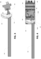
- FIG. 3 illustrates a visualization of an example off-axis aimer illuminator producing an aimer illumination in accordance with at least one example embodiment of the present disclosure.
- the off-axis aimer illuminator as illustrated includes an aimer light source 308 and an integrated illuminator-aimer lens 304 .
- the aimer light source 308 embodies a LED angled downwards in accordance with a particular axis (e.g., a first axis), such that the aimer light source 308 is oriented in alignment with particular optical component(s) of the integrated illuminator-aimer lens 304 , for example an integrated off-axis aimer projection lens 310 .
- the aimer light source 308 produces aimer light 306 .
- the integrated off-axis aimer projection lens 310 includes a light focusing lens and an axis redirecting lens.
- the light focusing lens receives aimer light 306 produced by the aimer light source 308 at an input face.
- the input face of the light focusing lens is similarly aligned at an angle to receive the aimer light 306 produced by the aimer light source 308 .
- the integrated off-axis aimer projection lens 310 refracts and/or otherwise manipulates the aimer light 306 .
- the integrated off-axis aimer projection lens 310 focuses and/or otherwise collimates the aimer light 306 .
- the integrated off-axis aimer projection lens 310 refracts the aimer light 306 to redirect the aimer light in a forward-facing direction (e.g., to the left of the illustrated image).
- the aimer light 306 is focused and refracted by such optics to project a corresponding aimer illumination 302 .
- the integrated off-axis aimer projection lens 310 projects the aimer illumination 302 at an output face, for example of an axis redirecting lens.
- the aimer illumination 302 is oriented in alignment with a different axis than the angled axis in which the aimer light source 308 is aligned.
- the aimer illumination 302 is projected along a forward-facing axis, for example normal to a field of view capturable by one or more corresponding imager(s).
- the aimer illumination 302 may be projected into the environment and onto a target object (e.g., to be imaged and scanned).
- FIG. 4 illustrates a visualization of an example off-axis aimer illuminator in an apparatus producing an aimer illumination in accordance with at least one example embodiment of the present disclosure.
- FIG. 4 illustrates the off-axis aimer illuminator depicted in FIG. 3 together with supporting circuitry 404 into a particular apparatus chassis 406 .
- the supporting circuitry 404 includes one or more printed circuit board(s), processor(s), interface(s), pin(s), and/or other hardware that communicatively couples with the aimer light source 308 to enable activation and/or deactivation of the aimer light source 308 .
- the aimer light 306 may only be generated upon receiving, via the supporting circuitry 308 , signal(s) that activate the aimer light source 308 .
- the supporting circuitry 404 may be communicatively coupled with other component(s) as well, for example one or more other light source(s) of illuminator(s), one or more image sensor(s) of imager(s), and/or the like.
- the supporting circuitry 404 includes a printed circuit board having the aimer light source 308 soldered or otherwise connected to said printed circuit board in a manner that enables transmission of data signals to and/or from the aimer light source 308 .
- the apparatus chassis 406 defines particular cavities for each component of the off-axis aimer illuminator, as well as the supporting circuitry 404 associated therewith.
- the apparatus chassis 406 includes defined cavities that fit and position the integrated illuminator-aimer lens 304 in front of the aimer light source 308 , and similarly positions the supporting circuitry 404 communicatively coupled to the aimer light source 308 .
- the apparatus chassis 406 includes one or more supporting arm(s) and/or other mechanism(s) that secure the components in place physically (e.g., via a pin, securing arm, screw, or other physical mean) or chemically (e.g., via a glue, bond, or other chemical mean).
- the apparatus chassis 406 is designed such that when the aimer light source 308 is secured, the aimer light source 308 is in alignment with the input face for the light focusing lens of the integrated off-axis aimer projection lens 310 .
- FIG. 4 depicts the integrated off-axis aimer projection lens 310 in a semi-transparent manner to further enable visualization of the light focusing and redirection performed by individual subcomponents thereof.
- the integrated off-axis aimer projection lens 310 includes a sub-portion embodying a light focusing lens 402 B, and a sub-portion embodying an axis redirecting lens 402 A.
- the light focusing lens 402 B includes an input face that receives the aimer light 306 from the aimer light source 308 and focuses the aimer light 306 for further manipulation.
- the light focusing lens 402 B does not have any output face, and the focused aimer light is immediately flows into internal optical components of the axis redirecting lens 302 A.
- the light focusing lens 402 B embodies a light collimator.
- the axis redirecting lens 402 A manipulates the orientation of the light focused or otherwise collimated via the light focusing lens 402 B to redirect the light towards a forward-facing direction.
- the axis redirecting lens 402 A includes one or more prism(s) that redirect the aimer light towards the forward-facing axis.
- the axis redirecting lens 402 A includes an output face via which the aimer illumination 302 is output.
- the output face is angled towards the forward-facing axis to similarly prevent the aimer illumination 302 or other light from reflecting back into the axis redirecting lens 402 A and towards the aimer light source 404 .
- the output face of the axis redirecting lens 402 A is flat.
- the flat output face embodies the optical element that functions to bend, refract, or otherwise redirect light in a particular direction.
- the output face may serve additional optical functions as well, whether flat or not flat.
- the output face embodies a cylindrical or other patternized front that converts light to a particular desired output pattern (e.g., a line, a speckle pattern, a cross, and/or the like).
- FIG. 5 A- 5 D each illustrate a different perspective view of an integrated illuminator-aimer lens for off-axis illumination projecting in accordance with at least one example embodiment of the present disclosure.
- FIGS. 5 A- 5 D depict an integrated illuminator-aimer lens 500 .
- the integrated illuminator-aimer lens 500 includes optical components for projecting illuminations of a plurality of field illuminators and an aimer illumination via an off-axis aimer.
- the integrated illuminator-aimer lens 500 is a specific example implementation of the integrated illuminator-aimer lens 304 .
- the integrated illuminator-aimer lens 500 is molded as a single piece, such that repositioning the integrated illuminator-aimer lens 500 repositions all subcomponents thereof.
- the integrated illuminator-aimer lens 500 includes a plurality of sub-component lenses permanently or temporarily affixed in position to one another.
- the integrated illuminator-lens 500 in some embodiments is constructed of glass, plastic, and/or another material that is transparent, mostly transparent, and/or the like.
- the integrated illuminator-aimer lens 500 includes a near-field illuminator lens 506 and a far-field illuminator lens 504 .
- the near-field illuminator lens 506 embodies a molded optical lens that receives near-field light from a near-field light source, and project a corresponding near-field illumination that illuminates a corresponding field of view.
- the near-field illuminator lens 506 may be designed in a manner that produces the near-field illumination of a particular pattern, length, width, and/or the like, at a particular intensity defined at least in part by the near-field light source.
- the far-field illuminator lens 504 embodies a molded optical lens that receives far-field light from a far-field light source, and project a corresponding far-field illumination that illuminates a corresponding field of view.
- each lens includes an input face that faces a corresponding light source and receives the light produced from the light source. Additionally or alternatively, in some embodiments, each lens includes an output face that faces the field of view into which the corresponding illumination is projected.
- the integrated illuminator-aimer lens 500 includes an integrated off-axis aimer projection lens that is used for off-axis aimer illumination projection.
- the integrated off-axis aimer projection lens includes a light focusing lens 508 and an axis redirecting lens 502 .
- the integrated off-axis aimer projection lens is positioned under the far-field illuminator lens 504 , and vertically central near (e.g., as close to centered between the two lenses vertically) the far-field illuminator lens 504 and near-field illuminator lens 506 .
- the aimer illumination projected via the integrated off-axis aimer projection lens may be minimized in distance from the center of the fields of view associated with the near-field illumination and far-field illumination.
- the light focusing lens 508 includes a lens face on the back of the integrated illuminator-aimer lens 500 .
- the lens face embodies an input face aligned at the same angle as a corresponding aimer light source, such that aimer light produced via the aimer light is produced towards and shines through the input face.
- the lens face may be angled upwards at a 15-degree angle in a circumstance where an aimer light, when positioned within an apparatus chassis, is angled downwards at a 15-degree angle.
- the lens face includes or is embodied by an aspherical lens, and/or the aimer light may be positioned to produce the aimer light towards a center of the aspherical lens.
- the axis redirecting lens 502 includes a lens face on the front of the integrated illuminator-aimer lens 500 .
- the axis redirecting lens 502 may be positioned lower than the corresponding light focusing lens 508 on the other side to provide sufficient volume for optical elements of the axis redirecting lens 508 and/or light focusing lens 502 to focus and/or redirect light to be in alignment with a particular axis.
- the lens face embodies an output face aligned with a targeted axis along which an aimer illumination is to be projected.
- the axis redirecting lens 502 extends outwards from a base portion of the integrated illuminator-aimer lens 500 , for example that connects the near-field illuminator lens, far-field lens, and integrated illuminator-aimer lens 500 into a single molded piece. Additionally or alternatively, in some embodiments as depicted, the axis redirecting lens 502 includes an angled face to reduce reflection from incoming light from reflecting back into the aimer light source. It will be appreciated that in other embodiments, the axis redirecting lens 502 need not include an angled face.
- one or more sub-lenses of the integrated illuminator-aimer lens 500 is designed based on one or more characteristics of a corresponding intended aimer light source.
- the light focusing lens 508 is designed with a particular curvature and/or conic constant based on the wavelength of aimer light produced by a desired aimer light source.
- a light focusing lens 508 designed for green light may be different than a light focusing lens 508 designed for red light or yellow light.
- the light focusing lens 508 includes a y-radius of 2.3 and a conic constant (k) of ⁇ 2.7910.
- the axis redirecting lens 502 is designed based on the one or more characteristics of a corresponding intended aimer light source. For example, in some embodiments, the axis redirecting lens 502 is designed based on an x, y, and/or z position value, and/or an x-offset (I), Y-offset (J), and/or Z-offset (K). Alternatively or additionally still, in some embodiments, the axis redirecting lens 502 is designed based on an alpha, beta, and/or gamma value. In one example embodiment, the off axis-projection lens 502 is designed based on an alpha value of ⁇ 12.00, with all remaining parameters set to 0.
- a front surface of the axis redirecting lens 502 is designed based on the corresponding aimer light source.
- the front surface embodying an output face is tilted at a particular angle based on the characteristics of the aimer light produced by a particular aimer light source.
- the output face is tilted at a 16.63 degree angle to refract aimer light of a particular configuration (e.g., green aimer light).
- a particular lens may be designed based on a combination of requirements for multiple aimer light source(s) (e.g., to enable use with a green light or a red light via the same lens).
- different parameters of different optical subcomponents may be configured to design a particular aimer sub-portion of an integrated illuminator-aimer lens 500 .
- FIG. 6 A illustrates an example assembly of an off-axis illuminator before assembly in accordance with at least one example embodiment of the present disclosure.
- FIG. 6 A depicts the integrated illuminator-aimer lens 500 together with supporting circuitry and related light sources for assembly.
- FIG. 6 B illustrates an example assembly of an off-axis illuminator as assembled in accordance with at least one example embodiment of the present disclosure.
- FIG. 6 B depicts the components of FIG. 6 A as assembled, such that the integrated illuminator-aimer lens 500 is fixedly attached the supporting circuitry at a position where the sub-lenses are properly positioned and oriented with respect to the corresponding light sources to form each of the illuminators.
- the integrated illuminator-aimer lens 500 may be secured to the front of the supporting circuitry 508 , as illustrated, to transition from the un-assembled components depicted in FIG. 6 A to the assembled components depicted in FIG. 6 B .
- the off-axis illuminator assembly includes supporting circuitry 608 that embodies a flexible printed circuit board.
- the flexible printed circuit board includes multiple layers, which may be rigid or flexible as well, with connective circuitry between such layers that enables transmission of signals to and/or from components communicatively coupled at each layer.
- the front layer of the supporting circuitry 608 includes a near-field light source 604 and a far-field light source 606 . It will be appreciated that the far-field light source 606 and near-field light source 604 may be soldered, pinned, or otherwise fixedly connected to the supporting circuitry 608 in a manner that communicatively couples such components with the supporting circuitry 608 .
- Each of the individual light sources are aligned with a particular sub-lens of the integrated illuminator-aimer lens 500 .
- the near-field light source 604 is positioned behind and aligned with the near-field illuminator lens 506 as depicted and described herein to enable projection of a near-field illumination from near-field light produced by the near-field light source 604 .
- the near-field light source 604 shines light through the near-field illuminator lens 506 to produce a specific near-field illumination based on the design of the near-field illuminator lens 506 .
- the far-field light source 606 is positioned behind and aligned with the far-field illuminator lens 504 as depicted and described herein to enable projection of a far-field illumination from far-field light produced by the far-field light source 606 .
- the far-field light source 606 shines light through the far-field illuminator lens 504 to produce a specific far-field illumination based on the design of the far-field illuminator lens 504 .
- the supporting circuitry 608 further includes a second layer, which is positioned behind the first layer including the far-field light source 606 and the near-field light source 604 .
- the second layer of the supporting circuitry 608 is communicatively coupled with an aimer light source 602 .
- the aimer light source 602 may be soldered, pinned, or otherwise fixedly connected to the supporting circuitry 608 in a manner that communicatively couples the aimer light source 602 with the supporting circuitry 608 .
- the aimer light source 602 is larger (and may be significantly larger, such as by an order of magnitude or more) than either or both of the near-field light source 604 and/or the far-field light source 606 .
- Such size difference may exist for any of a myriad of reasons.
- the aimer light source 602 embodies a light source that produces light of a particular color (e.g., green or red, or any other color) whereas the far-field light source 606 and/or the near-field light source 604 may embody a light source that produces white light.
- the color light may require electrical components of a larger size, more electrical components, optical components within the aimer light source 602 , and/or the like.
- the aimer light 602 is of a greater power level than the power level than the near-field light source 604 and/or the far-field light source 606 , where such an increased power level requires larger electrical components. It will be appreciated that, regardless of such reasons, the aimer light source 602 may ideally be positioned in a manner that enables projection of the aimer illumination pattern as centrally to the one or more capturable fields of view while simultaneously enabling the other light sources to produce illuminations intended to illuminate the capturable light sources with different intensities of light, for example to enable imaging.
- the first layer includes a cutout between the far-field light source 606 and the near-field light source 604 .
- the cutout portion may be positioned in front of the aimer light source 602 to prevent any circuitry from blocking the aimer light produced via the aimer light source 602 .
- the cutout portion allows the aimer light source 602 to be positioned in a manner that aligns the produced light relatively centrally to the near-field light source 604 and the far-field light source 606 .
- the aimer light source 602 similarly is angled downwards.
- the aimer light source 602 may be angled downwards such that it is aligned with a particular sub-lens of the integrated illuminator-aimer lens 500 , such as the light focusing lens 508 embodied as an input face on the back of the integrated off-axis aimer projection lens 500 .
- the aimer light source 602 produces aimer light that shines through and manipulated via the light focusing lens 508 and axis redirecting lens 502 to be projected as a particular desired aimer illumination.
- the aimer illumination may be configured based on the particular design of the light focusing lens 508 and/or axis redirecting lens 502 , for example to produce a particular intensity level, pattern, and/or the like.
- FIG. 7 illustrates an exploded view of an example off-axis aimer apparatus in accordance with at least one example embodiment of the present disclosure.
- FIG. 7 illustrates an exploded view of a particular off-axis aimer apparatus 700 embodying a multi-imager and multi-illuminator off-axis aimer.
- the off-axis aimer apparatus 700 is configured to produce two different field illuminations, capture two different fields of view, and generate an aimer illumination within said fields of view via an off-axis aimer illuminator arrangement as described herein.
- the off-axis aimer apparatus 700 may include imaging and/or illuminator components that are each oriented in alignment with a particular forward-facing directional axis, for example defining the direction of a center for the capturable fields of view and/or produced illuminations.
- the off-axis aimer apparatus 700 includes an integrated illuminator-aimer lens 702 .
- the integrated illuminator-aimer lens 702 is embodied by the integrated illuminator-aimer lens 500 as depicted and described herein.
- the integrated illuminator-aimer lens 702 is embodied having a light focusing lens including an input face aligned with an aimer light source at a different angle than the integrated illuminator-aimer lens 500 .
- the off-axis aimer apparatus 700 instead includes a plurality of individual lenses not integrated into a single piece.
- the off-axis aimer apparatus 700 may include a separate near-field illuminator lens, far-field illuminator lens, and integrated off-axis aimer projection lens. Additionally or alternatively still, in some embodiments, the off-axis aimer apparatus 700 includes a separate light focusing lens and axis redirecting lens rather than an integrated off-axis aimer projection lens.
- the off-axis aimer apparatus 700 includes the integrated illuminator-aimer lens 702 that is positioned between a near-field lens 704 A and a far-field lens 704 B.
- the near-field lens 704 A includes one or more optical component(s) that define a capturable near field of view.
- the far-field lens 704 B includes one or more optical component(s) that define a capturable far field of view.
- the near-field lens 704 A and far-field lens 704 B each include one or more optical lenses that are defined at different focal lengths.
- the focal length of the far-field lens 704 B may be associated with a focal length that is greater than the focal length associated with the near-field lens.
- the far-field lens 704 B further defines a narrower field of view than the near-field lens 704 A, for example with greater clarity within that field of view at a greater distance in accordance with the greater focal length.
- the off-axis aimer apparatus 700 further includes an assembly of illuminator and imagery hardware.
- the off-axis aimer apparatus 700 includes supporting circuitry 710 communicative couplable to a near-field image sensor 712 A, a far-field image sensor 712 B, a near-field light source 714 A, a far-field light source 714 B, and/or an aimer light source 708 .
- the supporting circuitry 710 embodies a printed circuit board, integrated circuitry, and/or other wiring that enables transmission of electrical and/or data signals to and/or from the components communicatively coupled therewith.
- the supporting circuitry 710 is communicatively coupled with the near-field light source 714 A, far-field light source 714 B, and/or aimer light source 708 to enable signal(s) to be transmitted to such components that trigger activation and/or deactivation of the component(s) individually, for example to enable any such component to begin producing light and/or stop any such component from producing light.
- the supporting circuitry 710 is communicatively coupled with the far-field image sensor 712 B and the near-field image sensor 712 A to enable signal(s) to be transmitted to such components that trigger activation and/or deactivation of the component(s) individually, and/or output of corresponding data from such component(s).
- either of the image sensors may be activated to trigger the image sensor to capture data embodying a representation of an environment, and the resulting image data object captured via the image sensor is output from the sensor via the supporting circuitry 710 for transmission to and/or processing via another component (e.g., a processor communicatively coupled via the supporting circuitry 710 ).
- another component e.g., a processor communicatively coupled via the supporting circuitry 710 .
- the near-field image sensor 712 A and the far-field image sensor 712 B each embodies an electrical component configured for capturing images from light impacting such electrical components (e.g., light incident on the image sensor).
- image sensor(s) include a CMOS sensor and/or a CCD sensor.
- the near-field image sensor 712 A is associated with a different resolution than the far-field image sensor 712 B.
- the far-field image sensor 712 B and the near-field image sensor 712 A are configured in accordance with the same resolution.
- the off-axis aimer apparatus 700 further includes a component holder 706 .
- the component holder 706 includes defined cavities that position and align various components of the off-axis aimer apparatus 700 .
- the component holder 706 includes cavities for receiving the near-field lens 704 A, the far-field lens 704 B, and the integrated illuminator-aimer lens 702 .
- the component holder 706 includes one or more snaps, grooves, arms, or other physical components that secure the components into a particular position and/or alignment, for example to prevent movement and/or rotation of such components separate from movement and/or rotation of other corresponding components of the off-axis aimer apparatus 700 .
- each of the supporting circuitry 710 and the components communicatively coupled therewith are positioned and aligned via the component holder 706 in alignment with the corresponding lenses similarly positioned and aligned via the component holder 706 .
- the far-field image sensor 712 B affixed to the supporting circuitry 710 may be positioned within a cavity of the component holder 706 in alignment with the far-field lens 704 B similarly positioned within a cavity of the component holder 706 , thereby forming a far-field imager defining a particular capturable far field of view.
- the near-field image sensor 712 B affixed to the supporting circuitry 710 may be positioned within a cavity of the component holder 706 in alignment with the near-field lens 704 A similarly positioned within a cavity of the component holder 706 , thereby forming a near-field imager defining a particular capturable near field of view.
- the near field of view may be broader than the far field of view, such that the far field of view represents a sub-view of the near field of view.
- the far field imager captures clearer images when an object is further from the off-axis aimer apparatus 700
- the near field imager captures clearer images when an object is closer to the off-axis aimer apparatus 700 , for example based on the different focal ranges associated with each imager.
- the near-field light source 714 A is similarly positioned within a cavity of the component holder 706 in alignment with a particular sub-lens of the integrated illuminator-aimer lens 702 , for example the corresponding near-field illumination lens thereof.
- the far-field light source 714 B is similarly positioned within a cavity of the component holder 706 in alignment with another sub-lens of the integrated illuminator-aimer lens 702 , for example the corresponding far-field illumination lens thereof.
- such components define a far-field illuminator that generates a particular far field illumination, and a near-field illuminator that generates a particular near field illumination.
- the far field illumination may be more concentrated than the near field illuminator, enabling the far field illumination to better illuminate objects at a further distance corresponding to the further focal length of a corresponding far-field imager.
- the aimer light source 708 affixed to the supporting circuitry 710 is similarly positioned within a cavity of the component holder 706 in alignment with a particular sub-lens of the integrated illuminator-aimer lens 702 , for example at least an input face of a corresponding light focusing lens thereof.
- the component holder 706 may define the cavity in a manner that secures the aimer light 708 at a particular angle (e.g., downwards at the particular angle) that differs from the forward-facing directional axis of the other components in the off-axis aimer apparatus 700 .
- the light produced by the aimer light source 708 may shine uninterrupted until it reaches the sub-lens of the integrated illuminator-aimer lens 702 , for example an input face of a light focusing lens, and subsequently be manipulated for focusing and/or redirection into alignment with the forward-facing directional axis.
- the vertical profile (e.g., embodying the height) of the off-axis aimer apparatus 700 may be reduced.
- the aimer light 708 is associated with a particular diameter, thereby limiting the particular dimensions of the off-axis aimer apparatus 700 .
- all dimensions of the off-axis aimer apparatus 700 would be limited to the diameter of the aimer light 708 , particularly a height dimension that often is the smallest dimension.
- angling the aimer light 708 further provides the advantage of enabling smaller form factor apparatuses, such that the off-axis aimer apparatus 700 may be utilized in mobile and/or other small form factor use cases.
- the off-axis aimer apparatus 700 includes an apparatus height of under 6.8 millimeters, for example enabling the apparatus to be implemented along edges of small form factor mobile devices and/or the like. Additionally or alternatively, in some embodiments the apparatus 700 embodies an apparatus width of 23.5 millimeters and a depth of 16.2 millimeters.
- FIGS. 8 A- 8 D each illustrate a different views of an assembled example off-axis aimer apparatus in accordance with at least one example embodiment of the present disclosure.
- FIG. 8 A depicts a front angled perspective view of the off-axis aimer apparatus 800 comprising the off-axis aimer apparatus 700 when fully assembled
- FIG. 8 B depicts a back angled perspective view of the off-axis aimer apparatus 800 comprising the off-axis aimer apparatus 700 when fully assembled
- FIG. 8 C depicts a top-down view of the off-axis aimer apparatus 800 comprising the off-axis aimer apparatus 700 when fully assembled
- FIG. 8 A depicts a front angled perspective view of the off-axis aimer apparatus 800 comprising the off-axis aimer apparatus 700 when fully assembled
- FIG. 8 B depicts a back angled perspective view of the off-axis aimer apparatus 800 comprising the off-axis aimer apparatus 700 when fully assembled
- FIG. 8 C depicts a top-down view of the off-axis aim
- FIG. 8 D depicts a front orthographic view of the off-axis aimer apparatus 800 comprising the off-axis aimer apparatus 700 when fully assembled.
- the components as depicted and described with respect to FIG. 7 are each positioned and aligned within the component holder.
- FIGS. 8 A- 8 D depict example engine input/output circuitry 802 .
- the engine input/output circuitry 802 embodies a multi-pinned interface that enables connection to the supporting circuitry of the off-axis aimer apparatus 800 .
- the engine input/output circuitry 802 enables the electrical and/or data signal transmission to and/or from the components of the off-axis aimer apparatus 800 , and to and/or from an external processor, device, and/or the like.
- the engine input/output circuitry 802 is usable to connect the off-axis aimer apparatus 800 with at least one processor and/or memory of a scanning device, enabling the at least one processor and/or memory to transmit signal(s) that activate component(s) of the off-axis aimer apparatus 800 and/or transmit signal(s) that retrieve image data captured via the component(s) thereof.
- the engine input/output circuitry 802 receives a cable of any known electrical wiring standard that connects the off-axis aimer apparatus 800 to such an external device and/or component(s). It should be appreciated that the engine input/output circuitry 802 in some embodiments enables the off-axis aimer apparatus 800 to be utilized modularly within different, larger apparatus chasses for use in different imaging use cases.
- the components of the off-axis aimer apparatus 800 are affixed within a particular apparatus chassis utilizing any of a myriad of manners and/or mechanisms.
- the components of the off-axis aimer apparatus 800 are affixed within an apparatus chassis utilizing one or more fitting mechanism(s), including and without limitation one or more slot(s), pin(s), hole(s), and/or the like.
- the components of the off-axis aimer apparatus 800 are affixed within an apparatus chassis utilizing adhesive and/or other chemical mechanism(s).
- FIGS. 9 A- 9 C each illustrate a different view of an example aimer illumination projected by an example off-axis aimer apparatus in accordance with at least one example embodiment of the present disclosure.
- FIGS. 9 A- 9 C each illustrate projection of an example aimer illumination 902 in alignment with a forward-facing axis 950 via an off-axis aimer illuminator.
- FIGS. 9 B and 9 C illustrates such projection in a wireframed manner that depicts the manipulation of the light to project said aimer illumination.
- the forward-facing axis 950 is defined by the capturable fields of view.
- the off-axis aimer apparatus includes the near-field imager and the far-field imager, with the forward-facing axis 950 defined by a central point of the lens and image sensor of said imagers.
- the central point may similarly define a central point of the fields of view capturable via the apparatus.
- aimer light 906 is produced at a particular angle based on the angle of the corresponding aimer light source that produces said aimer light 906 .
- the aimer light 906 may be produced in alignment with the downward-facing axis 952 .
- the downward-facing axis 952 may be defined based on the angle of the aimer light source.
- the downward-facing axis 952 is aligned with the corresponding forward-facing axis 950 in one or more other dimensions.
- the aimer light 906 is produced into a light focusing lens, for example of an integrated off-axis aimer projection lens.
- the aimer light 906 then enters the optical components of the light focusing lens and is manipulated via the light focusing lens and/or an associated axis redirecting lens.
- the aimer light 906 that enters the integrated off-axis aimer projection lens (“intra-lens light 904 ”) is manipulated by the optical components to focus and/or redirect the light.
- the intra-lens light 904 is first be focused and/or collimated via the light focusing lens.
- the resulting collimated or focused light is refracted, for example by an axis redirecting lens, to redirect the intra-lens light 904 from the downward-facing axis 952 to the forward-facing axis 950 .
- the axis redirecting lens may include one or more prism(s) or other optical components that facilitates such refraction at a defined angle.
- the axis redirecting lens embodies a flat surface that functions as the prism.
- the axis redirecting lens may refract the intra-lens light 904 in a manner that avoids refraction in any dimension that is not already in alignment with the forward-facing axis 950 .
- the light resulting after redirection is projected as the aimer illumination 902 .
- further manipulation of the light is not necessary.
- the aimer illumination 902 is projected into the environment to be viewed by a user, for example a user utilizing the device for scanning of machine-readable code(s).
- example properties of example aimer patterns in accordance with the present disclosure will now be discussed.
- Some of the aimer patterns as depicted and described in FIG. may be projected via the example apparatuses, components, and/or subassemblies discussed herein, for example using the off-axis aimer arrangements described herein. Additionally, some of the aimer patterns as depicted and described in FIG. 10 are projected via on-axis aimer arrangements for comparison with the off-axis aimer arrangement described herein.
- FIG. 10 illustrates intensity levels of different aimer illuminations projected by on-axis aimers and different off-axis aimers in accordance with at least one example embodiment of the present disclosure.
- FIG. 10 depicts a plurality of intensity level graphs for green off-axis aimer illuminations projected using an off-axis aimer illuminator arrangement—graphs 1002 A, 1002 B, 1002 C, and 1002 D—a plurality of intensity level graphs for red off-axis aimer illuminations projected using an off-axis aimer illuminator arrangement—graphs 1004 A, 1004 B, 1004 C, and 1004 D—and a plurality of intensity level graphs for red on-axis illumination projected using a conventional on-axis aimer illuminator arrangement—graphs 1006 A, 1006 B, 1006 C, and 1006 D.
- Each of the graphs depicted represents an intensity level of an aimer illumination at one of a plurality of distances, specifically 0.1 meter from a target, 1 meter from a target, 2.5 meters from a target, and 10 meters from a target.
- the graphs represent captured data from testing the different on-axis and off-axis illuminator arrangements with respective colors.
- Each graph is associated with a particular intensity, for example having a unit of mJ/mm 2 .
- an intensity value of 4.2 represents 4.2 millijoule per square millimeter.
- each graph is associated with a particular efficiency value, where the efficiency value represents a ratio of output power of the aimer illumination to source power of the aimer light produced via the aimer light source(s). For example, an efficiency value of 0.68 represents that 68% of the aimer light produced via the aimer light source(s) will be projected as an aimer illumination.
- graphs corresponding to the 0.1 meter distance from the target each indicate aimer illuminations having intensity levels that would appear bright to a human user.
- graph 1002 A corresponds to a green off-axis aimer illumination having a peak intensity of 4.2 and an efficiency of 0.68, together with an x-radius of 0.55 millimeters and a y-radius of 1.1 millimeters
- graph 1004 A corresponds to a red off-axis aimer illumination having a peak intensity of 5.8 and an efficiency of 0.69, together with an x-radius of 0.4 millimeters and a y-radius of 1.0 millimeters.
- the graph 1006 A corresponds to a red on-axis aimer illumination having a peak intensity of 5.4 and an efficiency of 0.53, together with an x-radius of 0.42 millimeters and a y-radius of 0.90 millimeters.
- any of the arrangements create an aimer illumination of sufficient size, intensity, and efficiency to be practically implemented and visible to a human operator.
- graphs corresponding to the 1 meter distance from the target each indicate aimer illuminations having intensity levels that would appear bright to a human user.
- graph 1002 B corresponds to a green off-axis aimer illumination having a peak intensity of 5.8 and an efficiency of 0.68, together with an x-radius of 0.55 millimeters and a y-radius of 0.66 millimeters.
- graph 1004 B corresponds to a red off-axis aimer illumination having a peak intensity of 7.7 and an efficiency of 0.69, together with an x-radius of millimeters and a y-radius of 0.44 millimeters.
- graph 1004 C corresponds to a red on-axis aimer illumination having a peak intensity of 6.4 and an efficiency of 0.53, together with an x-radius of 0.43 millimeters and a y-radius of 0.6 millimeters.
- all such arrangements would create an aimer illumination of sufficient size, intensity, and efficiency to be practically implemented and visible to a human operator.
- graph 1006 C corresponds to a red on-axis aimer illumination having a peak intensity of 1.1 and an efficiency of 0.5, together with an x-radius of 1.4 millimeters and a y-radius of 1.0 millimeters.
- the intensity of this aimer illumination remains somewhat visible to a human operator, but likely will be difficult to see, especially under particular ambient lighting conditions (e.g., under direct sunlight). For example, light may become not visible under the 1 mJ/mm 2 threshold in direct sunlight ambient light.
- graph 1002 C corresponds to a green off-axis aimer illumination having a peak intensity of 3.7 and an efficiency of 0.66, together with an x-radius of 0.83 millimeters and a y-radius of 0.65 millimeters.
- graph 1004 C corresponds to a red off-axis aimer illumination having a peak intensity of 2.2 and an efficiency of 0.67, together with an x-radius of 1.2 millimeters and a y-radius of 0.8 millimeters.
- the intensities of the green and red off-axis aimer illuminations are significantly brighter (e.g., 2 ⁇ or 3 ⁇ in intensity), such that the aimer illuminations are well-defined and remain sufficiently visible to the user at these longer ranges.
- graph 1006 D corresponds to a red on-axis aimer illumination having a peak intensity of 0.07 and an efficiency of 0.52, together with an x-radius of 5.7 millimeters and a y-radius of 4.1 millimeters.
- the intensity of this aimer illumination would likely be difficult if not impossible for most human operators to see.
- graph 1002 D corresponds to a green off-axis aimer illumination having a peak intensity of 0.26 and an efficiency of 0.67, together with an x-radius of 4.3 millimeters and a y-radius of 3.2 millimeters.
- graph 1004 D corresponds to a red off-axis aimer illumination having a peak intensity of 0.13 and an efficiency of 0.68, together with an x-radius of 4.6 millimeters and a y-radius of 3.2 millimeters.
- the intensities of the green and red off-axis aimer illuminations are significantly brighter (e.g., almost 4 ⁇ as bright) than the corresponding on-axis aimer illumination.
- the different color aimer illuminations can be perceived differently by a human user.
- the intensity differences may further be exacerbated with respect to a human operator's perception of the aimer illuminations in a circumstance where green light is utilized instead of red light.
- the green light may be significantly more perceptible to a human operator, such that a green off-axis aimer illuminator, for example, is ⁇ 7 ⁇ more perceptible to a human operator than a corresponding red on-axis aimer illuminator.
- the color of the aimer light further enhances such improvements.
- certain color light sources embody larger components.
- green aimer light sources often are larger than red aimer light sources of the same intensity.
- the off-axis aimer arrangement described herein may nevertheless fit within small frame apparatus.
- conventional on-axis aimer arrangements may not be capable of fitting such colored aimer light sources (e.g., in implementations having a height of under 6.8 mm, or at or under 7 millimeters)
- the off-axis aimer arrangements described herein may fit such colored aimer light sources and provide improved visibility to a human operator simultaneously.
- the off-axis aimer arrangements described herein enable small form factor imaging engines that are capable of fitting in smaller form factor apparatuses, for example having smaller height dimensions, than existing aimer arrangements.
- each of the flowcharts depicts an example processes that may be performed by one or more components of the above described apparatuses, for example any of the apparatuses depicted and/or described in FIGS. 1 - 9 .
- the blocked operations of each process may be arranged in any of a number of ways, as depicted and described herein.
- one or more operations of a first process may occur in-between one or more operations, or otherwise operate as a sub-process, of a second process.
- the process may include some or all of the steps described and/or depicted, including one or more optional operations in some embodiments.
- one or more of the depicted operations may be optional in some, or all, embodiments of the present disclosure.
- Optional operations are depicted with broken (or “dashed”) lines.
- one or more of the operations of each flowcharts may be combinable, replaceable, and/or otherwise altered as described herein.
- FIG. 11 illustrates an example process 1100 for using an off-axis aimer arrangement, in accordance with at least one example embodiment of the present disclosure.
- the example process 1100 may be performed by one or more specially configured apparatuses, such as the off-axis aimer imaging apparatus 200 .
- the off-axis aimer imaging apparatus 200 may be configured to perform one or more of the operations described herein utilizing one or more of the components therein, such as the processor 202 , memory 204 , and/or off-axis aimer imaging engine 100 .
- the off-axis aimer imaging apparatus 200 is configured for performing one or more of the operations as depicted and described by executing computer program instructions stored therein, for example in the memory 204 .
- the process 1100 begins at operation 1102 .
- the process 1100 generates, via an aimer light source, aimer light oriented in alignment with a light focusing lens.
- the aimer light source is oriented along a first axis, for example where the aimer light source embodies an off-axis aimer light source angled at a particular angle with respect to a different second axis (e.g., a forward-facing axis).
- a processor activates the aimer light source to generate the corresponding aimer light.
- the process 1100 projects, via the light focusing lens to an axis redirecting lens, focused light from the aimer light.
- the light focusing lens includes an input face that receives the aimer light generated by the aimer light source, and similarly the axis redirecting lens includes an output face.
- the light focusing lens and the axis redirecting lens are integrated or otherwise molded into a single piece, forming an integrated off-axis aimer projection lens.
- light may be manipulated throughout optical components of the light focusing lens and the axis redirecting lens directly through the single piece.
- the light focusing lens and the axis redirecting lens are embodied by separate lenses, where an output face of the light focusing lens is aligned with an input face of the axis redirecting lens.
- the process 1100 projects, via an output face of the axis redirecting lens, an aimer illumination oriented along a second axis that differs from the first axis.
- the second axis embodies a forward-facing axis associated with the off-axis aimer imaging apparatus 200 .
- the output face may embody an angled face that refracts the focused light and outputs the aimer illumination in alignment with the second axis.
- the output face of the axis redirecting lens may project the aimer illumination on-axis with the second axis.
- the aimer illumination may be projected into one or more field(s) of view capturable by the off-axis aimer imaging apparatus 200 .
- some of the operations above may be modified or further amplified. Furthermore, in some embodiments, additional optional operations may be included. Modifications, amplifications, or additions to the operations above may be performed in any order and in any combination.
- Embodiments of the subject matter and the operations described herein can be implemented in digital electronic circuitry, or in computer software, firmware, or hardware, including the structures disclosed in this specification and their structural equivalents, or in combinations of one or more of them.
- Embodiments of the subject matter described herein can be implemented as one or more computer programs, i.e., one or more modules of computer program instructions, encoded on computer storage medium for execution by, or to control the operation of, information/data processing apparatus.
- the program instructions can be encoded on an artificially-generated propagated signal, e.g., a machine-generated electrical, optical, or electromagnetic signal, which is generated to encode information/data for transmission to suitable receiver apparatus for execution by an information/data processing apparatus.
- a computer storage medium can be, or be included in, a computer-readable storage device, a computer-readable storage substrate, a random or serial access memory array or device, or a combination of one or more of them.
- a computer storage medium is not a propagated signal, a computer storage medium can be a source or destination of computer program instructions encoded in an artificially-generated propagated signal.
- the computer storage medium can also be, or be included in, one or more separate physical components or media (e.g., multiple CDs, disks, or other storage devices).
- the operations described herein can be implemented as operations performed by an information/data processing apparatus on information/data stored on one or more computer-readable storage devices or received from other sources.
- the term “data processing apparatus” encompasses all kinds of apparatus, devices, and machines for processing data, including by way of example a programmable processor, a computer, a system on a chip, or multiple ones, or combinations, of the foregoing.
- the apparatus can include special purpose logic circuitry, e.g., an FPGA (field programmable gate array) or an ASIC (application-specific integrated circuit).
- the apparatus can also include, in addition to hardware, code that creates an execution environment for the computer program in question, e.g., code that constitutes processor firmware, a protocol stack, a repository management system, an operating system, a cross-platform runtime environment, a virtual machine, or a combination of one or more of them.
- the apparatus and execution environment can realize various different computing model infrastructures, such as web services, distributed computing and grid computing infrastructures.
- a computer program (also known as a program, software, software application, script, or code) can be written in any form of programming language, including compiled or interpreted languages, declarative or procedural languages, and it can be deployed in any form, including as a stand-alone program or as a module, component, subroutine, object, or other unit suitable for use in a computing environment.
- a computer program may, but need not, correspond to a file in a file system.
- a program can be stored in a portion of a file that holds other programs or information/data (e.g., one or more scripts stored in a markup language document), in a single file dedicated to the program in question, or in multiple coordinated files (e.g., files that store one or more modules, sub-programs, or portions of code).
- a computer program can be deployed to be executed on one computer or on multiple computers that are located at one site or distributed across multiple sites and interconnected by a communication network.
- processors suitable for the execution of a computer program include, by way of example, both general and special purpose microprocessors, and any one or more processors of any kind of digital computer.
- a processor will receive instructions and information/data from a read-only memory or a random access memory or both.
- the essential elements of a computer are a processor for performing actions in accordance with instructions and one or more memory devices for storing instructions and data.
- a computer will also include, or be operatively coupled to receive information/data from or transfer information/data to, or both, one or more mass storage devices for storing data, e.g., magnetic, magneto-optical disks, or optical disks.
- mass storage devices for storing data
- a computer need not have such devices.
- Devices suitable for storing computer program instructions and information/data include all forms of non-volatile memory, media and memory devices, including by way of example semiconductor memory devices, e.g., EPROM, EEPROM, and flash memory devices; magnetic disks, e.g., internal hard disks or removable disks; magneto-optical disks; and CD-ROM and DVD-ROM disks.
- the processor and the memory can be supplemented by, or incorporated in, special purpose logic circuitry.
- a computer having a display device, e.g., a CRT (cathode ray tube) or LCD (liquid crystal display) monitor, for displaying information/data to the user and a keyboard and a pointing device, e.g., a mouse or a trackball, by which the user can provide input to the computer.
- a display device e.g., a CRT (cathode ray tube) or LCD (liquid crystal display) monitor
- a keyboard and a pointing device e.g., a mouse or a trackball
- Other kinds of devices can be used to provide for interaction with a user as well; for example, feedback provided to the user can be any form of sensory feedback, e.g., visual feedback, auditory feedback, or tactile feedback; and input from the user can be received in any form, including acoustic, speech, or tactile input.
- a computer can interact with a user by sending documents to and receiving documents from a device that is used by the user; for example, by sending web
- Embodiments of the subject matter described herein can be implemented in a computing system that includes a back-end component, e.g., as an information/data server, or that includes a middleware component, e.g., an application server, or that includes a front-end component, e.g., a client computer having a graphical user interface or a web browser through which a user can interact with an implementation of the subject matter described herein, or any combination of one or more such back-end, middleware, or front-end components.
- the components of the system can be interconnected by any form or medium of digital information/data communication, e.g., a communication network.
- Examples of communication networks include a local area network (“LAN”) and a wide area network (“WAN”), an inter-network (e.g., the Internet), and peer-to-peer networks (e.g., ad hoc peer-to-peer networks).
- LAN local area network
- WAN wide area network
- inter-network e.g., the Internet
- peer-to-peer networks e.g., ad hoc peer-to-peer networks.
- the computing system can include clients and servers.
- a client and server are generally remote from each other and typically interact through a communication network. The relationship of client and server arises by virtue of computer programs running on the respective computers and having a client-server relationship to each other.
- a server transmits information/data (e.g., an HTML page) to a client device (e.g., for purposes of displaying information/data to and receiving user input from a user interacting with the client device).
- Information/data generated at the client device e.g., a result of the user interaction
Landscapes
- Engineering & Computer Science (AREA)
- Physics & Mathematics (AREA)
- Signal Processing (AREA)
- Multimedia (AREA)
- General Physics & Mathematics (AREA)
- Theoretical Computer Science (AREA)
- Electromagnetism (AREA)
- Computing Systems (AREA)
- Human Computer Interaction (AREA)
- Toxicology (AREA)
- Artificial Intelligence (AREA)
- Computer Vision & Pattern Recognition (AREA)
- General Health & Medical Sciences (AREA)
- Health & Medical Sciences (AREA)
- Optics & Photonics (AREA)
- Non-Portable Lighting Devices Or Systems Thereof (AREA)
Abstract
Description
Claims (20)
Priority Applications (3)
| Application Number | Priority Date | Filing Date | Title |
|---|---|---|---|
| US17/808,241 US12200375B2 (en) | 2022-06-22 | 2022-06-22 | Apparatuses, computer-implemented methods, and computer program products for off-axis illumination projection and use |
| EP23175026.6A EP4296885B1 (en) | 2022-06-22 | 2023-05-24 | Apparatuses for off-axis illumination projection |
| CN202310660871.5A CN117270297A (en) | 2022-06-22 | 2023-06-06 | Apparatus, computer-implemented method and computer program product for off-axis illumination projection and uses |
Applications Claiming Priority (1)
| Application Number | Priority Date | Filing Date | Title |
|---|---|---|---|
| US17/808,241 US12200375B2 (en) | 2022-06-22 | 2022-06-22 | Apparatuses, computer-implemented methods, and computer program products for off-axis illumination projection and use |
Publications (2)
| Publication Number | Publication Date |
|---|---|
| US20230421918A1 US20230421918A1 (en) | 2023-12-28 |
| US12200375B2 true US12200375B2 (en) | 2025-01-14 |
Family
ID=86603765
Family Applications (1)
| Application Number | Title | Priority Date | Filing Date |
|---|---|---|---|
| US17/808,241 Active 2042-06-24 US12200375B2 (en) | 2022-06-22 | 2022-06-22 | Apparatuses, computer-implemented methods, and computer program products for off-axis illumination projection and use |
Country Status (3)
| Country | Link |
|---|---|
| US (1) | US12200375B2 (en) |
| EP (1) | EP4296885B1 (en) |
| CN (1) | CN117270297A (en) |
Families Citing this family (2)
| Publication number | Priority date | Publication date | Assignee | Title |
|---|---|---|---|---|
| CN109141289B (en) * | 2018-08-01 | 2020-12-29 | 先临三维科技股份有限公司 | Three-dimensional scanning method and system |
| GB2621765A (en) * | 2021-05-28 | 2024-02-21 | Zebra Tech Corp | Imaging lens system and scan engine chassis |
Citations (7)
| Publication number | Priority date | Publication date | Assignee | Title |
|---|---|---|---|---|
| JP3486804B2 (en) * | 1998-03-30 | 2004-01-13 | 富士写真光機株式会社 | Tip structure of insertion section for oblique endoscope |
| US20050284942A1 (en) | 2004-06-29 | 2005-12-29 | Vladimir Gurevich | Aiming light pattern generator in imaging readers for electro-optically reading indicia |
| US7841750B2 (en) | 2008-08-01 | 2010-11-30 | Ruud Lighting, Inc. | Light-directing lensing member with improved angled light distribution |
| US9885458B2 (en) | 2010-01-25 | 2018-02-06 | Light Prescription Innovators, Llc | Off-axis collimation optics |
| US11009786B1 (en) * | 2019-11-14 | 2021-05-18 | Hand Held Products, Inc. | Integrated illumination-aimer imaging apparatuses |
| US11036944B1 (en) * | 2020-02-04 | 2021-06-15 | Hand Held Products, Inc. | Alternative illuminator assembly and mobile imaging apparatus for improved direct part marking reading |
| US20220100979A1 (en) * | 2020-09-28 | 2022-03-31 | Cognex Corporation | Machine vision system and method with on-axis aimer and distance measurement assembly |
-
2022
- 2022-06-22 US US17/808,241 patent/US12200375B2/en active Active
-
2023
- 2023-05-24 EP EP23175026.6A patent/EP4296885B1/en active Active
- 2023-06-06 CN CN202310660871.5A patent/CN117270297A/en active Pending
Patent Citations (9)
| Publication number | Priority date | Publication date | Assignee | Title |
|---|---|---|---|---|
| JP3486804B2 (en) * | 1998-03-30 | 2004-01-13 | 富士写真光機株式会社 | Tip structure of insertion section for oblique endoscope |
| US20050284942A1 (en) | 2004-06-29 | 2005-12-29 | Vladimir Gurevich | Aiming light pattern generator in imaging readers for electro-optically reading indicia |
| EP1776653B1 (en) | 2004-06-29 | 2012-08-01 | Symbol Technologies, Inc. | Aiming light pattern generator in imaging readers for electro-optically reading indicia |
| US7841750B2 (en) | 2008-08-01 | 2010-11-30 | Ruud Lighting, Inc. | Light-directing lensing member with improved angled light distribution |
| US9885458B2 (en) | 2010-01-25 | 2018-02-06 | Light Prescription Innovators, Llc | Off-axis collimation optics |
| US11009786B1 (en) * | 2019-11-14 | 2021-05-18 | Hand Held Products, Inc. | Integrated illumination-aimer imaging apparatuses |
| EP3822702A1 (en) | 2019-11-14 | 2021-05-19 | Hand Held Products, Inc. | Integrated illumination-aimer imaging apparatuses |
| US11036944B1 (en) * | 2020-02-04 | 2021-06-15 | Hand Held Products, Inc. | Alternative illuminator assembly and mobile imaging apparatus for improved direct part marking reading |
| US20220100979A1 (en) * | 2020-09-28 | 2022-03-31 | Cognex Corporation | Machine vision system and method with on-axis aimer and distance measurement assembly |
Non-Patent Citations (2)
| Title |
|---|
| English translation of JP-3486804-B2, Komi, Jan. 2004 (Year: 2004). * |
| Extended European Search Report Mailed on Nov. 15, 2023 for EP Application No. 23175026, 9 page(s). |
Also Published As
| Publication number | Publication date |
|---|---|
| CN117270297A (en) | 2023-12-22 |
| EP4296885B1 (en) | 2025-11-19 |
| US20230421918A1 (en) | 2023-12-28 |
| EP4296885A1 (en) | 2023-12-27 |
Similar Documents
| Publication | Publication Date | Title |
|---|---|---|
| EP2577558B1 (en) | Arrangement for and method of generating uniform distributed illumination pattern for imaging reader | |
| CN102257510B (en) | Illumination apparatus for an imaging-based bar code system | |
| US8835825B2 (en) | High performance scan engine with rear-facing image sensor in handheld arrangement for, and method of, imaging targets using the scan engine | |
| US7699227B2 (en) | Optical reader | |
| US11755855B2 (en) | Alternative illuminator assembly and mobile imaging apparatus for improved direct part marking reading | |
| EP4296885B1 (en) | Apparatuses for off-axis illumination projection | |
| US11630962B1 (en) | On-axis aimer for vision system and multi-range illuminator for same | |
| CN114760410A (en) | Systems, methods, and apparatus for focus selection using image disparity | |
| US8847150B2 (en) | Object detecting system for imaging-based barcode readers | |
| US8389945B1 (en) | Object detecting system in imaging-based barcode readers | |
| US10055627B2 (en) | Mobile imaging barcode scanner | |
| US12079685B2 (en) | Systems, methods, and apparatuses for imaging using a dual-purpose illuminator | |
| US8006906B2 (en) | Arrangement for and method of generating uniform distributed line pattern for imaging reader | |
| EP4246367B1 (en) | Improved camera reader apparatuses and methods of using the same | |
| US12067450B2 (en) | Near co-axial polarized illuminator apparatuses and uses thereof | |
| US12477220B2 (en) | Apparatuses, methods, and computer program products for comprehensive focusing in imaging environments | |
| US9704007B2 (en) | Illumination with wedge-shaped optical element | |
| JPH0659940U (en) | Data symbol reader |
Legal Events
| Date | Code | Title | Description |
|---|---|---|---|
| AS | Assignment |
Owner name: HAND HELD PRODUCTS, INC., NORTH CAROLINA Free format text: ASSIGNMENT OF ASSIGNORS INTEREST;ASSIGNORS:FENG, CHEN;XIAN, TAO;YOUNGBLOOD, ERIC A.;SIGNING DATES FROM 20220610 TO 20220620;REEL/FRAME:060278/0645 |
|
| FEPP | Fee payment procedure |
Free format text: ENTITY STATUS SET TO UNDISCOUNTED (ORIGINAL EVENT CODE: BIG.); ENTITY STATUS OF PATENT OWNER: LARGE ENTITY |
|
| STPP | Information on status: patent application and granting procedure in general |
Free format text: RESPONSE TO NON-FINAL OFFICE ACTION ENTERED AND FORWARDED TO EXAMINER |
|
| STPP | Information on status: patent application and granting procedure in general |
Free format text: FINAL REJECTION MAILED |
|
| STPP | Information on status: patent application and granting procedure in general |
Free format text: ADVISORY ACTION MAILED |
|
| STPP | Information on status: patent application and granting procedure in general |
Free format text: DOCKETED NEW CASE - READY FOR EXAMINATION |
|
| STPP | Information on status: patent application and granting procedure in general |
Free format text: NON FINAL ACTION MAILED |
|
| STPP | Information on status: patent application and granting procedure in general |
Free format text: RESPONSE TO NON-FINAL OFFICE ACTION ENTERED AND FORWARDED TO EXAMINER |
|
| STPP | Information on status: patent application and granting procedure in general |
Free format text: NOTICE OF ALLOWANCE MAILED -- APPLICATION RECEIVED IN OFFICE OF PUBLICATIONS |
|
| STPP | Information on status: patent application and granting procedure in general |
Free format text: PUBLICATIONS -- ISSUE FEE PAYMENT VERIFIED |
|
| STCF | Information on status: patent grant |
Free format text: PATENTED CASE |