US12194776B2 - Vehicle equipped with omni-directional wheels - Google Patents
Vehicle equipped with omni-directional wheels Download PDFInfo
- Publication number
- US12194776B2 US12194776B2 US17/492,962 US202117492962A US12194776B2 US 12194776 B2 US12194776 B2 US 12194776B2 US 202117492962 A US202117492962 A US 202117492962A US 12194776 B2 US12194776 B2 US 12194776B2
- Authority
- US
- United States
- Prior art keywords
- vehicle
- wheels
- grounding part
- moving mechanism
- pallet
- Prior art date
- Legal status (The legal status is an assumption and is not a legal conclusion. Google has not performed a legal analysis and makes no representation as to the accuracy of the status listed.)
- Active, expires
Links
Images


Classifications
-
- B—PERFORMING OPERATIONS; TRANSPORTING
- B60—VEHICLES IN GENERAL
- B60T—VEHICLE BRAKE CONTROL SYSTEMS OR PARTS THEREOF; BRAKE CONTROL SYSTEMS OR PARTS THEREOF, IN GENERAL; ARRANGEMENT OF BRAKING ELEMENTS ON VEHICLES IN GENERAL; PORTABLE DEVICES FOR PREVENTING UNWANTED MOVEMENT OF VEHICLES; VEHICLE MODIFICATIONS TO FACILITATE COOLING OF BRAKES
- B60T1/00—Arrangements of braking elements, i.e. of those parts where braking effect occurs specially for vehicles
- B60T1/12—Arrangements of braking elements, i.e. of those parts where braking effect occurs specially for vehicles acting otherwise than by retarding wheels, e.g. jet action
- B60T1/14—Arrangements of braking elements, i.e. of those parts where braking effect occurs specially for vehicles acting otherwise than by retarding wheels, e.g. jet action directly on road
-
- B—PERFORMING OPERATIONS; TRANSPORTING
- B60—VEHICLES IN GENERAL
- B60B—VEHICLE WHEELS; CASTORS; AXLES FOR WHEELS OR CASTORS; INCREASING WHEEL ADHESION
- B60B19/00—Wheels not otherwise provided for or having characteristics specified in one of the subgroups of this group
- B60B19/003—Multidirectional wheels
-
- B—PERFORMING OPERATIONS; TRANSPORTING
- B60—VEHICLES IN GENERAL
- B60G—VEHICLE SUSPENSION ARRANGEMENTS
- B60G17/00—Resilient suspensions having means for adjusting the spring or vibration-damper characteristics, for regulating the distance between a supporting surface and a sprung part of vehicle or for locking suspension during use to meet varying vehicular or surface conditions, e.g. due to speed or load
- B60G17/015—Resilient suspensions having means for adjusting the spring or vibration-damper characteristics, for regulating the distance between a supporting surface and a sprung part of vehicle or for locking suspension during use to meet varying vehicular or surface conditions, e.g. due to speed or load the regulating means comprising electric or electronic elements
- B60G17/016—Resilient suspensions having means for adjusting the spring or vibration-damper characteristics, for regulating the distance between a supporting surface and a sprung part of vehicle or for locking suspension during use to meet varying vehicular or surface conditions, e.g. due to speed or load the regulating means comprising electric or electronic elements characterised by their responsiveness, when the vehicle is travelling, to specific motion, a specific condition, or driver input
-
- B—PERFORMING OPERATIONS; TRANSPORTING
- B60—VEHICLES IN GENERAL
- B60G—VEHICLE SUSPENSION ARRANGEMENTS
- B60G17/00—Resilient suspensions having means for adjusting the spring or vibration-damper characteristics, for regulating the distance between a supporting surface and a sprung part of vehicle or for locking suspension during use to meet varying vehicular or surface conditions, e.g. due to speed or load
- B60G17/02—Spring characteristics, e.g. mechanical springs and mechanical adjusting means
- B60G17/04—Spring characteristics, e.g. mechanical springs and mechanical adjusting means fluid spring characteristics
- B60G17/052—Pneumatic spring characteristics
- B60G17/0523—Regulating distributors or valves for pneumatic springs
-
- B—PERFORMING OPERATIONS; TRANSPORTING
- B60—VEHICLES IN GENERAL
- B60S—SERVICING, CLEANING, REPAIRING, SUPPORTING, LIFTING, OR MANOEUVRING OF VEHICLES, NOT OTHERWISE PROVIDED FOR
- B60S9/00—Ground-engaging vehicle fittings for supporting, lifting, or manoeuvring the vehicle, wholly or in part, e.g. built-in jacks
- B60S9/14—Ground-engaging vehicle fittings for supporting, lifting, or manoeuvring the vehicle, wholly or in part, e.g. built-in jacks for both lifting and manoeuvring
- B60S9/205—Power driven manoeuvring fittings, e.g. reciprocably driven steppers or rotatably driven cams
-
- B—PERFORMING OPERATIONS; TRANSPORTING
- B60—VEHICLES IN GENERAL
- B60T—VEHICLE BRAKE CONTROL SYSTEMS OR PARTS THEREOF; BRAKE CONTROL SYSTEMS OR PARTS THEREOF, IN GENERAL; ARRANGEMENT OF BRAKING ELEMENTS ON VEHICLES IN GENERAL; PORTABLE DEVICES FOR PREVENTING UNWANTED MOVEMENT OF VEHICLES; VEHICLE MODIFICATIONS TO FACILITATE COOLING OF BRAKES
- B60T7/00—Brake-action initiating means
- B60T7/12—Brake-action initiating means for automatic initiation; for initiation not subject to will of driver or passenger
-
- B—PERFORMING OPERATIONS; TRANSPORTING
- B66—HOISTING; LIFTING; HAULING
- B66F—HOISTING, LIFTING, HAULING OR PUSHING, NOT OTHERWISE PROVIDED FOR, e.g. DEVICES WHICH APPLY A LIFTING OR PUSHING FORCE DIRECTLY TO THE SURFACE OF A LOAD
- B66F9/00—Devices for lifting or lowering bulky or heavy goods for loading or unloading purposes
- B66F9/06—Devices for lifting or lowering bulky or heavy goods for loading or unloading purposes movable, with their loads, on wheels or the like, e.g. fork-lift trucks
- B66F9/063—Automatically guided
-
- B—PERFORMING OPERATIONS; TRANSPORTING
- B66—HOISTING; LIFTING; HAULING
- B66F—HOISTING, LIFTING, HAULING OR PUSHING, NOT OTHERWISE PROVIDED FOR, e.g. DEVICES WHICH APPLY A LIFTING OR PUSHING FORCE DIRECTLY TO THE SURFACE OF A LOAD
- B66F9/00—Devices for lifting or lowering bulky or heavy goods for loading or unloading purposes
- B66F9/06—Devices for lifting or lowering bulky or heavy goods for loading or unloading purposes movable, with their loads, on wheels or the like, e.g. fork-lift trucks
- B66F9/075—Constructional features or details
- B66F9/07509—Braking
-
- B—PERFORMING OPERATIONS; TRANSPORTING
- B66—HOISTING; LIFTING; HAULING
- B66F—HOISTING, LIFTING, HAULING OR PUSHING, NOT OTHERWISE PROVIDED FOR, e.g. DEVICES WHICH APPLY A LIFTING OR PUSHING FORCE DIRECTLY TO THE SURFACE OF A LOAD
- B66F9/00—Devices for lifting or lowering bulky or heavy goods for loading or unloading purposes
- B66F9/06—Devices for lifting or lowering bulky or heavy goods for loading or unloading purposes movable, with their loads, on wheels or the like, e.g. fork-lift trucks
- B66F9/075—Constructional features or details
- B66F9/0755—Position control; Position detectors
-
- B—PERFORMING OPERATIONS; TRANSPORTING
- B60—VEHICLES IN GENERAL
- B60B—VEHICLE WHEELS; CASTORS; AXLES FOR WHEELS OR CASTORS; INCREASING WHEEL ADHESION
- B60B33/00—Castors in general ; Anti-clogging castors
- B60B33/04—Castors in general ; Anti-clogging castors adjustable, e.g. in height; linearly shifting castors
-
- B—PERFORMING OPERATIONS; TRANSPORTING
- B60—VEHICLES IN GENERAL
- B60G—VEHICLE SUSPENSION ARRANGEMENTS
- B60G2202/00—Indexing codes relating to the type of spring, damper or actuator
- B60G2202/10—Type of spring
- B60G2202/15—Fluid spring
- B60G2202/152—Pneumatic spring
-
- B—PERFORMING OPERATIONS; TRANSPORTING
- B60—VEHICLES IN GENERAL
- B60G—VEHICLE SUSPENSION ARRANGEMENTS
- B60G2500/00—Indexing codes relating to the regulated action or device
- B60G2500/30—Height or ground clearance
-
- B—PERFORMING OPERATIONS; TRANSPORTING
- B60—VEHICLES IN GENERAL
- B60T—VEHICLE BRAKE CONTROL SYSTEMS OR PARTS THEREOF; BRAKE CONTROL SYSTEMS OR PARTS THEREOF, IN GENERAL; ARRANGEMENT OF BRAKING ELEMENTS ON VEHICLES IN GENERAL; PORTABLE DEVICES FOR PREVENTING UNWANTED MOVEMENT OF VEHICLES; VEHICLE MODIFICATIONS TO FACILITATE COOLING OF BRAKES
- B60T2250/00—Monitoring, detecting, estimating vehicle conditions
- B60T2250/04—Vehicle reference speed; Vehicle body speed
-
- B—PERFORMING OPERATIONS; TRANSPORTING
- B62—LAND VEHICLES FOR TRAVELLING OTHERWISE THAN ON RAILS
- B62D—MOTOR VEHICLES; TRAILERS
- B62D51/00—Motor vehicles characterised by the driver not being seated
- B62D51/02—Motor vehicles characterised by the driver not being seated the driver standing in the vehicle
Definitions
- the present disclosure relates to a vehicle equipped with omni-directional wheels and, in particular, to vehicle safety techniques having omni-directional wheels.
- Japanese Patent Application Laid-Open No. 2014-46890 discloses a technique related to an omni-directional movement cart equipped with omni-directional wheels.
- the cart is instantaneously assisted in all directions by the power assist function by the omni-directional wheels.
- the omni-directional wheels are wheels that can move not only in the direction of wheel rotation (i.e., front-to-back direction of the vehicle), but also in the left-right direction of the vehicle.
- the omni-directional wheel has one aspect of lacking stationary stability of the vehicle in the lateral direction due to its structure. For this reason, vehicles with omni-directional wheels have a problem in keeping the vehicle stopped reliably on unstable ground surfaces such as inclined surfaces.
- the present disclosure has been made in view of the problems as described above, and an object thereof is to provide a vehicle equipped with omni-directional wheels capable of increasing the braking force of the vehicle in stop.
- a first disclosure is applied to a vehicle equipped with a plurality of omni-directional wheels.
- the vehicle includes a grounding part that supports the vehicle by grounding to a ground surface, a moving mechanism to protrude the grounding part from the bottom of the vehicle toward the ground surface, and a controller for controlling the moving mechanism so as to ground said grounding part to the ground surface.
- the second disclosure further includes the following features in the first disclosure.
- the controller is configured to control the moving mechanism so as to ground the grounding part to the ground surface when the vehicle is detected to have stopped.
- the controller is configured to control the moving mechanism to ground the grounding part to the ground surface when an operation request is received from an occupant.
- the fifth disclosure further includes the following features in the first disclosure.
- the vehicle equipped with omni-directional wheels is provided with a moving mechanism that protrudes the grounding part from the bottom of the vehicle toward a ground surface. According to such a configuration, in the vehicle equipped with omni-directional wheels having a problem in the stop stability with respect to the lateral direction of the vehicle, it is possible to increase the braking force by grounding the grounding part to the ground.
- the moving mechanism is controlled so as to ground the grounding part to the ground surface when it detects that the vehicle has stopped. This can prevent the stopped vehicle from unintentionally moving.
- the moving mechanism may be controlled to ground the grounding part to the ground surface in response to an operation request of the occupant.
- the moving mechanism is configured as a jack integrally configured with the grounding part. According to such a configuration, it is possible to increase the braking force during stopping of the vehicle by a simple configuration. Further, according to the fifth disclosure, by utilizing the ride height adjusting mechanism, it is possible to ground the grounding part to the ground.
- FIG. 2 is a diagram for explaining a schematic structure of a vehicle body and a chassis of the automated traveling pallet
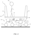
- FIG. 3 shows a state of the automated traveling pallet of the first embodiment, where a moving mechanism is driven and a grounding part is abutted against a ground surface;
- FIG. 6 is a diagram showing a schematic structure of an automated traveling pallet of the second embodiment
- FIG. 7 shows a state in which the vehicle body has been lowered in the automated traveling pallet of the second embodiment.
- FIG. 1 is a diagram showing a schematic structure of an automated traveling pallet of the first embodiment.
- An automated traveling cart 2 according to the present embodiment is an automated traveling cart having a pallet-type vehicle body 20 .
- the automated traveling cart 2 according to the present embodiment is referred to as an automated traveling pallet.
- the autonomous traveling ECU 41 has a function of communicating with control servers (not shown) by mobile communication such as 4G or 5G.
- the user of the automated traveling pallet 2 communicates with the control server using a user terminal, such as a smartphone or tablet PC, and transmits a desired departure point and a desired destination point to the control server.
- the control server selects an appropriate automated traveling pallet 2 from a plurality of available automated traveling pallets 2 , and transmits the departure point and the destination point to the selected automated traveling pallet 2 .
- the autonomous traveling ECU 41 creates a travel plan based on the departure point and the destination point received from the control server.
- the automated traveling pallet 2 is provided with a lighting device (not shown). LEDs are used as the lighting device. LED circuitry 45 for lighting the LEDs is supplied with power from the traveling control ECU 42 . The traveling control ECU 42 is supplied with power from the battery 40 . The LED circuitry 45 may light the LED at all times, or may light the LED depending on the ambient illuminance.
- the safety management ECU 46 includes a memory 46 b including at least one program 46 c and a processor 46 a coupled to the memory 46 b .
- the number of each of the memory 46 b and the processor 46 a may each be multiple.
- the processor 46 a controls the moving mechanism 64 of the jack 60 by executing the program 46 c .
- the safety management ECU 46 functions as a controller of the automated traveling pallet 2 according to the first embodiment. However, the function of a part as the controller of the automated traveling pallet 2 is executed by the autonomous traveling ECU 41 .
- a vehicle speed sensor 33 and a touch panel 38 are connected to the safety management ECU 46 .
- the safety management ECU 46 is supplied with power from the battery 40 .
- the power supply to the vehicle speed sensor 33 and the touch panel 38 is provided by the safety management ECU 46 .
- the power supply to the moving mechanism 64 is provided directly from the battery 40 .
- the automated traveling pallet 2 of the first embodiment may be modified as follows.
- the automated traveling pallet 2 of the first embodiment is not limited to a vehicle for performing automated traveling, it may be a vehicle for performing manual operation.
- the omni-directional wheel adopted in the automated traveling pallet 2 is not limited to omni-wheels.
- the front wheels 11 and the rear wheels 13 may be configured using other known omni-directional wheels, such as a mecanum wheels.
- the middle wheels 12 which is normal wheels, may be omitted.
- the arrangement and number of the jacks 60 are not limited. That is, for example, one jack 60 may be installed between the rear wheels 13 . Alternatively, one or a plurality of jacks 60 may be disposed around the front wheels 11 .
- the stop control may be executed in response to an operation request from the occupant 50 of the automated traveling pallet 2 .
- a button for requesting execution of the stop control may be displayed on the touch panel 38 .
- the safety management ECU 46 executes the stop control in response to the pressing of the button by the occupant 50 during the stop of the automated travel pallet 2 .
- the safety management ECU 46 executes the stop control after stopping the automated traveling pallet 2 in response to the occupant 50 pressing the button during the traveling of the automated traveling pallet 2 .
- the occupant 50 can perform riding or getting on and off with confidence in the automated traveling pallet 2 in the stop. This modification can also be applied to an automated traveling pallet according to another embodiment described later.
- stop determination of the automated traveling pallet 2 in the stop control is not limited to the method of using the vehicle speed sensor 33 . That is, for example, it may be determined stop of the automated traveling pallet 2 from the motor command value of the motors 44 of the left and right wheels 11 , 12 , 13 , it may be determined to stop from the signal of the other sensors. This modification can also be applied to an automated traveling pallet according to another embodiment described later.
- FIG. 6 is a diagram showing a schematic structure of an automated traveling pallet of the second embodiment.
- the automated traveling pallet 2 of the second embodiment is characterized in that it includes a ride height adjusting mechanism 66 as the moving mechanism.
- the ride height adjusting mechanism 66 is installed on top of the rocker 15 , the vehicle body 20 is mounted thereon. That is, in the automated traveling pallet 2 of the second embodiment, the ride height adjusting mechanism 66 and the damper 17 correspond to the suspension device connected between the spring upper structure and the spring lower structure.
- the ride height adjusting mechanism 66 includes an air bag and an electric compressor for feeding compressed air into the air bag.
- the ride height adjusting mechanism 66 can change the vertical position of the spring upper structure relative to the spring lower structure by adjusting the amount of compressed air fed into the air bag.
- the grounding part 68 is provided so as to protrude toward the ground surface from the bottom of the automated traveling pallet 2 .
- the grounding parts 68 are provided, for example, at two positions in the vicinity of the pair of the rear wheels 13 . When the ride height adjusting mechanism 66 is driven and the vehicle body 20 is lowered, the grounding part 68 is lowered accordingly.
- the grounding part 68 is set to a length that grounds the ground surface when the vehicle body 20 is lowered.
- the arrangement and the number of the grounding parts 68 are not limited as long as they are fixed to the vehicle body 20 . That is, for example, one grounding part 68 may be disposed at a position between the rear wheels 13 . Alternatively, one or a plurality of grounding parts 68 may be disposed around the front wheels 11 .
- the ride height adjusting mechanism 66 is not limited to an air suspension mechanism with an air bag, and other known ride height adjusting mechanisms may be employed.
Landscapes
- Engineering & Computer Science (AREA)
- Mechanical Engineering (AREA)
- Transportation (AREA)
- Structural Engineering (AREA)
- Civil Engineering (AREA)
- Life Sciences & Earth Sciences (AREA)
- Geology (AREA)
- Chemical & Material Sciences (AREA)
- Combustion & Propulsion (AREA)
- Control Of Position, Course, Altitude, Or Attitude Of Moving Bodies (AREA)
- Vehicle Cleaning, Maintenance, Repair, Refitting, And Outriggers (AREA)
- Vehicle Body Suspensions (AREA)
Abstract
Description
Claims (4)
Applications Claiming Priority (2)
| Application Number | Priority Date | Filing Date | Title |
|---|---|---|---|
| JP2020-169399 | 2020-10-06 | ||
| JP2020169399A JP7409278B2 (en) | 2020-10-06 | 2020-10-06 | Vehicles with omnidirectional wheels |
Publications (2)
| Publication Number | Publication Date |
|---|---|
| US20220105750A1 US20220105750A1 (en) | 2022-04-07 |
| US12194776B2 true US12194776B2 (en) | 2025-01-14 |
Family
ID=80931011
Family Applications (1)
| Application Number | Title | Priority Date | Filing Date |
|---|---|---|---|
| US17/492,962 Active 2043-05-21 US12194776B2 (en) | 2020-10-06 | 2021-10-04 | Vehicle equipped with omni-directional wheels |
Country Status (3)
| Country | Link |
|---|---|
| US (1) | US12194776B2 (en) |
| JP (1) | JP7409278B2 (en) |
| CN (1) | CN114379519B (en) |
Families Citing this family (3)
| Publication number | Priority date | Publication date | Assignee | Title |
|---|---|---|---|---|
| JP7347381B2 (en) * | 2020-09-11 | 2023-09-20 | トヨタ自動車株式会社 | stand-up vehicle |
| US20240092133A1 (en) * | 2021-02-18 | 2024-03-21 | Hitachi High-Tech Corporation | Mobile Robot |
| US20240083596A1 (en) * | 2022-09-14 | 2024-03-14 | Robert J. Henshaw | Aircraft boarding vehicle and methods of use |
Citations (13)
| Publication number | Priority date | Publication date | Assignee | Title |
|---|---|---|---|---|
| JPS5095924A (en) | 1973-12-25 | 1975-07-30 | ||
| JPS56167539A (en) | 1980-05-26 | 1981-12-23 | Kubota Ltd | Working vehicle |
| US4913458A (en) * | 1986-04-24 | 1990-04-03 | Hamilton Mark L | Surveillance vehicle control system |
| JPH07172340A (en) | 1993-12-20 | 1995-07-11 | Nippondenso Co Ltd | Travel truck |
| CN2602977Y (en) | 2003-03-03 | 2004-02-11 | 吕桂有 | Washboard type brake device for car |
| US20110162896A1 (en) * | 2010-01-04 | 2011-07-07 | Gillett Carla R | Mode of transportation type having inner-motorized omniwheel apparatus and method of control |
| US8235419B1 (en) * | 2009-04-10 | 2012-08-07 | Peter Anthony Giarrusso | Lateral stability system for a vehicle |
| JP2014046890A (en) | 2012-09-03 | 2014-03-17 | Araki Seisakusho:Kk | Omnidirectional moving truck having power assist function |
| JP2018125816A (en) | 2017-02-03 | 2018-08-09 | パナソニックIpマネジメント株式会社 | Video display system |
| US20190225195A1 (en) | 2018-01-23 | 2019-07-25 | Panasonic Intellectual Property Management Co., Ltd. | Mover and method for controlling the mover |
| JP2019127116A (en) | 2018-01-23 | 2019-08-01 | パナソニックIpマネジメント株式会社 | Mobile device and control method of the mobile device |
| US20200039477A1 (en) * | 2018-08-06 | 2020-02-06 | Jonathan Hernandez | Vehicle Built-in Electric Jack System |
| WO2020054733A1 (en) | 2018-09-11 | 2020-03-19 | Whill株式会社 | Travel route creation system |
Family Cites Families (5)
| Publication number | Priority date | Publication date | Assignee | Title |
|---|---|---|---|---|
| CN201245143Y (en) * | 2008-08-03 | 2009-05-27 | 张光裕 | Auxiliary brake for automobile |
| CN206338068U (en) * | 2016-12-16 | 2017-07-18 | 上海创力集团股份有限公司 | A kind of auxiliary traction brake apparatus of large gradient roadheader |
| JP7008210B2 (en) * | 2018-01-23 | 2022-01-25 | パナソニックIpマネジメント株式会社 | Mobile device and control method for mobile device |
| CN108382492A (en) * | 2018-02-13 | 2018-08-10 | 北京若唯世纪科技有限公司 | Six wheel sport(s) cars |
| CN210822281U (en) * | 2019-11-27 | 2020-06-23 | 中铁建电气化局集团第三工程有限公司 | Anti-sliding track platform lorry |
-
2020
- 2020-10-06 JP JP2020169399A patent/JP7409278B2/en active Active
-
2021
- 2021-09-24 CN CN202111118835.3A patent/CN114379519B/en active Active
- 2021-10-04 US US17/492,962 patent/US12194776B2/en active Active
Patent Citations (15)
| Publication number | Priority date | Publication date | Assignee | Title |
|---|---|---|---|---|
| JPS5095924A (en) | 1973-12-25 | 1975-07-30 | ||
| JPS56167539A (en) | 1980-05-26 | 1981-12-23 | Kubota Ltd | Working vehicle |
| US4913458A (en) * | 1986-04-24 | 1990-04-03 | Hamilton Mark L | Surveillance vehicle control system |
| JPH07172340A (en) | 1993-12-20 | 1995-07-11 | Nippondenso Co Ltd | Travel truck |
| US5535843A (en) | 1993-12-20 | 1996-07-16 | Nippondenso Co., Ltd. | Traveling carriage |
| CN2602977Y (en) | 2003-03-03 | 2004-02-11 | 吕桂有 | Washboard type brake device for car |
| US8235419B1 (en) * | 2009-04-10 | 2012-08-07 | Peter Anthony Giarrusso | Lateral stability system for a vehicle |
| US20110162896A1 (en) * | 2010-01-04 | 2011-07-07 | Gillett Carla R | Mode of transportation type having inner-motorized omniwheel apparatus and method of control |
| JP2014046890A (en) | 2012-09-03 | 2014-03-17 | Araki Seisakusho:Kk | Omnidirectional moving truck having power assist function |
| JP2018125816A (en) | 2017-02-03 | 2018-08-09 | パナソニックIpマネジメント株式会社 | Video display system |
| US20190225195A1 (en) | 2018-01-23 | 2019-07-25 | Panasonic Intellectual Property Management Co., Ltd. | Mover and method for controlling the mover |
| JP2019127116A (en) | 2018-01-23 | 2019-08-01 | パナソニックIpマネジメント株式会社 | Mobile device and control method of the mobile device |
| US20200039477A1 (en) * | 2018-08-06 | 2020-02-06 | Jonathan Hernandez | Vehicle Built-in Electric Jack System |
| WO2020054733A1 (en) | 2018-09-11 | 2020-03-19 | Whill株式会社 | Travel route creation system |
| US20210089037A1 (en) | 2018-09-11 | 2021-03-25 | WHILL, Inc. | Travel route creation system |
Also Published As
| Publication number | Publication date |
|---|---|
| CN114379519A (en) | 2022-04-22 |
| JP7409278B2 (en) | 2024-01-09 |
| US20220105750A1 (en) | 2022-04-07 |
| CN114379519B (en) | 2024-06-21 |
| JP2022061407A (en) | 2022-04-18 |
Similar Documents
| Publication | Publication Date | Title |
|---|---|---|
| US12194776B2 (en) | Vehicle equipped with omni-directional wheels | |
| JP7364763B2 (en) | Vehicle transport system | |
| KR101653968B1 (en) | Multiple zone sensing for materials handling vehicles | |
| CN205540279U (en) | Independently car is followed to human body | |
| US11458631B2 (en) | Vehicle transport apparatus | |
| KR20140074390A (en) | Steer control maneuvers for materials handling vehicles | |
| US20260028042A1 (en) | Sunlight processing for autonomous vehicle control | |
| US11724644B2 (en) | Vehicle and vehicle control system | |
| CN105501356A (en) | Two-wheel balance car | |
| CN112141585A (en) | Synchronous AGV (automatic guided vehicle) carrying system with cooperative active sensing and carrying method thereof | |
| US11845415B2 (en) | AGV having dynamic safety zone | |
| WO2022215115A1 (en) | Moving body | |
| JP2003073093A (en) | Unmanned forklift | |
| CN116279890B (en) | Dual-wheeled end-effector delivery robot | |
| JP2007038818A (en) | Automated guided vehicle | |
| CN218025270U (en) | Automatic guide fork truck | |
| US20220073080A1 (en) | Autonomous traveling cart | |
| CN210947951U (en) | Parking control device | |
| US20260015014A1 (en) | Vehicle mobility connection system and method for providing mobility service using the same | |
| JP7700692B2 (en) | Autonomous Vehicles | |
| JP7476751B2 (en) | Automated guided vehicles | |
| KR20260050086A (en) | Unmanned forklift and tilting control method thereof | |
| JPWO2020110248A1 (en) | Work equipment, work equipment control methods and programs | |
| CN117325601A (en) | Vehicle chassis balance control method, electronic device and storage medium | |
| JP2765261B2 (en) | Unmanned vehicle control device |
Legal Events
| Date | Code | Title | Description |
|---|---|---|---|
| AS | Assignment |
Owner name: TOYOTA JIDOSHA KABUSHIKI KAISHA, JAPAN Free format text: ASSIGNMENT OF ASSIGNORS INTEREST;ASSIGNORS:ISHII, DAISUKE;SATO, DAISUKE;IZU, HIROKI;AND OTHERS;SIGNING DATES FROM 20210806 TO 20210910;REEL/FRAME:057689/0443 |
|
| FEPP | Fee payment procedure |
Free format text: ENTITY STATUS SET TO UNDISCOUNTED (ORIGINAL EVENT CODE: BIG.); ENTITY STATUS OF PATENT OWNER: LARGE ENTITY |
|
| STPP | Information on status: patent application and granting procedure in general |
Free format text: DOCKETED NEW CASE - READY FOR EXAMINATION |
|
| STPP | Information on status: patent application and granting procedure in general |
Free format text: NON FINAL ACTION MAILED |
|
| STPP | Information on status: patent application and granting procedure in general |
Free format text: RESPONSE TO NON-FINAL OFFICE ACTION ENTERED AND FORWARDED TO EXAMINER |
|
| STPP | Information on status: patent application and granting procedure in general |
Free format text: NOTICE OF ALLOWANCE MAILED -- APPLICATION RECEIVED IN OFFICE OF PUBLICATIONS |
|
| STPP | Information on status: patent application and granting procedure in general |
Free format text: PUBLICATIONS -- ISSUE FEE PAYMENT VERIFIED |
|
| STCF | Information on status: patent grant |
Free format text: PATENTED CASE |