US12190857B2 - Metamaterial-based acoustic sensor beamforming - Google Patents
Metamaterial-based acoustic sensor beamforming Download PDFInfo
- Publication number
- US12190857B2 US12190857B2 US17/743,878 US202217743878A US12190857B2 US 12190857 B2 US12190857 B2 US 12190857B2 US 202217743878 A US202217743878 A US 202217743878A US 12190857 B2 US12190857 B2 US 12190857B2
- Authority
- US
- United States
- Prior art keywords
- acoustic
- projections
- array
- lens
- input
- Prior art date
- Legal status (The legal status is an assumption and is not a legal conclusion. Google has not performed a legal analysis and makes no representation as to the accuracy of the status listed.)
- Active, expires
Links
Images


Classifications
-
- G—PHYSICS
- G10—MUSICAL INSTRUMENTS; ACOUSTICS
- G10K—SOUND-PRODUCING DEVICES; METHODS OR DEVICES FOR PROTECTING AGAINST, OR FOR DAMPING, NOISE OR OTHER ACOUSTIC WAVES IN GENERAL; ACOUSTICS NOT OTHERWISE PROVIDED FOR
- G10K11/00—Methods or devices for transmitting, conducting or directing sound in general; Methods or devices for protecting against, or for damping, noise or other acoustic waves in general
- G10K11/18—Methods or devices for transmitting, conducting or directing sound
- G10K11/26—Sound-focusing or directing, e.g. scanning
- G10K11/30—Sound-focusing or directing, e.g. scanning using refraction, e.g. acoustic lenses
-
- A—HUMAN NECESSITIES
- A61—MEDICAL OR VETERINARY SCIENCE; HYGIENE
- A61B—DIAGNOSIS; SURGERY; IDENTIFICATION
- A61B8/00—Diagnosis using ultrasonic, sonic or infrasonic waves
-
- B—PERFORMING OPERATIONS; TRANSPORTING
- B06—GENERATING OR TRANSMITTING MECHANICAL VIBRATIONS IN GENERAL
- B06B—METHODS OR APPARATUS FOR GENERATING OR TRANSMITTING MECHANICAL VIBRATIONS OF INFRASONIC, SONIC, OR ULTRASONIC FREQUENCY, e.g. FOR PERFORMING MECHANICAL WORK IN GENERAL
- B06B1/00—Methods or apparatus for generating mechanical vibrations of infrasonic, sonic, or ultrasonic frequency
- B06B1/02—Methods or apparatus for generating mechanical vibrations of infrasonic, sonic, or ultrasonic frequency making use of electrical energy
- B06B1/06—Methods or apparatus for generating mechanical vibrations of infrasonic, sonic, or ultrasonic frequency making use of electrical energy operating with piezoelectric effect or with electrostriction
- B06B1/0644—Methods or apparatus for generating mechanical vibrations of infrasonic, sonic, or ultrasonic frequency making use of electrical energy operating with piezoelectric effect or with electrostriction using a single piezoelectric element
- B06B1/0662—Methods or apparatus for generating mechanical vibrations of infrasonic, sonic, or ultrasonic frequency making use of electrical energy operating with piezoelectric effect or with electrostriction using a single piezoelectric element with an electrode on the sensitive surface
- B06B1/067—Methods or apparatus for generating mechanical vibrations of infrasonic, sonic, or ultrasonic frequency making use of electrical energy operating with piezoelectric effect or with electrostriction using a single piezoelectric element with an electrode on the sensitive surface which is used as, or combined with, an impedance matching layer
-
- G—PHYSICS
- G01—MEASURING; TESTING
- G01N—INVESTIGATING OR ANALYSING MATERIALS BY DETERMINING THEIR CHEMICAL OR PHYSICAL PROPERTIES
- G01N29/00—Investigating or analysing materials by the use of ultrasonic, sonic or infrasonic waves; Visualisation of the interior of objects by transmitting ultrasonic or sonic waves through the object
- G01N29/22—Details, e.g. general constructional or apparatus details
- G01N29/221—Arrangements for directing or focusing the acoustical waves
-
- G—PHYSICS
- G01—MEASURING; TESTING
- G01S—RADIO DIRECTION-FINDING; RADIO NAVIGATION; DETERMINING DISTANCE OR VELOCITY BY USE OF RADIO WAVES; LOCATING OR PRESENCE-DETECTING BY USE OF THE REFLECTION OR RERADIATION OF RADIO WAVES; ANALOGOUS ARRANGEMENTS USING OTHER WAVES
- G01S15/00—Systems using the reflection or reradiation of acoustic waves, e.g. sonar systems
- G01S15/02—Systems using the reflection or reradiation of acoustic waves, e.g. sonar systems using reflection of acoustic waves
- G01S15/06—Systems determining the position data of a target
- G01S15/42—Simultaneous measurement of distance and other co-ordinates
-
- G—PHYSICS
- G01—MEASURING; TESTING
- G01S—RADIO DIRECTION-FINDING; RADIO NAVIGATION; DETERMINING DISTANCE OR VELOCITY BY USE OF RADIO WAVES; LOCATING OR PRESENCE-DETECTING BY USE OF THE REFLECTION OR RERADIATION OF RADIO WAVES; ANALOGOUS ARRANGEMENTS USING OTHER WAVES
- G01S15/00—Systems using the reflection or reradiation of acoustic waves, e.g. sonar systems
- G01S15/88—Sonar systems specially adapted for specific applications
- G01S15/89—Sonar systems specially adapted for specific applications for mapping or imaging
- G01S15/8906—Short-range imaging systems; Acoustic microscope systems using pulse-echo techniques
- G01S15/8909—Short-range imaging systems; Acoustic microscope systems using pulse-echo techniques using a static transducer configuration
-
- G—PHYSICS
- G01—MEASURING; TESTING
- G01S—RADIO DIRECTION-FINDING; RADIO NAVIGATION; DETERMINING DISTANCE OR VELOCITY BY USE OF RADIO WAVES; LOCATING OR PRESENCE-DETECTING BY USE OF THE REFLECTION OR RERADIATION OF RADIO WAVES; ANALOGOUS ARRANGEMENTS USING OTHER WAVES
- G01S7/00—Details of systems according to groups G01S13/00, G01S15/00, G01S17/00
- G01S7/52—Details of systems according to groups G01S13/00, G01S15/00, G01S17/00 of systems according to group G01S15/00
- G01S7/521—Constructional features
-
- G—PHYSICS
- G10—MUSICAL INSTRUMENTS; ACOUSTICS
- G10K—SOUND-PRODUCING DEVICES; METHODS OR DEVICES FOR PROTECTING AGAINST, OR FOR DAMPING, NOISE OR OTHER ACOUSTIC WAVES IN GENERAL; ACOUSTICS NOT OTHERWISE PROVIDED FOR
- G10K11/00—Methods or devices for transmitting, conducting or directing sound in general; Methods or devices for protecting against, or for damping, noise or other acoustic waves in general
- G10K11/18—Methods or devices for transmitting, conducting or directing sound
- G10K11/26—Sound-focusing or directing, e.g. scanning
- G10K11/34—Sound-focusing or directing, e.g. scanning using electrical steering of transducer arrays, e.g. beam steering
- G10K11/341—Circuits therefor
- G10K11/346—Circuits therefor using phase variation
-
- B—PERFORMING OPERATIONS; TRANSPORTING
- B06—GENERATING OR TRANSMITTING MECHANICAL VIBRATIONS IN GENERAL
- B06B—METHODS OR APPARATUS FOR GENERATING OR TRANSMITTING MECHANICAL VIBRATIONS OF INFRASONIC, SONIC, OR ULTRASONIC FREQUENCY, e.g. FOR PERFORMING MECHANICAL WORK IN GENERAL
- B06B1/00—Methods or apparatus for generating mechanical vibrations of infrasonic, sonic, or ultrasonic frequency
- B06B1/02—Methods or apparatus for generating mechanical vibrations of infrasonic, sonic, or ultrasonic frequency making use of electrical energy
- B06B1/06—Methods or apparatus for generating mechanical vibrations of infrasonic, sonic, or ultrasonic frequency making use of electrical energy operating with piezoelectric effect or with electrostriction
- B06B1/0607—Methods or apparatus for generating mechanical vibrations of infrasonic, sonic, or ultrasonic frequency making use of electrical energy operating with piezoelectric effect or with electrostriction using multiple elements
- B06B1/0622—Methods or apparatus for generating mechanical vibrations of infrasonic, sonic, or ultrasonic frequency making use of electrical energy operating with piezoelectric effect or with electrostriction using multiple elements on one surface
-
- G—PHYSICS
- G01—MEASURING; TESTING
- G01S—RADIO DIRECTION-FINDING; RADIO NAVIGATION; DETERMINING DISTANCE OR VELOCITY BY USE OF RADIO WAVES; LOCATING OR PRESENCE-DETECTING BY USE OF THE REFLECTION OR RERADIATION OF RADIO WAVES; ANALOGOUS ARRANGEMENTS USING OTHER WAVES
- G01S15/00—Systems using the reflection or reradiation of acoustic waves, e.g. sonar systems
- G01S15/88—Sonar systems specially adapted for specific applications
- G01S15/93—Sonar systems specially adapted for specific applications for anti-collision purposes
- G01S15/931—Sonar systems specially adapted for specific applications for anti-collision purposes of land vehicles
-
- G—PHYSICS
- G01—MEASURING; TESTING
- G01S—RADIO DIRECTION-FINDING; RADIO NAVIGATION; DETERMINING DISTANCE OR VELOCITY BY USE OF RADIO WAVES; LOCATING OR PRESENCE-DETECTING BY USE OF THE REFLECTION OR RERADIATION OF RADIO WAVES; ANALOGOUS ARRANGEMENTS USING OTHER WAVES
- G01S7/00—Details of systems according to groups G01S13/00, G01S15/00, G01S17/00
- G01S7/52—Details of systems according to groups G01S13/00, G01S15/00, G01S17/00 of systems according to group G01S15/00
- G01S7/52017—Details of systems according to groups G01S13/00, G01S15/00, G01S17/00 of systems according to group G01S15/00 particularly adapted to short-range imaging
- G01S7/52079—Constructional features
-
- H—ELECTRICITY
- H01—ELECTRIC ELEMENTS
- H01Q—ANTENNAS, i.e. RADIO AERIALS
- H01Q15/00—Devices for reflection, refraction, diffraction or polarisation of waves radiated from an antenna, e.g. quasi-optical devices
- H01Q15/0006—Devices acting selectively as reflecting surface, as diffracting or as refracting device, e.g. frequency filtering or angular spatial filtering devices
- H01Q15/0086—Devices acting selectively as reflecting surface, as diffracting or as refracting device, e.g. frequency filtering or angular spatial filtering devices said selective devices having materials with a synthesized negative refractive index, e.g. metamaterials or left-handed materials
Definitions
- the disclosure relates generally to abnormality detection in acoustic imaging sensors.
- Ultrasound has been used by animals to navigate through environments where optical sensing is not feasible. For instance, bats use ultrasound beams in an energy efficient manner to hunt millimeter size insects in complete darkness. Bats do so by constantly changing the direction of the ultrasound beam many times per second to ensonify the target with the beam's left and then right sides to properly identify the target and keep track of its often hieratic movement.
- Metamaterial research has approached the dynamical beam forming and steering challenge from a different perspective. Metamaterials have acoustic properties that can be dynamically modified as desired. However, for most applications of interest, large samples of metamaterials are unfortunately needed.
- an acoustic lens to steer an acoustic beam includes a first structure, a second structure spaced from the first structure, an array of projections disposed between the first and second structures, each projection of the array of projections extending from the first structure toward the second structure to define a respective gap between the projection and the second structure, and an actuator configured to move the first structure, the second structure, or the array of projections for collective adjustment of the respective gaps of the array of projections.
- Each projection is configured to define one or more respective unit cells, each unit cell having a sub-wavelength size relative to the acoustic beam to establish an effective refractive index profile for the acoustic beam between the first and second structures.
- the actuator is configured such that the collective adjustment of the respective gaps varies across the array of projections to spatially modify the effective refractive index profile to steer the acoustic beam.
- an acoustic device includes a transducer configured to generate an input sound wave, a waveguide coupled to the transducer to receive the input sound wave, a beam former including an input aperture coupled to the waveguide, an output aperture, and a gradient index lens disposed between the input and output apertures, the gradient index lens having a continuous refractive index profile.
- the gradient index lens includes a first structure, a second structure spaced from the first structure, an array of projections disposed between the first and second structures, each projection of the array of projections extending from the first structure toward the second structure to define a respective gap between the projection and the second structure, and an actuator configured to move the first structure, the second structure, or the array of projections for collective adjustment of the respective gaps of the array of projections.
- the actuator is configured such that the collective adjustment of the respective gaps varies across the array of projections to spatially modify an effective refractive index of the gradient index lens.
- the actuator is configured to move the second structure.
- One of the first and second structures is flexible.
- the actuator is configured to rotate one of the first and second structures about an axis parallel to a propagation direction of the acoustic beam prior to steering.
- One of the first and second structures includes an array of piezoelectric patches.
- the actuator includes a plurality of voltage sources configured to apply a position-dependent voltage to the array of piezoelectric patches.
- the actuator includes a plate that acts on one of the first and second structures.
- Each projection of the array of projections has a respective length.
- the respective length of the projections varies along a propagation direction of the acoustic beam to provide impedance matching.
- the first and second structures define input and output apertures through which the acoustic beam enters and exits the slot, respectively.
- the array of projections includes input and output impedance matching sections at the input and output apertures, respectively.
- the projections have respective heights in the input and output impedance matching sections that progressively range up to, and down from, a primary height of the projections, respectively.
- the first and second structures include first and second plates, respectively.
- the array of projections are disposed in a periodic arrangement.
- the transducer is a point source such that the input sound wave is cylindrical.
- the waveguide includes a parallel plate waveguide configured to direct the input sound wave to the input aperture of the acoustic lens.
- the actuator is configured to rotate one of the first and second structures about an axis parallel to a propagation direction of the acoustic beam prior to steering.
- the collective adjustment of the respective gaps varies in a direction transverse to a direction of propagation through the input aperture.
- Each projection of the array of projections has a respective length. The respective length of the projections varies along a propagation direction of the acoustic beam to provide impedance matching.
- the array of projections includes input and output impedance matching sections at the input and output apertures, respectively.
- the projections have respective heights in the input and output impedance matching sections that progressively range up to, and down from, a primary height of the projections, respectively.
- the first and second structures include first and second plates, respectively.
- the array of projections are disposed in a periodic arrangement.
- FIG. 1 depicts a schematic view of an acoustic device having a metamaterial acoustic lens with a gradient index (GRIN) profile for beam steering in accordance with one example, along with a schematic representation of phase advances of an acoustic ray propagating through the acoustic GRIN lens and a plot of phase profiles of the GRIN lens for beam forming and steering.
- GRIN gradient index
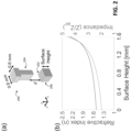
- FIG. 2 depicts a schematic, perspective view of a unit cell of a metamaterial acoustic lens having a gap or perforation in accordance with one example, along with a graphical plot of effective refractive index and impedance as a function of gap or perforation size.
- FIG. 3 depicts a partial, schematic, perspective view of an acoustic lens having impedance matching sections in accordance with one example, along with cross-sectional views of acoustic lens with different gap sizes, and graphical plots of the phase advance, amplitude, and geometry profile of the acoustic lens.
- FIG. 4 depicts perspective views of an acoustic device having a metamaterial acoustic lens with a gradient index profile for beam steering in accordance with one example, along with graphical plots of acoustic pressure fields generated by the metamaterial acoustic lens.
- FIG. 5 depicts graphical, polar plots of far-field pressure distributions for acoustic devices having a metamaterial acoustic lens with a gradient index profile for beam steering in accordance with one example.
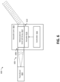
- FIG. 6 depicts a block diagram of an acoustic device having a metamaterial acoustic lens in accordance with one example.
- FIG. 7 depicts a schematic view of an acoustic lens having an array of piezoelectric patches driven by a plurality of voltage sources in accordance with one example.
- the acoustic lens includes an assembly of structures that includes an array of projections, with each projection defining one or more unit cells, each unit cell having a sub-wavelength size relative to the acoustic beam.
- the sub-wavelength size establishes an effective refractive index profile (e.g., of a metamaterial of the acoustic lens) for the acoustic beam.
- the disclosed devices may be configured as a biosonar-like device that takes a diverging acoustic wave, e.g., produced by a ultrasound transducer, and passes the wave through a tunable acoustic gradient index (GRIN) lens to form collimated, directive beams that may then be steered in prescribed directions.
- GRIN a tunable acoustic gradient index
- the lenses of the disclosed devices have a sufficiently large aperture to form a highly directive beam.
- the lenses also impose a prescribed inhomogeneous phase advance throughout the lens. Furthermore, the sound phase advance through the lens varies drastically from one part of the device to the next.
- the disclosed devices also provide a sufficiently high phase advance gradient to allow for a thin lens.
- the disclosed devices also address another challenge presented by large phase gradients—i.e., resonances that impose narrow band operation.
- narrow band operation is undesirable in acoustics because most applications (e.g., sonar—including biosonar, medical imaging, etc.) rely on the manipulation and processing of short pulses and thus involve broadband operation.
- the scalability of the acoustic lens of the disclosed devices allows the disclosed devices to be capable of supporting broadband operation, as described herein.
- the disclosed acoustic devices may be useful as ultrasound or other acoustic sensors for various applications, including, for instance, those involving scanning and imaging of the surrounding environment, such as sensors for autonomous or semi-autonomous vehicles, ultrasound medical imaging, and sonar.
- the disclosed acoustic sensors are useful in such applications because sound is far reaching in various types of media, such as air and water.
- the disclosed acoustic sensors maintain efficiency in adverse weather unlike cameras, LIDAR, and radar.
- the disclosed acoustic devices differ from past acoustic sensors, which have either very low ranges (e.g., past ultrasound sensors for autonomous vehicles), or involve arrays of speakers and are thus expensive, power hungry, and low-resolution (e.g. sonar, ultrasound imaging).
- the disclosed acoustic devices may provide sensors in which sound produced by a single acoustic source (e.g., a speaker or piezoelectric transducer) is focused into a beam by a reconfigurable acoustic lens. Adjustment of the geometry of the acoustic lens (e.g., sub-millimeter dynamical deformations of the lens geometry) direct the beam in desired directions without rotating the entire device, which leads to significant power reduction and increased sensor reliability.
- the sound scattered by the environment may be captured by the acoustic lens and formed into an image. Non-linear effects in the lens structure may also be used to improve sensor resolution, as described herein.
- the metamaterial of the disclosed acoustic devices has scalable properties that are dynamically reconfigurable on-demand and in real time.
- Past metamaterials have unfortunately been limited to tuning very small samples composed of at most few dozen unit cells. Past approaches have thus not been scalable to larger structures.
- the disclosed acoustic devices may include a mechanism that involves only a single controller to change the acoustic properties of a large-scale, or bulk metamaterial assembly. The mechanism relies on an array of unit cells. A large collection of the unit cells may have acoustic properties collectively set through adjustments (e.g., submillimeter deformations) of a structure of the assembly, such as a flexible plate or other component. Examples of the acoustic devices are described below that demonstrate a reconfigurable metamaterial-based device for highly directive ultrasonic beam forming and steering at 40 kHz.
- the disclosed acoustic devices include a large amount (e.g., about ten thousand) unit cells reconfigured simultaneously, or collectively, to implement desired, inhomogeneous gradients (as opposed to discrete changes) of the refractive index.
- large scale, bulk structures may be provided with a much smaller per cell acoustic response than thin structures (e.g., metasurfaces), and thus do not rely on narrowband resonances and are consequently broadband.
- the disclosed examples exhibit a bandwidth at least an order of magnitude larger than past metamaterials, including metasurfaces.
- the reconfigurability of the bulk metamaterials of the disclosed acoustic devices supports wave control over large scales and broadband operation.
- the disclosed acoustic devices may be used in connection with a wide variety of frequency ranges, media, and use contexts.
- the disclosed acoustic devices are also not limited to parallel plate structures or assemblies.
- the disclosed devices may use a wide variety of structures to support and otherwise form a metamaterial-based acoustic lens.
- the nature of the configurability may also vary considerably.
- the geometry of the lens may be adjusted via tilting, deformation, vibration, and/or other movement.
- the adjustments may be driven by a wide variety of actuators, including, for instance, various electric motor- or electromagnet-based actuators.
- the shape, construction, and other characteristics of the projections may also vary from the examples shown.
- the projections may be composed of, or otherwise include, a piezoelectric material such that the length (or height) of the projections varies.
- the actuator of acoustic lens may include one or more voltage sources to drive the piezoelectric material.
- the disclosed devices may include multiple actuators.
- the devices may include two or more actuators directed to moving respective portions of the structures, e.g., in opposite directions.
- two or more pin- or probe-shaped actuators may push a sheet- or plate-shaped structure, such as an elastic sheet, to a varying extent.
- the pin-shaped actuators may be elongated or otherwise extend along the propagation direction.
- the structure may be driven by a pair of actuators may be disposed at either side or end of the structure.
- Each of the actuators in such cases may nonetheless be considered to collectively adjust the gaps for an array of projections, even though the device may include further projections collectively addressed by another one of the actuators.
- the disclosed devices may thus be considered to include multiple arrays (or sub-arrays) of projections.
- the projections in each such array (or sub-array) are collectively, rather than individually, actuated and controlled, as described herein.
- metamaterial-based assemblies that manipulate acoustic properties of large material structures at ultrasonic and other frequencies with a single controlling element. Tuning may be implemented by small (submillimeter) deformations of a single structural element that spans the metamaterial volume.
- the mechanism was demonstrated experimentally though examples in which an ultrasonic beam steering device operated in a bandwidth of 10% centered at 40 kHz.
- the example device is 12 wavelengths in width, 6 wavelengths thick, and includes more than 7800 reconfigurable unit cells, which is two orders of magnitude more unit cells than possible with other methods.
- the metamaterial-based assembly is designed to have small insertion loss enabled by the non-resonant nature of the unit cells thereof and by using impedance matching layers or sections.
- the ultrasound beam formers described herein produce very directive beams that can scan directions spanning 30 degrees.
- the single transducer approach coupled with the sub-millimeter actuation of one structural element makes the disclosed devices ultra-low power.
- the reconfigurable aspect of the disclosed devices opens the path to large-scale, smart materials for ultrasonic imaging and other applications.
- Part (a) of FIG. 1 depicts a device 100 that provides an example of the reconfiguration of the behavior of bulk metamaterials.
- an inhomogeneous refractive index profile is established inside a large metamaterial block or lens 102 of the device 100 .
- the metamaterial-based device 100 replicates the ability of biosonar-capable animals to raster scan the environment with very directive ultrasound beams.
- the beam forming and steering is done by the metamaterial lens 102 whose inhomogeneous refractive index profile is dynamically changed.
- the device 100 may have an aperture of 12 wavelengths (e.g., at the operational frequency of 40 kHz), which is one order of magnitude larger than other static or reconfigurable acoustic lenses.
- the lens 102 includes a metamaterial made of non-resonant unit cells, which have much weaker acoustic responses than the resonant cells used in traditional acoustic lenses. Consequently, the metamaterial may be thick in the propagation direction in order to produce the acoustic phase advance used for beam forming and steering.
- the lens is 6 wavelengths in the propagation direction, i.e. one order of magnitude larger than other designs.
- continuous phase advances throughout the lens 102 are provided, as opposed to the step-wise approximations of these profiles implemented by other metamaterials.
- FIG. 1 Part (a) of FIG. 1 shows the structure of the ultrasound device 100 .
- Cylindrical waves 104 produced by an omnidirectional transducer are guided by a parallel-plate waveguide to an input aperture 106 of the reconfigurable, metamaterial-based GRIN lens 102 .
- the reconfigurable metamaterial-based GRIN lens 102 transforms the cylindrical waves 104 from the point source of the transducer into a beam 108 of plane waves and continuously steers the beam 108 .
- the GRIN lens 102 thus forms a collimated beam propagating under an angle with respect to the normal direction x by establishing a refractive index profile inside the lens 102 that varies in the transverse y direction according to the following expression:
- n ⁇ ( y ) n 0 ⁇ sech ( ⁇ ⁇ y 2 ⁇ ( L f + L x ) ) + y ⁇ sin ⁇ ( ⁇ s ) L y
- L f is the focal length of the lens and the distance between the lens input aperture 106 and the transducer
- L x and L y are the lens dimensions in the x and y directions
- n 0 is the refractive index in the middle of the lens 102 .
- the first term of the equation represents the refractive index of a gradient index (GRIN) having a hyperbolic tangent refractive index profile. This profile may be used to reduce lens aberrations and thus improve the quality of the collimated beam produced by the lens.
- This refractive index component corresponds to a phase advance in the lens for normal incidence of—
- ⁇ ′ ( y ) k air ⁇ L x ⁇ n 0 ⁇ sech ( ⁇ 2 ⁇ y L f + L x )
- the second term of the equation represents the additional refractive index used to steer the propagating wave.
- ⁇ ( y ) k air y sin ⁇ s
- the refractive index for steering is obtained by dividing the phase advance by k air L x , which yields the second term of the equation above.
- the maximum index of refraction realizable with non-resonant metamaterial cells is approximately 2, which puts a constraint on the lens dimensions.
- L x 5 cm
- L y 10 cm
- L z 15 cm, which provides a good tradeoff between the lens size and its performance.
- Other dimensions may be used.
- the lens 102 is designed to steer beams in, for instance, a range of +15 degrees to ⁇ 15 degrees
- the plane wave decomposition of the acoustic field through the lens 102 may contain wave vectors with negligible components in they direction.
- Part (b) of FIG. 1 shows a number of phase profiles of the metamaterial-based lens 102 .
- part (b) depicts a plot of the variation of the phase advance along the direction y for 0 degrees and 15 degrees. The plot shows that high phase advances of almost 1100 degrees are needed through the lens 102 .
- Most past acoustic lenses leverage the periodicity of the phase to implement discontinuous refractive index profiles to impose phase advances in the range 0 to 360 degrees similar to fisheye lenses in optics. This typically means that the lens is divided into sections, and each lens section must be configured independently to obtain dynamic steering. In this case, instead, to configure the lens 102 via a single controller, the lens 102 has a continuous refractive index profile. An unprecedentedly high phase advance may thus be attained by increasing the lens thickness in the propagation direction, e.g., to 6 wavelengths.
- the beam forming and steering element is implemented with arrangements of subwavelength (e.g., highly subwavelength) unit cells that form an effective medium with the configurable refractive index profile shown in part (b) of FIG. 1 .
- unit cell dimensions of 0.8 mm by 0.8 mm may be used in one example. In this case, the cell is more than 10 times smaller than the wavelength of 40 kHz sound in air (8.6 mm).
- the unit cell width of 0.8 mm in a 10 cm by 5 cm metamaterial results in 7,800 unit cells that are configured simultaneously or collectively (as opposed to individually or independently) to implement the inhomogeneous refractive index profiles (e.g., part (b) of FIG. 1 ).
- the sheer number of cells to be tuned or adjusted makes previous cell configuration mechanisms that involved controlling each cell or small groups of cells independently unfeasible.
- Part (a) of FIG. 2 schematically shows a unit cell 200 in accordance with one example.
- the unit cell 200 may be used in a metamaterial-based lens, such as the lens 102 of FIG. 1 .
- a bottom surface 202 of the unit cell 200 moves vertically to tune acoustic properties of the unit cell.
- Part (b) of FIG. 2 shows the effective refractive index and normalized impedance of the unit cell 200 over a range of surface heights.
- the cell structure may be configured to facilitate the adjustment of a large number of unit cells.
- Part (a) of FIG. 2 shows the structure of the unit cell 200 .
- the functionality of the unit cell 200 is based on the observation that sound propagating through perforated solids is delayed by a significant amount and thus perforated solids behave as high refracted index media. The delay increases while the gap or perforation size (indicated with d) decreases.
- the assembly includes two separate inclusions 204 , 206 . In some cases, one inclusion is fixed, while the other is mobile. In the example shown, the inclusion 204 (e.g., top inclusion) is fixed and the inclusion 206 (e.g., the bottom surface 202 ) is mobile.
- the effective refractive index established by the unit cell 200 is adjusted by moving the lower inclusion 206 , or component, relative to the top inclusion 204 , or part.
- This example unit cell assembly strikes a balance between obtaining high phase advances through the cell 200 , thereby reducing absorption, and maintaining good manufacturability.
- the roles of the top and bottom inclusions or components 204 , 206 may be reversed.
- both inclusions or components 204 , 206 may be mobile, including, for instance, cases in which one of the components is vibrating.
- Part (b) of FIG. 2 shows the effective refractive index and insertion loss (due to both absorption and reflection) versus perforation size d for the device 200 shown in part (a) of FIG. 2 . These values are calculated from the incident, reflected, and transmitted pressures obtained from simulations using a method widely used for calculating effective acoustic properties of metamaterials.
- the minimum gap size d may be 0.4 mm, which ensures a maximum absorption of approximately 0.15 dB/cell.
- this choice limits the refractive index to values under 2, and thus the phase advance defined in the equation above is limited to values below 16 degrees. Consequently, the lens uses more than 60 unit cells in the propagation direction to achieve the desired phase advance of 1100 degrees. This equates to a total expected absorption loss of 8 dB. Remarkably, this is significantly less than is capable of being obtained in a much thinner metasurface that would force sound to propagate through fluid-solid interface layers of high thermoviscous loss.
- a second source of insertion loss involves reflections of poorly matched unit cells to the air background.
- the assembly may include impedance matching sections at the input and output apertures, examples of which are described hereinbelow.
- Part (a) of FIG. 3 shows the geometry of a reconfigurable metamaterial GRIN lens 300 in accordance with one example.
- the lens thickness (L x ) and width (L y ) are 5 cm and 10 cm respectively.
- the lens height (L x ) of the lens a small height may result in excessive thermal and viscous loss due to narrow path.
- a height larger than the wavelength may allow multiple modes of sounds to propagate through the lens. Therefore, the lens height may be set to be 3 mm in this example, which is smaller than the wavelength but large enough to keep the losses small. Other heights may be used.
- the highly subwavelength 0.8 mm by 0.8 mm unit cells are composed of 0.41 mm thick (w 1 ) inclusions with 0.39 mm gaps (w 2 ), but the dimensions may vary.
- the 0.41 mm thickness and 0.39 mm gaps are useful because if the gaps are too narrow, then the sounds passing through that region may experience excessive thermal and viscous loss from narrow channel.
- the inclusion height may be 1.2 mm in this case to compromise between phase delay range and thermal and viscous losses. Other heights may be used.
- the lens 300 may include impedance matching sections 302 because the unit cells with high refractive index have much larger impedance than air. This part of the lens 300 is useful because, without impedance matching, only a small portion of incident sound may be transmitted due to excessive insertion loss, making the lens not practical. Therefore, in this example, each impedance matching section 302 includes 4 mm deep or thick matching layers with inclusion height increasing gradually by 0.2 mm. In some cases, a bottom surface 304 of the lens may vary linearly to prevent sudden increase of impedance and thus minimize insertion loss.
- changing perforation size d changes wave length inside the metamaterial and thus changes phase at the exit.
- Phase and amplitude of the transmitted acoustic wave for the entire surface height range used in the lens design are presented in part (c) of FIG. 3 .
- the cross section confirms that considerable phase change of about 7 ⁇ is achievable with about 1.5 mm deflection of the surface.
- the amplitude of transmitted waves is small for gap sizes (d) smaller than about 0.9 mm.
- the impedance matching sections 302 become less efficient as the gap size decreases because the impedance gap between the plateau region and outside the lens increases. Also, losses from air viscosity and thermal effects are more dominant for narrow channels as well.
- transmitted pressure is large.
- phase change is exponential, and transmitted pressure is small.
- the lens 300 includes a fixed top element 306 containing fins 308 of height h and width w 1 spaced a distance w 2 apart. Each fin 308 is disposed in a respective row that runs along the direction of the y-axis shown in FIG. 3 . Each fin 308 may thus include, and be realized by stacking, multiple unit cells (e.g., 190 cells) in the y-axis direction.
- the lens 300 provides a steerable angle between ⁇ 20 degrees and 20 degrees for a steerable range of 40 degrees.
- the bottom element 304 is a flexible component whose topology is chosen to realize the desired behavior of the metamaterial.
- a configurable beam former may have the desired phase advance shown in part (b) of FIG. 1 .
- the equation above may be used to compute the refractive index versus position inside the lens, and part (b) of FIG. 2 may be used to map the refractive index to the gap size d for each unit cell and thus find the shape of the flexible component throughout the metamaterial.
- the refractive index varies in the transverse y direction only. Therefore, the topology of the flexible element 304 varies only in the y direction in this implementation. In other cases, additional variation may be provided.
- Part (b) of FIG. 3 shows the ability of the metamaterial to control the phase advance in a range 0 to 1260 degrees.
- Numerical simulations performed with Comsol Multiphysics that take into account the thermoviscous losses inside the complicated structure show that the transmission coefficient remains above 0.5 across the entire range.
- Part (c) of FIG. 3 shows the topology of the flexible component 304 versus y for two steering angles of 0 degrees and 20 degrees.
- These example topologies exhibit several useful aspects of the small phase advance per unit cell afforded by bulk metamaterials.
- the flexible component is smooth, has a small gradient in x and y, and the maximum deformation is below 1.5 mm.
- a variety of different actuators or mechanisms may be used to change the shape of the flexible component(s) to match or attain the desired profiles, e.g., the profiles shown in part (b) of FIG. 3 .
- the profile corresponding to the device forming a beam along the normal to the exit aperture (0 degree steering) is implemented.
- Rotations of the flexible element about the x direction may be used to approximate the topology of the flexible element used for other steering angles.
- Part (b) of FIG. 3 illustrates this example for a steering angle of 15 degrees. The compromise is a small reduction in the steerable angle (5 degrees) due to the rotated element being raised more than its ideal surface. Nevertheless, the example device maintains its ability to steer directive ultrasound beams over the range of ⁇ 15 to +15 degrees.
- the disclosed devices are capable of broadband wave front manipulation. Further details regarding such broadband capability are provided below in connection with one or more examples.
- Part (a) of FIG. 4 depicts an example device 400 for evaluating the performance of a bulk metamaterial lens 402 of the device 400 .
- an ultrasonic transducer 404 (Murata MA40S4S) is located at the narrower end of a funnel-shaped parallel plate waveguide 406 .
- the transducer 404 emitted an omnidirectional pulse centered at 40 kHz into the funnel-shaped parallel plate waveguide 406 .
- the waveguide 406 guides the sound towards the input aperture of the reconfigurable metamaterial lens 402 .
- the pulses propagated through the waveguide 406 and entered the metamaterial-based lens 402 , which transformed the waves to plane waves with different directions, transmitting them into the open air.
- the spatial-temporal distribution of the beam formed by the lens 402 is measured in a highlighted region 408 using a broadband microphone.
- Part (b) of FIG. 4 shows the metamaterial structure and assembly of the lens 402 in this example.
- the lens 402 includes a fixed element (top) 410 and a mobile element (middle) 412 .
- the assembled lens 402 is also shown to depict a slit 414 through which sound enters the metamaterial-based lens 402 .
- the fixed (top) and movable components (middle) 410 , 412 are placed one on top of one another to form the ultrasonic lens 402 .
- the slit 414 between the two components 410 , 412 is also representative of the output aperture of the lens 402 .
- the fixed component 410 includes an array of fin-shaped projections 416 .
- the fin-shaped projections 416 are highlighted for ease in depicting how each fin-shaped projection 416 is disposed along a respective row as shown.
- the fixed component 410 also includes an impedance matching section 418 in which the height (or length) of the fins is progressively varied.
- the rows of the fin-shaped projections 416 in the impedance matching section 418 appear to be progressively shorter, when, in fact, all of the rows shown have the same length. The appearance results from the variance in height (or length of projection) of the fins and the particular perspective view of FIG. 4 portion.
- Part (c) of FIG. 4 shows measured acoustic pressure fields in front of the lens 402 for steering angles of 0 and 15 degrees (see highlighted regions). These measured fields were propagated numerically in the far-field using the Green's function method. The results show collimated, highly directive beams propagating in the desired directions.
- Part (a) of FIG. 5 shows the polar plots of the far-field pressure distributions generated by the example device 400 of FIG. 4 .
- the distributions were measured 25 cm (29 wavelengths) away from the lens 402 ( FIG. 4 ).
- the distributions were normalized to the fields measured after replacing the lens 402 with a parallel-plate waveguide of the same vertical extent.
- the measurements confirm the excellent directivity of the collimated beams produced by the metamaterial-based device 400 for all directions of propagation (the extreme 0 and 15 degree cases are shown in the figure) while maintaining negligible unwanted side lobes.
- Part (b) of FIG. 5 shows the representative case of a 15 degree beam angle for frequencies between 39 and 42 kHz, which confirms that the beam performance is preserved over a 7% band. Numerical simulations suggest that the lens is even more broadband, e.g., having a band of 30%.
- the disclosed devices present a technique to reconfigure the acoustic behavior of bulk metamaterials using only one actuation element (controller), which allows setting desired spatial distributions of material parameters of large metamaterial structures or assemblies.
- the reconfiguration involves a unit cell that includes two components, e.g., one fixed and one mobile.
- the cell may be configured such that small actuations of the mobile component result in significant phase changes as sound propagates through the cell.
- the mobile components form a single flexible element whose spatial topology can be controlled in real-time to manipulate the spatial acoustic properties of the metamaterial.
- the examples described herein exhibit a low loss, large aperture beam forming and steering device operating in a 10% bandwidth centered at 40 kHz.
- the large aperture resulted in a narrow beam with small side lobes projected by the device and therefore the device has a very high gain.
- the device was configured to minimize the insertion loss by lowering the thermoviscous absorption, which is a significant challenge in the ultrasound regime, and through the use of metamaterial matching layers.
- the metamaterial reconfiguration is implemented through rotation of a bottom plate having a carefully designed topology.
- the bottom plate may be stiff with a non-flat surface, the rotation of which may achieve the movement depicted in, for instance, part (c) of FIG. 3 .
- such movement may be achieved by vibrating a flat component.
- Rotations of this plate of less than 1.7 degrees support redirection of the narrow beam in prescribed directions covering a range of 30 degrees.
- the ability to control the material parameters in large volumes enables significant acoustic phase front manipulations without the use of resonances, and thus solves one of the most fundamental limitations of thin acoustic metamaterials (metasurfaces).
- the latter need resonances to implement the acoustic wave manipulation over the short distance of several unit cells, and thus have narrow operational bandwidths, e.g., often under 1%. Therefore, they are not suitable for most acoustics applications, such as sonar and medical imaging, which rely on broadband pulses.
- the ability to manipulate acoustic waves in real time in much thicker devices means that each unit cell is allowed to produce a much weaker response than can be realized with non-resonant structures, while maintaining overall functionality. Consequently, the disclosed devices are capable of accommodating a desired bandwidth of ultrasound applications, as well as applications typically entrusted to electromagnetic waves such as object identification, target tracking, and landscape mapping.
- FIG. 6 depicts an acoustic device 600 in accordance with one example.
- the device 600 includes an acoustic lens or beam former 602 .
- the acoustic lens 602 may be configured as described herein.
- the device 600 includes a transducer 604 configured to generate an input sound wave.
- the transducer 604 is or otherwise includes a point source such that the input sound wave is cylindrical.
- the device 600 also includes a waveguide 606 coupled to the transducer 604 to receive the input sound wave.
- the waveguide 606 is or otherwise includes a parallel plate waveguide configured to direct the input sound wave to the acoustic lens 602 .
- the acoustic lens 602 includes an input aperture 608 coupled to the waveguide 606 , an output aperture 610 , and a gradient index lens assembly 612 disposed between the input and output apertures.
- the gradient index lens assembly 612 is or otherwise includes a metamaterial-based unit cell array.
- the gradient index lens assembly includes a first plate or other structure, a second plate or other structure spaced from the first structure, and an array of fins or other projections disposed between the first and second structures. As described herein, each projection of the array of projections extends from the first structure toward the second structure to define a respective gap between the projection and the second structure.
- each projection of the array of projections is configured to define a respective unit cell, with each unit cell having a sub-wavelength size relative to the acoustic beam to establish an effective refractive index profile for the acoustic beam between the first and second structures.
- the acoustic lens 602 (and/or the gradient index lens assembly 612 ) also includes an actuator 614 configured to move the first structure, the second structure, or the array of projections for collective adjustment of the respective gaps of the array of projections.
- the actuator 614 is configured such that the collective adjustment of the respective gaps varies across the array of projections to spatially modify an effective refractive index of the gradient index lens.
- the actuator is configured such that the collective adjustment of the respective gaps varies across the array of projections to spatially modify the effective refractive index profile to steer the acoustic beam.
- the actuator 614 is controlled or driven by a controller 616 .
- the controller 616 may be or otherwise include a microcontroller, a field programmable gate array (FPGA), or other processor.
- the actuator 614 and the controller 616 may be integrated to any desired extent.
- the actuator 614 is configured to move the second structure.
- the actuator 614 may act on a flexible plate or other component, such as the flexible bottom described hereinabove.
- the actuator 614 may rotate the plate or other structure. The rotation may be about an axis parallel to a propagation direction of the acoustic beam prior to steering.
- the actuation may involve or include piezoelectric deformation of one or more structures.
- one of the first and second structures may include an array of piezoelectric patches or other elements. Pairs of the patches are disposed on opposite sides of a plate or other central structure.
- the actuator may include a voltage source configured to apply a position-dependent voltage across the pair of piezoelectric elements.
- the array may be used to vibrate one of the structures, e.g., the structure without the fins or other projections.
- the vibration mode may vary in the direction of sound propagation and/or the direction transverse to the direction of sound propagation.
- a voltage is applied to create a piezoelectric force that excites a mode of the lens (e.g., one of the plates).
- the mode shape may not be constant over space.
- the mode may have locations of larger displacement and locations of lower displacement.
- the shape of the mode may be tailored, e.g., by tailoring the mass and stiffness distribution (in space, e.g., x, y, z) in the plate.
- the applied voltage creates a motion that is tailored as desired.
- a single voltage creates a displacement correlated in space, but not constant in space (with a desired spatial distribution).
- the actuator 614 may act on the structure(s) of the assembly directly or indirectly.
- the actuator 614 may include a plate that acts on one of the first and second structures.
- the collective adjustment of the respective gaps implemented by the actuator 614 may vary in a direction transverse to a propagation direction of the acoustic beam prior to steering.
- the respective length (or height) of the projections in the array may vary along a propagation direction of the acoustic beam to provide impedance matching.
- the array of projections may include input and output impedance matching sections at the input and output apertures 608 . 610 , respectively.
- the respective heights of the projections in the input and output impedance matching sections progressively range up to, and down from, a primary height of the projections, respectively.
- FIG. 7 depicts an acoustic lens 700 that includes a plate or other structure 702 (e.g., a flexible component of the acoustic lens) with an array of piezoelectric patches 704 in accordance with one example.
- an actuator of the acoustic lens 700 includes a plurality of voltage sources (V 1 , V 2 , . . . V N ) configured to apply a position-dependent voltage to the array of piezoelectric patches 704 .
- Each patch 704 may thus be driven by a respective voltage source of the plurality of voltage sources.
- the acoustic lens 700 includes an array of projections (not shown in FIG. 7 ) that define respective gaps. The number of projections may exceed (e.g., greatly exceed) the number of piezoelectric patches. Consequently, the array of piezoelectric patches are arranged to vibrate or otherwise move the structure for the collective adjustment of the gaps, as opposed to moving each projection individually.
- the multiple voltage sources and corresponding patches of the actuator may implement the collective adjustment of the gaps by imposing a vibration mode on the plate or other flexible structure or component.
- Using multiple voltage sources and corresponding patches allows a wide variety of vibration modes to be realized, many of which could not be excited by a single piezoelectric actuator alone.
- the arrangement of patches and/or voltage sources may vary from the example shown. For instance, each voltage source may or may not be independent of the other voltage sources.
Landscapes
- Physics & Mathematics (AREA)
- Engineering & Computer Science (AREA)
- Acoustics & Sound (AREA)
- Remote Sensing (AREA)
- Radar, Positioning & Navigation (AREA)
- Health & Medical Sciences (AREA)
- Life Sciences & Earth Sciences (AREA)
- General Physics & Mathematics (AREA)
- Multimedia (AREA)
- Computer Networks & Wireless Communication (AREA)
- General Health & Medical Sciences (AREA)
- Pathology (AREA)
- Nuclear Medicine, Radiotherapy & Molecular Imaging (AREA)
- Animal Behavior & Ethology (AREA)
- Mechanical Engineering (AREA)
- Radiology & Medical Imaging (AREA)
- Biomedical Technology (AREA)
- Heart & Thoracic Surgery (AREA)
- Medical Informatics (AREA)
- Molecular Biology (AREA)
- Surgery (AREA)
- Biophysics (AREA)
- Public Health (AREA)
- Veterinary Medicine (AREA)
- Immunology (AREA)
- Biochemistry (AREA)
- Analytical Chemistry (AREA)
- Chemical & Material Sciences (AREA)
- Transducers For Ultrasonic Waves (AREA)
Abstract
Description
where Lf is the focal length of the lens and the distance between the
The second term of the equation represents the additional refractive index used to steer the propagating wave. For a sound ray propagating through the
Δϕ(y)=k air y sin θs
θ(y)=k 0 [n(y)−1]L x
where k0 is the wave number in air, and a phase advance of 0 corresponds to propagation in air.
Claims (23)
Priority Applications (1)
| Application Number | Priority Date | Filing Date | Title |
|---|---|---|---|
| US17/743,878 US12190857B2 (en) | 2021-05-13 | 2022-05-13 | Metamaterial-based acoustic sensor beamforming |
Applications Claiming Priority (2)
| Application Number | Priority Date | Filing Date | Title |
|---|---|---|---|
| US202163188079P | 2021-05-13 | 2021-05-13 | |
| US17/743,878 US12190857B2 (en) | 2021-05-13 | 2022-05-13 | Metamaterial-based acoustic sensor beamforming |
Publications (2)
| Publication Number | Publication Date |
|---|---|
| US20230056534A1 US20230056534A1 (en) | 2023-02-23 |
| US12190857B2 true US12190857B2 (en) | 2025-01-07 |
Family
ID=84029841
Family Applications (1)
| Application Number | Title | Priority Date | Filing Date |
|---|---|---|---|
| US17/743,878 Active 2043-03-12 US12190857B2 (en) | 2021-05-13 | 2022-05-13 | Metamaterial-based acoustic sensor beamforming |
Country Status (3)
| Country | Link |
|---|---|
| US (1) | US12190857B2 (en) |
| EP (1) | EP4338235A4 (en) |
| WO (1) | WO2022241207A1 (en) |
Families Citing this family (6)
| Publication number | Priority date | Publication date | Assignee | Title |
|---|---|---|---|---|
| CN116030783A (en) * | 2022-12-23 | 2023-04-28 | 哈尔滨工程大学 | An ultra-thin acoustic metasurface with adjustable underwater acoustic reflection angle |
| CN115840218B (en) | 2023-02-23 | 2023-05-23 | 青岛哈尔滨工程大学创新发展中心 | Navigation communication integrated metamaterial sonar for underwater vehicle |
| CN116259981B (en) * | 2023-04-20 | 2025-09-26 | 东南大学 | A reconfigurable metasurface for flexible manipulation of non-diffracting surface waves |
| WO2025132600A1 (en) * | 2023-12-20 | 2025-06-26 | Sony Group Corporation | Multilayer interference tube microphone with acoustic metamaterials |
| CN121069379A (en) * | 2024-06-03 | 2025-12-05 | 微软技术许可有限责任公司 | Wireless imaging based on super surface |
| CN118943756A (en) * | 2024-08-26 | 2024-11-12 | 中国船舶集团有限公司第七一九研究所 | A holographic surface wave antenna based on phase gradient lens |
Citations (6)
| Publication number | Priority date | Publication date | Assignee | Title |
|---|---|---|---|---|
| US20120328240A1 (en) | 2010-02-12 | 2012-12-27 | The Regents Of The University Of California | Metamaterial-based optical lenses |
| US20150228269A1 (en) | 2013-12-19 | 2015-08-13 | University Of Notre Dame Du Lac | Metamaterial based acoustic lenses for structural health monitoring |
| US20150301428A1 (en) | 2007-02-26 | 2015-10-22 | Trustees Of Princeton University | Tunable acoustic gradient index of refraction lens and system |
| US20180286379A1 (en) * | 2016-10-04 | 2018-10-04 | Rutgers, The State University Of New Jersey | Metal acoustic lens and method of manufacturing same |
| US20220180853A1 (en) * | 2019-04-12 | 2022-06-09 | The University Of Sussex | Acoustic metamaterial systems |
| US11574619B2 (en) * | 2020-09-29 | 2023-02-07 | Toyota Motor Engineering & Manufacturing North America, Inc. | Acoustic structure for beaming soundwaves |
Family Cites Families (5)
| Publication number | Priority date | Publication date | Assignee | Title |
|---|---|---|---|---|
| US20060094988A1 (en) * | 2004-10-28 | 2006-05-04 | Tosaya Carol A | Ultrasonic apparatus and method for treating obesity or fat-deposits or for delivering cosmetic or other bodily therapy |
| EP3101907A1 (en) * | 2015-06-01 | 2016-12-07 | Université du Maine | Digital loudspeaker |
| US10755538B2 (en) * | 2016-08-09 | 2020-08-25 | Ultrahaptics ilP LTD | Metamaterials and acoustic lenses in haptic systems |
| EP4366327A3 (en) * | 2017-02-09 | 2024-11-13 | The University of Sussex | Acoustic wave manipulation |
| US11558691B2 (en) * | 2019-02-22 | 2023-01-17 | MTD Designs L.L.C. | Loudspeaker array cabinet |
-
2022
- 2022-05-13 US US17/743,878 patent/US12190857B2/en active Active
- 2022-05-13 EP EP22808400.0A patent/EP4338235A4/en active Pending
- 2022-05-13 WO PCT/US2022/029173 patent/WO2022241207A1/en not_active Ceased
Patent Citations (6)
| Publication number | Priority date | Publication date | Assignee | Title |
|---|---|---|---|---|
| US20150301428A1 (en) | 2007-02-26 | 2015-10-22 | Trustees Of Princeton University | Tunable acoustic gradient index of refraction lens and system |
| US20120328240A1 (en) | 2010-02-12 | 2012-12-27 | The Regents Of The University Of California | Metamaterial-based optical lenses |
| US20150228269A1 (en) | 2013-12-19 | 2015-08-13 | University Of Notre Dame Du Lac | Metamaterial based acoustic lenses for structural health monitoring |
| US20180286379A1 (en) * | 2016-10-04 | 2018-10-04 | Rutgers, The State University Of New Jersey | Metal acoustic lens and method of manufacturing same |
| US20220180853A1 (en) * | 2019-04-12 | 2022-06-09 | The University Of Sussex | Acoustic metamaterial systems |
| US11574619B2 (en) * | 2020-09-29 | 2023-02-07 | Toyota Motor Engineering & Manufacturing North America, Inc. | Acoustic structure for beaming soundwaves |
Non-Patent Citations (46)
| Title |
|---|
| Allevato G. et al.; Real-time 3D imaging using an air-coupled ultrasonic phased-array; IEEE Transactions on Ultrasonics, Ferroelectrics, and Frequency Control; vol. 68; 2021; pp. 796-806. |
| B.-I. Popa et al.; Active acoustic metamaterials reconfigurable in real time; Phys. Rev. B, vol. 91; 2015; pp. 220303R. |
| B.-I. Popa et al.; ARC Project No. 3.A61; Sonar-Based Sensors for Autonomous Vehicles Using Passive and Active Metamaterials; 2019-2020; pp. 1-4. |
| B.-I. Popa et al.; Broadband sound barriers with bianisotropic metasurfaces; Nature Communications, vol. 9; 2018; pp. 1-7. |
| Babak S-J et al.; Control of autonomous ground vehicles: a brief technical review; 4th International Conference on Mechanics and Mechatronics Research (ICMMR 2017); IOP Conference Series: Materials Science and Engineering vol. 224; 2017; 012029; pp. 1-7. |
| C. Jung et al.; Nonlinear Amplitude Approximation for Bilinear Systems, Journal of Sound and Vibration; vol. 333; 2014; pp. 2909-2919. |
| Caspers P. et al.; A design for a dynamic biomimetic sonarhead inspired by horseshoe bats; Bioinspiration & biomimetics vol. 13; 2018; 046011; pp. 1-11. |
| Chen Z. et al.; Tunable metasurface for acoustic wave redirection, focusing and source illusion; Journal of Physics D: Applied Physics vol. 52; 2019; 395503; pp. 1-9. |
| Climente A. et al.; Sound focusing by gradient index sonic lenses; Applied Physics Letters vol. 97; 2010; 104103; pp. 1-3. |
| D. Li et al.; Design of an acoustic metamaterial lens using genetic algorithms; J. Acoust. Soc. Am., vol. 132; 2012; pp. 2823-2833. |
| Fokin V. et al.; Method for retrieving effective properties of locally resonant acoustic metamaterials; Physical review B vol. 76; 2007; 144302; pp. 1-5. |
| Gerard N J et al.; Fabrication and experimental demonstration of a hybrid resonant acoustic gradient index metasurface at 40 kHz; Applied Physics Letters vol. 114; 2019; 231902; pp. 1-6. |
| H.-S. Kwon et al.; Design and experimental demonstration of broadband acoustic pressure enhancing passive metafluids, Journal of the Acoustical Society of America, vol. 145; 2019; pp. 3633-3639. |
| International Preliminary Report on Patentability of the International Bureau cited in corresponding international patent application No. PCT/US2022/029173; Nov. 14, 2023; 5 pp. |
| International Search Report and Written Opinion of the International Searching Authority cited in corresponding international patent application No. PCT/US2022/029173; Sep. 8, 2022; 6 pp. |
| J. Durnin et al.; Diffraction-free beams, Physical Review Letters, vol. 58; 1987; pp. 1499-1501. |
| Jiménez F. et al.; Vehicle tracking for an evasive manoeuvres assistant using low-cost ultrasonic sensors; Sensors vol. 14; 2014; pp. 22689-22705. |
| K. Nakajima et al.; 3D environment mapping and self-position estimation by a small flying robot mounted with a movable ultrasonic range sensor; J. Electrical Systems and Information Technology, vol. 4; 2017; pp. 289-298. |
| K. Wang et al.; Vibration-Based Identification of Interphase Properties in Long Fiber-Reinforced Composites; Composite Structures vol. 174; 2017; pp. 244-251. |
| L. Alonso et al.; Ultrasonic sensors in urban traffic driving-aid systems, Sensors, vol. 11; 2011; pp. 661-673. |
| L. Zigoneanu et al.; Design and measurements of a broadband two-dimensional acoustic lens; Phys. Rev. B, vol. 84; 2011; pp. 024305. |
| Lan J. et al.; Manipulation of acoustic wavefront by gradient metasurface based on Helmholtz Resonators; Scientific reports vol. 7, 2017; pp. 1-9. |
| Li Y. et al.; Tunable asymmetric transmission via lossy acoustic metasurfaces; Physical review letters vol. 119; 2017; 035501; pp. 1-5. |
| Lin S C S et al.; Gradient-index phononic crystals; Physical Review B vol. 79; 2009; 094302; pp. 1-6. |
| Liu C. et al.; Wide-angle broadband nonreflecting acoustic metamaterial fence; Physical Review Applied vol. 13; 2020; 054012; pp. 1-7. |
| M. Haberman et al.; Acoustic Metamaterials; Physics Today, vol. 69; 2016; pp. 42-48. |
| Martin T P et al.; Sonic gradient index lens for aqueous applications; Applied Physics Letters vol. 97; 2010; 113503; pp. 1-3. |
| Marzo A. et al.; Ultraino: An open phased-array system for narrowband airborne ultrasound transmission; IEEE transactions on ultrasonics, ferroelectrics, and frequency control; vol. 65; 2018; pp. 102-111. |
| Memoli G. et al.; Metamaterial bricks and quantization of meta-surfaces; Nature communications vol. 8; 2017; 14608; pp. 1-8. |
| Müller R. et al.; Dictionary-Based Learning for 3D-Imaging with Air-Coupled Ultrasonic Phased Arrays; 2020 IEEE International Ultrasonics Symposium (IUS); 2020; pp. 1-4. |
| Pendry J B et al.; An acoustic metafluid: realizing a broadband acoustic cloak; New Journal of Physics vol. 10; 2008; 115032; pp. 1-9. |
| Popa B-I et al.; Design and characterization of broadband acoustic composite metamaterials; Physical review B vol. 80; 2009; 174303; pp. 1-6. |
| Popa B-I et al.; Non-reciprocal and highly nonlinear active acoustic metamaterials; Nature communications vol. 5; 2014; pp. 1-5. |
| Popa B-I; Broadband sound pressure enhancement in passive metafluids; Physical Review B vol. 96; 2017; 094305; pp. 1-5. |
| S. A. Cummer et al.; Controlling sound with acoustic metamaterials; Nature Reviews Materials, vol. 1; article No. 16001, 2016; pp. 1-13. |
| S. Zucca and B. I. Epureanu, Bilinear Reduced-Order Models of Structures with Friction Intermittent Contacts, Nonlinear Dynamics; vol. 77, 2014; pp. 1055-1067. |
| S. Zucca et al.; Reduced Order Models for Nonlinear Dynamic Analysis of Structures with Intermittent Contacts; Journal of Vibration and Control, vol. 24; 2017; pp. 1-14. |
| Tian Z et al.; Programmable acoustic metasurfaces; Advanced functional materials vol. 29; 2019; 1808489; pp. 1-8. |
| Xie Y. et al.; Wavefront modulation and subwavelength diffractive acoustics with an acoustic metasurface; Nature communications vol. 5; 2014; pp. 1-5. |
| Xu, J. et al.; Acoustic prism for continuous beam steering based on piezoelectric metamaterial; Proceedings SPIE vol. 9799, Active and Passive Smart Structures and Integrated Systems; 2016; pp. 1-10. |
| Y. Xie et al.; Single-sensor multispeaker listening with acoustic metamaterials, Proceedings of the National Academy of Sciences, vol. 112; 2015; pp. 10595-10598. |
| Y. Yovel et al.; Optimal localization by pointing off axis, Science, vol. 327; 2010; pp. 701-704. |
| Yang L. et al.; Design of a dynamic sonar emitter inspired by hipposiderid bats; Bioinspiration & biomimetics vol. 13; 2018; 056003; pp. 1-11. |
| Zhai Y. et al.; Active Willis metamaterials for ultracompact nonreciprocal linear acoustic devices; Physical Review B vol. 99; 2019; 220301; pp. 1-6. |
| Zhang L. et al.; Acoustic radiation force expressed using complex phase shifts and momentum-transfer cross sections; The Journal of the Acoustical Society of America vol. 140; 2016; pp. EL178-EL183. |
| Zhao L. et al.; Ultrasound beam steering with flattened acoustic metamaterial Luneburg lens; Applied Physics Letters vol. 116 ; 2020; 071902; pp. 1-6. |
Also Published As
| Publication number | Publication date |
|---|---|
| EP4338235A1 (en) | 2024-03-20 |
| US20230056534A1 (en) | 2023-02-23 |
| EP4338235A4 (en) | 2025-04-23 |
| WO2022241207A1 (en) | 2022-11-17 |
Similar Documents
| Publication | Publication Date | Title |
|---|---|---|
| US12190857B2 (en) | Metamaterial-based acoustic sensor beamforming | |
| CN115151350B (en) | Acoustic transducer structure | |
| US11785384B2 (en) | Acoustic wave manipulation | |
| US20240135789A1 (en) | Metamaterials and Acoustic Lenses in Haptic Systems | |
| US20220180853A1 (en) | Acoustic metamaterial systems | |
| US20150338718A1 (en) | Acousto-optic deflector with multiple transducers for optical beam steering | |
| CN112955784B (en) | Light beam direction control and reception method based on optical switch array | |
| Zhao et al. | A review of acoustic Luneburg lens: Physics and applications | |
| US10546572B2 (en) | Folded transducer array for compact and deployable wave-energy guiding system | |
| JP2009050005A (en) | Method and apparatus for steering and stabilizing radio-frequency beam using photonic crystal structure | |
| US20100087735A1 (en) | Methods and apparatuses of microbeamforming with adjustable fluid lenses | |
| Lynd et al. | Strategies to predict radiated sound fields from foldable, Miura-ori-based transducers for acoustic beamfolding | |
| CN117019605B (en) | Piezoelectric micromachined ultrasonic transducer array | |
| Kwon et al. | Reconfigurable large-scale bulk metamaterials for broadband ultrasonics | |
| US11940712B2 (en) | Acousto-optic beam steering device, and methods of making and using the same | |
| KR102423841B1 (en) | Acoustic energy focusing device | |
| Zou et al. | Piecewise assembled acoustic arrays based on reconfigurable tessellated structures | |
| CN104754459B (en) | The method that the directive property of low-frequency sound wave is improved using sound idol grade subarray | |
| US20250205739A1 (en) | Ultrasonic transducer housing | |
| CN118298794A (en) | Adjustable acoustic transmission/reflection spiral focusing lens | |
| Le | Reconfigurable manipulation of acoustic wavefronts with shape-changing metamaterials | |
| Du et al. | Anomalous refraction of acoustic waves using double layered acoustic grating | |
| CN120199223A (en) | Dynamic high-precision phased array based on acoustic super-structure transducer unit | |
| Zou | Structural Acoustics of Reconfigurable Tessellated Arrays for Acoustic Energy Guiding | |
| Koyama et al. | Tunable optical lens array using viscoelastic material and acoustic radiation force |
Legal Events
| Date | Code | Title | Description |
|---|---|---|---|
| FEPP | Fee payment procedure |
Free format text: ENTITY STATUS SET TO UNDISCOUNTED (ORIGINAL EVENT CODE: BIG.); ENTITY STATUS OF PATENT OWNER: SMALL ENTITY |
|
| FEPP | Fee payment procedure |
Free format text: ENTITY STATUS SET TO SMALL (ORIGINAL EVENT CODE: SMAL); ENTITY STATUS OF PATENT OWNER: SMALL ENTITY |
|
| AS | Assignment |
Owner name: THE REGENTS OF THE UNIVERSITY OF MICHIGAN, MICHIGAN Free format text: ASSIGNMENT OF ASSIGNORS INTEREST;ASSIGNORS:POPA, BOGDAN IOAN;EPUREANU, BOGDAN;KWON, HYUNG-SUK;SIGNING DATES FROM 20220606 TO 20220801;REEL/FRAME:060766/0930 |
|
| STPP | Information on status: patent application and granting procedure in general |
Free format text: DOCKETED NEW CASE - READY FOR EXAMINATION |
|
| STPP | Information on status: patent application and granting procedure in general |
Free format text: NON FINAL ACTION MAILED |
|
| STPP | Information on status: patent application and granting procedure in general |
Free format text: RESPONSE TO NON-FINAL OFFICE ACTION ENTERED AND FORWARDED TO EXAMINER |
|
| STPP | Information on status: patent application and granting procedure in general |
Free format text: NOTICE OF ALLOWANCE MAILED -- APPLICATION RECEIVED IN OFFICE OF PUBLICATIONS |
|
| STPP | Information on status: patent application and granting procedure in general |
Free format text: PUBLICATIONS -- ISSUE FEE PAYMENT VERIFIED |
|
| STCF | Information on status: patent grant |
Free format text: PATENTED CASE |