US12188995B2 - Apparatus and method for measuring thickness of tubings in downhole applications - Google Patents
Apparatus and method for measuring thickness of tubings in downhole applications Download PDFInfo
- Publication number
- US12188995B2 US12188995B2 US18/084,047 US202218084047A US12188995B2 US 12188995 B2 US12188995 B2 US 12188995B2 US 202218084047 A US202218084047 A US 202218084047A US 12188995 B2 US12188995 B2 US 12188995B2
- Authority
- US
- United States
- Prior art keywords
- magnetic flux
- magnetic
- magnetic field
- field source
- tubing
- Prior art date
- Legal status (The legal status is an assumption and is not a legal conclusion. Google has not performed a legal analysis and makes no representation as to the accuracy of the status listed.)
- Active, expires
Links
Images


Classifications
-
- G—PHYSICS
- G01—MEASURING; TESTING
- G01B—MEASURING LENGTH, THICKNESS OR SIMILAR LINEAR DIMENSIONS; MEASURING ANGLES; MEASURING AREAS; MEASURING IRREGULARITIES OF SURFACES OR CONTOURS
- G01B7/00—Measuring arrangements characterised by the use of electric or magnetic techniques
- G01B7/02—Measuring arrangements characterised by the use of electric or magnetic techniques for measuring length, width or thickness
- G01B7/06—Measuring arrangements characterised by the use of electric or magnetic techniques for measuring length, width or thickness for measuring thickness
- G01B7/10—Measuring arrangements characterised by the use of electric or magnetic techniques for measuring length, width or thickness for measuring thickness using magnetic means, e.g. by measuring change of reluctance
- G01B7/105—Measuring arrangements characterised by the use of electric or magnetic techniques for measuring length, width or thickness for measuring thickness using magnetic means, e.g. by measuring change of reluctance for measuring thickness of coating
-
- G—PHYSICS
- G01—MEASURING; TESTING
- G01R—MEASURING ELECTRIC VARIABLES; MEASURING MAGNETIC VARIABLES
- G01R33/00—Arrangements or instruments for measuring magnetic variables
- G01R33/0005—Geometrical arrangement of magnetic sensor elements; Apparatus combining different magnetic sensor types
-
- G—PHYSICS
- G01—MEASURING; TESTING
- G01R—MEASURING ELECTRIC VARIABLES; MEASURING MAGNETIC VARIABLES
- G01R33/00—Arrangements or instruments for measuring magnetic variables
- G01R33/0094—Sensor arrays
-
- G—PHYSICS
- G01—MEASURING; TESTING
- G01R—MEASURING ELECTRIC VARIABLES; MEASURING MAGNETIC VARIABLES
- G01R33/00—Arrangements or instruments for measuring magnetic variables
- G01R33/02—Measuring direction or magnitude of magnetic fields or magnetic flux
- G01R33/038—Measuring direction or magnitude of magnetic fields or magnetic flux using permanent magnets, e.g. balances, torsion devices
-
- G—PHYSICS
- G01—MEASURING; TESTING
- G01R—MEASURING ELECTRIC VARIABLES; MEASURING MAGNETIC VARIABLES
- G01R33/00—Arrangements or instruments for measuring magnetic variables
- G01R33/02—Measuring direction or magnitude of magnetic fields or magnetic flux
- G01R33/10—Plotting field distribution ; Measuring field distribution
-
- G—PHYSICS
- G01—MEASURING; TESTING
- G01V—GEOPHYSICS; GRAVITATIONAL MEASUREMENTS; DETECTING MASSES OR OBJECTS; TAGS
- G01V3/00—Electric or magnetic prospecting or detecting; Measuring magnetic field characteristics of the earth, e.g. declination, deviation
- G01V3/08—Electric or magnetic prospecting or detecting; Measuring magnetic field characteristics of the earth, e.g. declination, deviation operating with magnetic or electric fields produced or modified by objects or geological structures or by detecting devices
- G01V3/10—Electric or magnetic prospecting or detecting; Measuring magnetic field characteristics of the earth, e.g. declination, deviation operating with magnetic or electric fields produced or modified by objects or geological structures or by detecting devices using induction coils
- G01V3/104—Electric or magnetic prospecting or detecting; Measuring magnetic field characteristics of the earth, e.g. declination, deviation operating with magnetic or electric fields produced or modified by objects or geological structures or by detecting devices using induction coils using several coupled or uncoupled coils
- G01V3/105—Electric or magnetic prospecting or detecting; Measuring magnetic field characteristics of the earth, e.g. declination, deviation operating with magnetic or electric fields produced or modified by objects or geological structures or by detecting devices using induction coils using several coupled or uncoupled coils forming directly coupled primary and secondary coils or loops
- G01V3/107—Electric or magnetic prospecting or detecting; Measuring magnetic field characteristics of the earth, e.g. declination, deviation operating with magnetic or electric fields produced or modified by objects or geological structures or by detecting devices using induction coils using several coupled or uncoupled coils forming directly coupled primary and secondary coils or loops using compensating coil or loop arrangements
-
- G—PHYSICS
- G01—MEASURING; TESTING
- G01V—GEOPHYSICS; GRAVITATIONAL MEASUREMENTS; DETECTING MASSES OR OBJECTS; TAGS
- G01V3/00—Electric or magnetic prospecting or detecting; Measuring magnetic field characteristics of the earth, e.g. declination, deviation
- G01V3/18—Electric or magnetic prospecting or detecting; Measuring magnetic field characteristics of the earth, e.g. declination, deviation specially adapted for well-logging
- G01V3/20—Electric or magnetic prospecting or detecting; Measuring magnetic field characteristics of the earth, e.g. declination, deviation specially adapted for well-logging operating with propagation of electric current
- G01V3/22—Electric or magnetic prospecting or detecting; Measuring magnetic field characteristics of the earth, e.g. declination, deviation specially adapted for well-logging operating with propagation of electric current using DC
-
- G—PHYSICS
- G01—MEASURING; TESTING
- G01V—GEOPHYSICS; GRAVITATIONAL MEASUREMENTS; DETECTING MASSES OR OBJECTS; TAGS
- G01V3/00—Electric or magnetic prospecting or detecting; Measuring magnetic field characteristics of the earth, e.g. declination, deviation
- G01V3/18—Electric or magnetic prospecting or detecting; Measuring magnetic field characteristics of the earth, e.g. declination, deviation specially adapted for well-logging
- G01V3/20—Electric or magnetic prospecting or detecting; Measuring magnetic field characteristics of the earth, e.g. declination, deviation specially adapted for well-logging operating with propagation of electric current
- G01V3/24—Electric or magnetic prospecting or detecting; Measuring magnetic field characteristics of the earth, e.g. declination, deviation specially adapted for well-logging operating with propagation of electric current using AC
-
- G—PHYSICS
- G01—MEASURING; TESTING
- G01V—GEOPHYSICS; GRAVITATIONAL MEASUREMENTS; DETECTING MASSES OR OBJECTS; TAGS
- G01V3/00—Electric or magnetic prospecting or detecting; Measuring magnetic field characteristics of the earth, e.g. declination, deviation
- G01V3/18—Electric or magnetic prospecting or detecting; Measuring magnetic field characteristics of the earth, e.g. declination, deviation specially adapted for well-logging
- G01V3/26—Electric or magnetic prospecting or detecting; Measuring magnetic field characteristics of the earth, e.g. declination, deviation specially adapted for well-logging operating with magnetic or electric fields produced or modified either by the surrounding earth formation or by the detecting device
- G01V3/28—Electric or magnetic prospecting or detecting; Measuring magnetic field characteristics of the earth, e.g. declination, deviation specially adapted for well-logging operating with magnetic or electric fields produced or modified either by the surrounding earth formation or by the detecting device using induction coils
-
- G—PHYSICS
- G01—MEASURING; TESTING
- G01V—GEOPHYSICS; GRAVITATIONAL MEASUREMENTS; DETECTING MASSES OR OBJECTS; TAGS
- G01V3/00—Electric or magnetic prospecting or detecting; Measuring magnetic field characteristics of the earth, e.g. declination, deviation
- G01V3/18—Electric or magnetic prospecting or detecting; Measuring magnetic field characteristics of the earth, e.g. declination, deviation specially adapted for well-logging
- G01V3/30—Electric or magnetic prospecting or detecting; Measuring magnetic field characteristics of the earth, e.g. declination, deviation specially adapted for well-logging operating with electromagnetic waves
-
- G—PHYSICS
- G01—MEASURING; TESTING
- G01R—MEASURING ELECTRIC VARIABLES; MEASURING MAGNETIC VARIABLES
- G01R33/00—Arrangements or instruments for measuring magnetic variables
- G01R33/0011—Arrangements or instruments for measuring magnetic variables comprising means, e.g. flux concentrators, flux guides, for guiding or concentrating the magnetic flux, e.g. to the magnetic sensor
-
- G—PHYSICS
- G01—MEASURING; TESTING
- G01R—MEASURING ELECTRIC VARIABLES; MEASURING MAGNETIC VARIABLES
- G01R33/00—Arrangements or instruments for measuring magnetic variables
- G01R33/02—Measuring direction or magnitude of magnetic fields or magnetic flux
Definitions
- the present invention relates to an apparatus and method for estimating thickness of metallic objects, and more particularly, the present invention relates to an apparatus and method for nondestructive and non-contact estimation of thickness and thickness imaging of metallic objects, such as concentric metallic pipes.
- Magnetic flux measurement and testing methods for non-contact and non-destructive evaluation of metallic objects are being widely used in industries. Such methods are critical in downhole logging applications where multiple concentric pipes are located beneath the surface and are inaccessible to any other testing methods.
- the inner and outer concentric pipes are universally called tubing and casing pipes respectively.
- Installation and maintenance activities primarily require inspection of thickness measurements of both tubing and casing pipes to monitor their integrity. Such thickness measurements are critical for the overall well reliability and performance and are required to ensure that downhole pipes are free of cracks and corrosion effects that can result in catastrophic consequences if left unmaintained.
- magnetic flux measurement technology employs a transducer that contains both the transmitter module which generates a strong initial magnetic field needed to magnetize surrounding ferromagnetic-metallic objects, such as carbon-steel pipes and a receiver that can measure flux density variations corresponding to pipe thickness changes.
- magnetic flux measurement transducers face many challenges associated with multi-pipe thickness imaging measurements.
- the inner tubing pipe needs to be removed from the well before measurement. This is done because the transducer needs to be positioned very close to the inner surface of the casing pipe during measurement to maintain a high enough signal-to-noise ratio to be able to deliver thickness imaging.
- the transducer module is normally placed and centralized inside the tubing pipe and can measure the thickness of both the tubing and casing pipes.
- the through-tubing thickness evaluation suffers from one or more drawbacks or limitations.
- SNR signal to noise ratio
- a magnetic flux measurement transducer apparatus capable of measuring tubing and casing pipe thicknesses and delivering pipe image profiles while being positioned inside the tubing pipe.
- the disclosed apparatus contains a strong magnetic source transmitter that may be composed of rare-earth magnets that is required to provide strong initial magnetic field to magnetize surrounding metallic pipes.
- the disclosed apparatus includes receiver magnetic flux sensor rings, also referred to herein as sensor ring(s), which may sense flux density distribution variations corresponding to pipe thickness changes. Such sensor rings may output multiple analog voltages in response to changes in magnetic flux density.
- a circuit that contains analog and digital electronic networks such as amplifiers, resistors, capacitors, analog-to-digital converters, and other components necessary to receive, condition, scale, and process such analog voltages is connected to the magnetic flux sensor rings.
- the magnetic flux sensor rings are positioned at a certain lateral spacing distance away from the magnetic source transmitter.
- a magnetic guide lens is positioned along the length of receiver magnetic flux sensor rings in order to enhance sensitivity and balance signal dynamic range for magnetic flux reception from tubing and cas
- the magnetic flux measurement apparatus comprises a transducer comprising at least one magnetic field source; one or more magnetic flux sensor rings spatially positioned in alignment with a lateral axis of the at least one magnetic field source; and a magnetic flux guide lens operably coupled to the at least one magnetic field source and passes through the one or more magnetic flux sensor rings in alignment with the lateral axis of the at least one magnetic field source.
- the at least one magnetic field source is a permanent magnet or an electromagnet.
- the magnetic flux guide lens is coupled to a south or a north pole of the at least one magnetic field source.
- the magnetic flux measurement apparatus further comprises a secondary magnetic field source spatially positioned geometrically at a predetermined distance away from the at least one magnetic field source in alignment with the lateral axis such that magnetic fields of the secondary magnetic field source and the at least one magnetic field source oppose each other.
- each ring of the one or more magnetic flux sensor rings comprises a body having evenly spaced apart magnetic flux sensors disposed throughout a periphery of the body in azimuthal direction for obtaining azimuthal spatial image measurements.
- the one or more magnetic flux sensor rings are spatially positioned along the lateral axis with predetermined spacings among them.
- the at least two magnetic flux sensor rings of the one or more magnetic flux sensor rings that are adjacent to each other are oriented at a predetermined angular offset relative to each other for enhancing azimuthal resolution.
- the magnetic flux guide lens is made of ferromagnetic materials with high magnetic permeability, the material selected from a group consisting of iron, nickel, cobalt, and a combination thereof.
- the magnetic flux guide lens is coupled to a north pole or a south pole of the magnetic field source and is configured to guide magnetic field flux lines into a predetermined sensor area of the one or more magnetic flux sensor rings and aligning flux incidence angles in a radial direction.
- the magnetic flux guide lens is of a tapered profile, wherein the magnetic flux guide lens has a proximal end and a distal end, the proximal end is coupled to the magnetic field source, the magnetic flux guide lens tapers from the proximal end towards the distal end.
- the one or more magnetic flux sensor rings are spatially located along the lateral axis with predetermined spacings among them and from the first ring to the polarized end of magnetic source for lateral spatial resolutions of the image measurements.
- FIG. 1 is a schematic diagram illustrating the concept and scheme of operation of through-tubing multiple-pipe thickness measurements employing magnetic flux measurement principle as known in art.
- FIG. 2 is a schematic diagram illustrating a principle of flux density measurement using the magnetic flux sensor ring arranged in a circular profile as part of a typical transducer apparatus designed for thickness imaging measurements inside cylindrical objects such as downhole pipes as known in art.
- FIG. 3 a is a block diagram illustrating the principal challenges and limitations of the flux density measurement configurations which makes it impossible to obtain the through-tubing measurements, reliably, of the casing pipe due to lack of enough signal sensitivity and SNR from the casing, as known in art.
- FIG. 3 b is a block diagram illustrating a magnetic flux guide lens that guides magnetic flux distribution lines from the outer casing pipe towards magnetic flux measurement sensor rings to enhance casing signal sensitivity and enable through tubing measurements for both tubing and casing, according to an exemplary embodiment of the present invention.
- FIG. 4 illustrates a magnetic flux transducer including a strong magnetic source, multiple magnetic flux sensor rings, and a magnetic flux guide lens for enabling through-tubing inner tubing and outer casing pipe thickness measurements, according to an exemplary embodiment of the present invention.
- FIG. 4 further illustrates the concept of utilizing the aforementioned guide lens placed along the lateral direction of multiple sensor rings to enable a differential measurement of the flux distribution from inner and outer pipes in order to enhance system performance and sensitivity.
- FIG. 5 is a block diagram illustrating an implementation of the apparatus having a secondary magnetic field source for magnetic flux compression, according to an exemplary embodiment of the present invention.
- the secondary magnetic field source when placed at an optimal location with respect to the primary magnetic field source results in a higher flux density of the magnetic field to propagate along the outer casing pipe which in turn results in a higher sensitivity and SNR of the sensor rings.
- the secondary magnetic field source can be positioned physically in an opposite direction against the magnetic field polarization of the primary magnetic field source.
- FIG. 6 is a graph illustrating a comparison of sensitivity and SNR performance between magnetic transducers employing sensor rings with magnetic flux guide lens and magnetic field compression versus without magnetic flux guide lens and magnetic field compression, according to an exemplary embodiment of the present invention.
- FIG. 7 a shows a magnetic flux guide lens of a tapering profile, according to an exemplary embodiment of the present invention.
- FIG. 7 b shows a magnetic flux guide lens of a cylindrical profile, according to an exemplary embodiment of the present invention.
- FIG. 7 c shows a magnetic flux guide lens of a polygonal profile, according to an exemplary embodiment of the present invention.
- FIG. 7 d shows a magnetic flux guide lens of a conical and tubular profile, according to an exemplary embodiment of the present invention.
- FIG. 8 illustrates a sensor ring arrangement as part of the magnetic transducer design with different predefined spacings between sensor rings that optimize sensor magnetic flux reception, sensitivity, and SNR, according to an exemplary embodiment of the present invention.
- FIG. 9 illustrates a method for enhancing azimuthal spatial resolution and coverage of the magnetic transducer by arranging sensor rings in a specific way as to provide an angular offset between each of the senor rings in a matrix to construct a triangular sampling scheme, according to an exemplary embodiment of the present invention.
- FIG. 10 further illustrates a concept and method of employing a triangular sampling scheme and sample interpolation along with the differential measurement of multiple transducer rings to achieve higher spatial resolution of the system in the post-processing domain, according to an exemplary embodiment of the present invention.
- FIG. 11 further depicts a system signal flow diagram from the source to final pipe thickness imaging deliverables to illustrate advantages of sample interpolation and differential measurement schemes, according to an exemplary embodiment of the present invention.
- FIG. 12 shows the thickness images from lab transducer confirmation tests for the sensor rings for proof of concept (POC) in the apparatus and method, according to an exemplary embodiment of the present invention.
- the disclosed apparatus and method can be used for thickness imaging of both the inner and outer downhole carbon-steel pipes.
- the disclosed apparatus can perform thickness imaging measurements through the tubing without the need to remove any inner pipe.
- the disclosed apparatus can be positioned inside the inner tubing for thickness imaging of both the inner tubing and outer casing pipes in the downhole applications and with a high degree of spatial resolution and sensitivity.
- the disclosed apparatus can include a magnetic transducer that may include a magnetic field source for transmitting magnetic flux field.
- the magnetic transducer may further include multiple magnetic flux sensor rings for sensing the magnetic flux distribution variations.
- the magnetic transducer may further include a magnetic flux guide lens that may enhance sensitivity and SNR of the sensor rings.
- an additional magnetic field source may also be added for compressing the primary magnetic field to further enhance sensitivity and SNR. It is understood that the disclosed magnetic transducer can include more than one magnetic field source that is are arranged along a lateral axis for enhancing the overall primary magnetic field strength.
- the magnetic field generation source may be composed of strong rare-earth magnets capable of generating a permanent and static magnetic field in order to magnetize the surrounding metallic tubular objects and induce initial flux distribution along the inner and outer pipes.
- the magnetic flux sensor rings may comprise of multiple rings of magnetic flux sensors capable of sensing changes in magnetic flux distribution arriving from the casing and tubing.
- the magnetic flux guide lens may comprise of high magnetic permeability material capable of guiding the magnetic flux towards the sensor rings.
- the magnetic flux guide lens may be shaped in a particular geometry or profile as dictated by engineering designs and requirements.
- the magnetic flux sensor rings may generate analog output voltages in response to changing magnetic flux density depending on pipe thickness variations.
- a circuit containing necessary analog and digital networks such as amplifiers, capacitors, resistors, analog-to-digital converters, and other networks that are used to receive, condition, and digitize such analog voltages may be connected to the sensor rings.
- Postprocessing methods and algorithms may be used to process and enhance the received data from the said magnetic transducer module in order to generate high azimuthal resolution and high-sensitivity tubing and casing thickness images.
- FIG. 1 depicts a cross section 2D view of a conventional magnetic transducer and principles that employs magnetic flux density measurement system 100 as known in the art for performing multi-pipe thickness measurements.
- the transducer including passive (such as a permanent magnet) or active (such as a coil driven with DC current) magnetic field generation source 106 and sensor rings 112 and 113 , is positioned inside its measurement environment such as multiple cylindrical metallic pipes, including tubing 101 and casing 103 , that are located downhole in a production well.
- the said apparatus is placed inside the inner tubing pipe 101 with a certain wall thickness D T 102 and is normally centralized along the tubing cylindrical lateral axis 105 .
- the outer casing pipe 103 with a certain wall thickness D C 104 is placed concentrically outside of the inner tubing pipe 101 .
- Both tubing thickness D T 102 and casing thickness D C 104 reduce over time as the production well ages due to various reasons such as chemical corrosion, mechanical erosion, etc. Consequently, pipe thickness inspection and evaluation must be conducted regularly to make sure well integrity and safety of production operations are preserved.
- the transducer module When the said inspection apparatus, the transducer module, is placed inside the measurement target metal pipes, 101 and 103 , the magnetic flux flows out from the “north” pole of the magnetic generation source 106 , passes through the measurement target tubing 101 and casing 103 individually and proportionally, passes across the sensor rings 112 and 113 that are positioned to measure flux density distributions from tubing 101 and casing 103 , and returns back into the “south” pole of the magnetic field generation source 106 , thus forming a closed loop magnetic flux path as illustrated. Altogether, it forms a measurement system 100 .
- the sensor ring signal measurements in principle, correspond to the changes of the tubing thickness 102 and casing thickness 104 .
- a magnetic field source 106 produces a magnetizing force H around it, which forms a closed loop magnetic flux density vector field B in the surrounding environment.
- the flux travels from one pole of the magnetic source to the other, as described by Maxwell's equations. The relationship between the two fields follows:
- the corresponding magnetic B field flux density distribution can be established and shall be proportional to the magnetizing force and the permeability of the surrounding environment.
- the density of magnetic flux will be higher accordingly in the metal than in the air or fluid.
- the majority of magnetic flux is concentrated around the path of least magnetic reluctance R.
- the reluctance R of a closed loop magnetic B field follows
- A ⁇ L H ⁇ dl ( 2.2 )
- ⁇ ⁇ ⁇ S ⁇ ⁇ H ⁇ ds ( 2.3 )
- A is the magnetic potential that drives a certain amount of magnetic flux ⁇ within the surface of S moving forward along the distance L, shown in FIG. 1 .
- the cross-section area S T for tubing 101 can be calculated with
- the total reluctance R T of the flux line loops ⁇ T for 107 and 108 can be obtained by integrating the complete loop together for
- the reluctance R C for flux line loops, 109 and 110 can be calculated using Equation (2.8) in which ⁇ is the permeability of a material along the flux loop path and D T is the thickness of the metal pipe.
- Equation (2.8) the flux loop reluctance can be established. Since reluctance is inversely proportional to the permeability of the material, higher permeability results in a low reluctance path and thus higher flux density concentration of the B field.
- the permeability of ferromagnetic pipes, including both tubing 101 and casing 103 is much higher than that of the air or fluid in the surrounding environment.
- Magnetic field B flux lines 107 and 108 are shown traveling through the tubing pipe 101 while magnetic field B flux lines 109 and 110 are shown traveling through the casing pipe 103 .
- magnetic source 106 establishes initial magnetic field B upon being placed in the target, most of the B field flux is concentrated and travels along the tubing pipe 101 as it is physically located closer to the magnetic source 106 and thus offers lowest reluctance R path to the magnetic field flux lines as the air-gap distance between tubing pipe 101 and magnetic field source 106 is shorter than the one between the casing pipe 103 and magnetic field source 106 .
- Equation (1.2) also shows that the permeability of ferromagnetic metals is a function of the B field inside the metal, which will saturate gradually for ⁇ (B) along with the increase of the B field and will eventually tend to zero as B field continuously increases.
- the magnetic flux reluctance R will increase for a given material thickness D T , according to Equation (2.8).
- magnetic saturation level is mainly dependent on the type of ferromagnetic material used for manufacturing tubing 101 and casing 103 pipes.
- the reduction of permeability can be calculated using a hysteresis B-H curve of a particular ferromagnetic material.
- Magnetic reluctance increase along the B field flux lines' path then forces some of the B field flux lines 109 and 110 to travel through the next region of lower reluctance and higher permeability as compared to the saturated tubing 101 region, which, as shown in the FIG. 1 , is the outer casing pipe 103 .
- the permeability of casing 103 will show similar reduction behavior as the permeability of tubing 101 , based on Equation (2.8).
- the B field flux lines 107 and 108 traveling along the path of the tubing pipe 101 will have higher flux density than the B field flux lines 109 and 110 traveling along the path of casing pipe 103 as it takes relatively high flux density field B to gradually saturate the tubing pipe 101 and force the B field to travel along the casing pipe 103 .
- the azimuthal thickness changes also trigger the rebalance of the flux density distribution azimuthally. Therefore, the 2D thickness images for D T and D C in azimuthal and lateral directions for both the tubing 101 and casing 103 pipes can be made possible to measure. It therefore follows that differences of the flux density distributions in azimuthal and lateral directions that correspond to pipe thickness changes according to Equation (2.8) can be measured with the sensor rings 112 and 113 .
- Magnetic flux sensor rings 112 and 113 are generally placed azimuthally along the lateral direction z-axis of the magnetic transducer. They can measure variations in the flux density distributions, both in azimuthal and in lateral, of 107 , 108 , 109 and 110 flux lines that correspond to reluctance R changes determined by the permeability and the pipe thickness changes, as shown in Equation (2.7).
- the sensor rings 112 and 113 are able to measure in the radial direction 114 (sensor measurement direction) of the incoming B field flux lines 107 , 108 , 109 , and 110 .
- the sensor ring 112 may be placed closer to the magnetic field source 106 to sense the inner tubing 101 B field density of the flux lines 107 and 108 , while the sensor ring 113 may be placed farther away from the magnetic source 106 to be able to sense outer casing 103 B field density of the flux lines 109 and 110 .
- Suitable magnetic flux density measurement sensor rings that the sensor ring may consist of can be generally of various types such as the Hall effect sensor and others, depending on engineering designs and requirements.
- the magnetic transducer apparatus may either remain stationary while performing thickness measurement outputs 115 or move in the logging direction 111 along the lateral z-axis 105 of the inner tubing pipe 101 .
- FIG. 2 illustrates a general arrangement of the magnetic flux receiver sensor ring, such as 112 or 113 , positioned inside the magnetic flux measurement transducer apparatus for thickness imaging measurement that produces outputs 115 .
- Each sensor ring is generally arranged in a circular ring-shaped azimuthal ring 201 (Sensor Ring with Spatial Azimuthal Resolution in degree of 2 ⁇ divided by the number of sensors per ring) in which each of the individual sensors 202 is positioned in the radial direction with a certain azimuthal spacing between the adjacent two sensors in order to acquire flux density measurements 203 with a high azimuthal resolution.
- the sensor measures the total amount of flux passing through its area 204 , and outputs a signal that corresponds to the magnetic B r flux density.
- a full sensor ring 201 can provide B field measurements with spatial azimuthal resolution that follows:
- N the number of sensors 202 placed around the circular ring 201 . From the Equation (3.2) above, it is evident that the higher number of sensors 202 per sensor ring 201 results in higher azimuthal resolution of the said ring.
- FIG. 3 a illustrates major challenges associated with through-tubing thickness imaging measurements of both tubing 101 and casing 103 and highlights reasons for lack of sensitivity and SNR as major limitations with the approaches shown in FIG. 1 .
- a cross section view of the magnetic flux distributions 306 and the magnetic transducer configuration 300 (Sensor Matrix Configuration) introduced in FIG. 1 is illustrated and analyzed in detail.
- the magnetic B field flux distribution 306 is shown as the cluster of small arrows based on the simulation results from Finite Element Method (FEM) modeling.
- the lengths of arrows represent the flux density level while the directions of arrows show the flux flow orientations.
- the magnetic transducer module is located in the same measurement environment as described in FIG.
- the sensor rings shown in FIG. 2 , are placed a certain distance away from the magnetic field source 106 and comprise of five separate sensor rings 301 , 302 , 303 , 304 and 305 that measure the magnetic distribution flux densities at each of the sensor locations on the rings with M number of individual sensors per ring and total N number of rings.
- This arrangement results in the measurement output matrix of [B r,i,j ( ⁇ )] N ⁇ M in the radial direction of B field flux lines 306 that is composed of the output element on i-th sensor from 1 to M of the j-th ring from 1 to N.
- the number of rings is chosen to be illustrative and may be different as dictated by different engineering designs.
- the B field flux lines 306 travel through the tubing 101 and casing 103 with a higher flux density concentration along the tubing 101 . In principle, as B field lines 306 return to the magnetic field source 106 , they follow the path of lower reluctance to reach an equilibrium state, as illustrated in FIG. 1 .
- Region 307 indicates the location of half the distribution of the flux lines 306 from the tubing 101 and half the distribution of the flux lines 306 from the casing 103 .
- the location of the “half-half” region 307 is critical as it can be used to determine the locations and spacings of each of the sensor rings based on engineering requirements for balancing signal sensitivity, SNR, and z-axis spatial resolution for thickness changes for both tubing 101 and casing 103 .
- any sensor rings located to the right side of the region 307 close to from the magnetic source 106 , measure the returning flux lines 306 from the tubing 101 while any sensor rings located to the left side of this region, far away from the magnetic source 106 , measure the returning flux lines 306 from the casing 103 .
- the sensor ring right underneath the region 307 measures the combination of half-half flux lines 306 from both tubing 101 and casing 103 .
- the FEM simulation results also show that, for a majority of the B field flux lines 306 , the return path of least reluctance is in the area near the south pole of the magnetic source 106 passing through right side of the region labeled in 307 . That is, the majority of B field flux lines 306 traveling through tubing 101 and casing 103 will follow the path of return through the area on the right side of region 307 as they complete the closed loop flux paths.
- the sensor ring 301 is placed with the shortest spacing to the region 307 and the south pole of the magnetic field source 106 and will have the highest sensitivity and SNR for measurements, as compared to the other sensor rings from 302 to 305 .
- the B field flux lines 306 passing through the area on the right side of the region 307 to sensor ring 301 are mainly dominated by magnetic flux lines returning from the tubing pipe 101 due its higher flux density concentration as the result of its overall lower reluctance of the flux loop. Consequently, the sensor ring 301 , located closest to the magnetic source 106 , is highly sensitive to the B field flux lines with the dominant density of these lines arriving from the tubing pipe 101 and very little remaining density arriving from the casing pipe 103 . The rest of the sensor rings from 302 to 305 are located farther to the left side of region 307 where most or all of the flux lines 306 are returning from the casing 103 with very low density, which results in low signal sensitivity in measurements.
- the SNR for measuring flux density changes corresponding to casing 103 thickness changes for rings 302 to 305 will be very low in the configuration shown in FIG. 3 a.
- the FEM modeling results also reveal that the B field flux lines pass through sensor ring rings from 301 to 305 at a high incidence angle ⁇ , shown in FIG. 2 , which rapidly reaches close to a perpendicular angle.
- the output signal levels from sensors measuring flux lines at a high incident angle ⁇ will be low, which also contributes to a much worse sensitivity and SNR, especially for the sensor rings from 302 to 305 .
- FIG. 3 b illustrates an implementation of the disclosed method and apparatus to overcome the aforementioned challenges with conventional systems according to an exemplary embodiment of the present invention.
- FIG. 3 b illustrates the guided magnetic flux distribution using the disclosed magnetic flux guide lens of the disclosed apparatus to enhance measurement sensitivities and SNR.
- the magnetic flux guide lens can be a passive or active magnetic device that can guide and/or alter the magnetic flux flows in order for magnetic flux redistributions or concentrations for measurement SNR enhancements. Due to the nature of the magnetic flux loop characteristics, the magnetic flux guide lens can be placed in any sections/locations of the flux loops to achieve the functions of guiding and altering the flux flows for SNR improvements.
- the magnetic flux guide lens 308 can be inserted underneath the sensor rings.
- One of the ends of the magnetic flux guide lens 308 can be directly connected mechanically to a south pole of the magnetic field source 106 .
- This arrangement of the magnetic flux guide lens 308 i.e., linked to the south pole and placed underneath along the length of the sensor rings, is presented as a means to guide casing B field flux lines 306 in order to boost the overall flux density distribution level and shift the ‘half-half’ region 307 towards the center of sensor rings 302 , 303 , 304 , and 305 to enhance their sensitivity and SNR.
- Such an arrangement also reduces the flux line incidence angles and improves the lateral spatial resolution when a differential measurement scheme is utilized for achieving high fidelity thickness imaging measurements for both tubing 101 and casing 103 .
- the magnetic flux guide lens can be made of any suitable ferromagnetic materials that may have high magnetic permeability, for example Nickel Ferrite, exhibits very high magnetic permeability values. As stated in Equation (2.8), high permeability is inversely proportional to the reluctance of the magnetic flux loop of magnetic B field. With the lens 308 placed underneath the sensor rings, the returning flux lines 306 follow the paths with low magnetic reluctance due to high permeability. The FEM simulation results show that after placing the magnetic guide lens underneath the sensor rings, more flux lines move to the left side of the sensor ring area, shown as the same shifted region 307 , as compared to the case shown in FIG. 3 a without the magnetic guide lens 308 .
- the region 307 to the center area above the sensor rings balances measurements in such a way that measurements from the sensor rings 301 and 302 mainly correspond to the tubing 101 thickness changes while measurements from the sensor rings 304 and 305 mainly correspond to the casing 103 thickness changes.
- a high lateral spatial resolution from the sensor rings can also be achieved with a differential measurement scheme, as will be described in detail later.
- the FEM simulation results also show that the flux lines incidence angles are reduced substantially due to the insertion of the guide lens 308 which, based on the equation (3.1), will boost the measurement signal levels, and thus increase the measurement sensitivity and SNR.
- the cross-section area and profile of the high permeability magnetic flux guide lens 308 which will be described in detail in FIG. 7 as the preferred embodiments of the present invention, can also be designed to achieve balance between the overall flux density level and measurement signal dynamic ranges for all sensor rings such that high-enough sensitivity and SNR for different pipe sizes and thicknesses in various well configurations are maintained.
- the performance of the entire measurement system 100 can be greatly improved in terms of measurement signal sensitivity and SNR as the result of increasing the overall flux density distribution across all sensor rings, balancing respective measurements from sensor rings for sensing thickness changes from the tubing 101 and casing 103 , reducing flux lines' incidence angles with respect to sensor rings from 301 to 305 , and optimizing signal dynamic ranges among all the sensor rings for wide ranges of downhole well configurations with different pipe sizes and thicknesses.
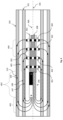
- FIG. 4 illustrates a magnetic transducer 400 with the built-in magnetic guide lens 308 as the preferred embodiments of the present invention and outlines an exemplary arrangement of the transducer that enables tubing and casing thickness imaging measurements conducted through-tubing.
- the said magnetic transducer is mounted on a nonmagnetic support structure 401 and is placed in the same measurement environment as described in FIG. 1 —that is, centralized along the axis 105 of the cylindrical inner tubing pipe 101 with an outer cylindrical casing pipe 103 placed concentrically outside of the tubing pipe 101 .
- a magnetic source 106 may provide a constant vectoral magnetic B field flux line distribution which forms the closed loops 107 , 108 , 109 , and 110 that travel through the tubing 101 and casing 103 , respectively.
- Magnetic field source 106 can be any source capable of producing a constant magnetic field, with the one example being a strong rare-earth permanent magnet.
- Four sensor ring rings 301 , 302 , 303 , and 304 are placed a certain distance away from the magnetic source 106 and are sensing casing and tubing pipe B field flux returning lines 107 , 108 , 109 , and 110 .
- a magnetic guide lens 308 with a predesigned tapered down profile, may be placed along the whole length of sensor ring rings and may be used to guide the magnetic flux distribution loops from both casing 103 and tubing 101 pipes so as to enhance ring sensitivity and SNR, as shown in FIG. 3 b , and to allow through-tubing and casing pipe imaging measurements.
- combining regions 402 , 403 , 405 , and 404 will provide the measurement aperture of the transducer 400 for the sensor rings 303 to 304 that provide thickness measurements of the casing 103 .
- Any metal pipe thickness changes corresponding to the associated spatial aperture will change the flux density distribution measurement outputs.
- the lateral spatial resolution shall be half the length of measurement aperture of the transducer 400 .
- the air gap distances for the flux loop 107 and the flux loop 108 are similar while the lengths of the traveled paths are largely different due to the spacing between the sensor ring 301 and sensor ring 302 . Therefore, thickness changes in the tubing 101 within the region 405 will generate signal measurement differences between the sensor rings 301 and 302 . Such signal measurement differences can then be used for estimating relative tubing thickness changes against the tubing nominal thickness.
- the CMS regions are 403 and 405 since flux loops 109 and 110 passing through these regions travel through the same area and same length of the pipe.
- the region 404 differences in measurements for casing 103 thickness changes result from the length differences of the paths traveled by the flux loops 109 and 110 due to the spacing between the sensor ring 303 and sensor ring 304 .
- the region 404 can be used for the casing thickness change evaluations.
- the magnetic field source 106 Since a strong magnetic field source is required to generate a strong initial B field distribution for the transducer 400 measurements and given the limited space for a downhole tool to conduct measurements inside the tubing 101 , the magnetic field source 106 with a long length is utilized to meet these requirements. As the result of this, the length of the common mode signal region 403 is longer compared to the lengths of the other regions 402 , 404 , and 405 . Consequently, measurement apertures for both tubing 101 and casing 103 become large and lateral spatial resolutions become low.
- the CMS portion from the region 403 is dominant within the total measured signals for the sensor rings 301 and 302 for the tubing 101 as well as for the sensor rings 303 and 304 for the casing 103 , which will mathematically reduce the sensitivity of measurements and the efficiency of signal channels for the signal digitization processes even though the overall SNR remains high.
- a differential measurement scheme may be needed.
- careful engineering designs for the sensor modules, spacing arrangements, and the tapered-down flux guide lens are essential.
- FIG. 5 illustrates another possible configuration of the preferred embodiments that may further enhance the measurement signal sensitivity and SNR of the differential scheme mentioned earlier for all sensor rings 301 , 302 , 303 , and 304 by adding a secondary magnetic source 501 to the left side of the magnetic source 106 .
- v T is the differential measurement output mainly corresponding to thickness changes in the tubing 101
- v C is the differential measurement output mainly corresponding to thickness changes in the casing 103
- k T and k C are weight coefficients that need to be calibrated to remove measurement signal differences from the regions 402 and 403 as the CMS for the tubing 101 and regions 402 , 403 , and 405 as the CMS for the casing 103 .
- the flux loops of the magnetic B field in the region 402 are compressed. As shown, the length of the loop 108 is compressed to be closer to the length of the loop 107 for the tubing 101 while the length of the loop 110 is compressed to be closer to the length of the loop 109 for the casing 103 in the region 402 . As the result of this field compression, the reluctance of the flux loop 107 is close to the one of flux loop 108 for the tubing 101 while reluctance of the flux loop 109 is close to the one of flux loop 110 for the casing 103 , resulting in the reduction of signal differences in the region 402 .
- the magnetic B field distribution from the magnetic source 106 is compressed by the B field distribution 502 from the secondary magnet 501 towards the right direction, as shown in the FIG. 5 .
- Such compression not only results in flux loops' length matching in the region 402 , but also forces higher density of flux lines in the region 405 for the magnetic density measurement of the tubing 101 as well as in the region 404 for the magnetic density measurement of the casing 103 .
- the differential measurement scheme in Equation (4) becomes more sensitive to thickness changes of the tubing 101 in the region 405 and of the casing 103 in the region 404 .
- the transducer aperture can be also reduced to the length of the region 405 for the tubing 101 and the length of the region 404 for the casing 103 as opposed to much longer total apertures shown in FIG. 4 .
- the combination of differential measurement scheme shown in Equation (4) and compressional magnet 501 also improves the spatial resolution in the lateral direction for thickness image measurements of both tubing 101 and casing 103 .
- FIG. 6 provides a graphical comparison of the improvements of the measurement outputs from the sensor rings from 301 to 304 for the flux density distribution along the lateral direction of the magnetic transducer apparatus without the magnetic flux guide lens and flux field compression versus the magnetic transducer apparatus with the enhanced magnetic guide lens and flux field compression thoroughly described as the preferred embodiments of the present invention.
- a comparison in measurement signal sensitivity responses of sensor rings 301 , 302 , 303 , and 304 is presented.
- the y-axis B r is the radial component of B field, traveling through tubing 101 and casing 103 pipes, which is sensed by sensor rings, and z is the distance along which the sensor rings 301 , 302 , 303 and 304 are placed.
- the measurement system noise floor line is shown as 603 , signifying a region below which the signal response from sensor rings cannot be measured due to sensor response being dominated by noise from the electronic networks connected to the sensor rings as the result of the low signal level of measurements due to the poor sensitivity.
- the FEM modeling simulation results show that for the magnetic transducer with enhanced flux guide lens and flux compression, the B r density distribution in curve 602 along the lateral direction over the area of sensor rings for given nominal values of the thicknesses for both the tubing 101 and casing 103 is much higher and more linear above the noise floor 603 than the B r density distribution response in curve 601 for the magnetic transducer without the magnetic guide lens and flux compression shown in FIG. 4 given the same pipe geometries.
- the signal measurement sensitivity curve 602 illustrates a high-sensitivity, high linearity response across all sensor rings while maintaining high positive SNR as the result of increased flux density of B R field lines passing through the sensor rings 301 , 302 , 303 and 304 due to the action of the magnetic flux guide lens 308 and compressional action of the secondary magnetic field source 501 , shown in FIG. 5 .
- the sensitivity curve response 601 illustrates a nonlinear dynamic range distribution, lack of sensitivity, and poor SNR of B R field flux distribution responses, thus rendering through-tubing casing thickness imaging measurements impossible to achieve.
- FIG. 6 also illustrates the B R field flux distribution responses corresponding to different cases of pipe thickness reductions wherein the curve 605 illustrates thickness reduction response for tubing-only pipe, the curve 606 illustrates the thickness reduction response for casing-only pipe and the curve 604 illustrates the thickness reduction response for both tubing and casing pipes.
- the sensor rings from 301 to 304 are placed in locations with predefined spacings to measure the B R field flux densities of the curves.
- the differential measurement scheme in Equation (4) is used for estimating thickness values for both pipes with the inversion of the signal measurements from the sensor rings.
- FIG. 7 illustrates various configurations of structures of the previously described magnetic flux guide lens 308 .
- the magnetic flux guide lens 308 can be shaped and sized in any suitable geometrical combination that achieves the best performance for the magnetic flux transducer that would provide the best sensitivity and SNR.
- the magnetic flux guide lens may be made in the shape of a conical cylinder with a tapered angle as in 701 , in the shape of a cylinder with a certain length and diameter as in 702 , in the shape of a polygonal shaped bar as in 703 or in the shape of a cylinder with a variable tapered profile along its length as in 704 . It shall be assumed that geometrical proportions of the said magnetic guide lens can be different from the exemplary embodiment shapes described above and can be shorter, wider, narrower or any combination thereof as dictated by application requirements.
- FIG. 8 illustrates an exemplary arrangement of sensor rings for the receiving section of the magnetic transducer apparatus as part of the present invention that senses return B R field flux densities in a radial direction arriving from tubing 101 and casing 103 pipes and provides highly sensitive tubing and casing thickness data with high azimuthal resolution.
- each individual sensor ring 801 comprises a plurality of individual magnetic flux measurement sensors 202 positioned to sense and measure the B r field flux densities.
- a plurality of sensors 202 placed a certain distance away from each other and arranged in a circular ring to enable a high degree of spatial azimuthal resolution when measuring B r field lines arriving from tubing 101 and casing 103 pipes.
- FIG. 8 illustrates an exemplary arrangement of sensor rings for the receiving section of the magnetic transducer apparatus as part of the present invention that senses return B R field flux densities in a radial direction arriving from tubing 101 and casing 103 pipes and provides highly sensitive tubing and casing thickness data with high azimuthal resolution.
- spatial azimuthal resolution of each sensor ring is a function of the number of individual sensors 202 per ring 801 with the higher number of sensors resulting in the higher spatial azimuthal resolution, shown in Equation (3.2).
- a cylindrical magnetic flux guide lens 308 is placed inside the sensor ring 801 so as to guide the B r field from tubing 101 and casing 103 pipes and increase flux density when passing through the magnetic flux measurement area of sensors 202 to enhance their sensitivity and maintain high SNR.
- Each individual sensor ring 801 may be placed a certain spacing 802 away from each other and may be placed closer or farther away in order to optimize sensitivity and dynamic range, in either the absolute or differential measurements, depending on various measurement configurations such as different diameters and thicknesses of tubing 101 and casing 103 pipes.
- FIG. 9 illustrates another exemplary arrangement of magnetic flux sensor rings as part of the present invention that allows for increased spatial azimuthal resolution of the said rings to achieve higher quality thickness imaging measurements of tubing 101 and casing 103 .
- Such measurement arrangement may then be combined with a method for processing the measured samples from the sensor rings to yield higher azimuthal resolution in the output thickness images for tubing 101 and casing 103 .
- spatial azimuthal resolution of any given ring follows Equation (3.2) which states that azimuthal resolution of a given sensor ring is a function of the number of individual sensors, with the higher number of sensors per ring resulting in higher azimuthal resolution.
- a sensor ring has a fixed diameter and surface area on which each individual sensor 202 can be placed radially with each individual sensor occupying a fraction of the said area. Therefore, only a finite number of individual magnetic flux measurement sensors 202 can be placed, which results in a certain degree of azimuthal resolution that is a function of the ring diameter, surface area of the individual sensor 202 and spacing between each of the sensors.
- the azimuthal resolution of the measured thickness images of tubing 101 and casing 103 from the sensor rings follows Equation (3.2) and expressed in angular radians.
- an exemplary arrangement and a method can be implemented that uses multiple adjacent sensor rings for sampling measurements, for example M sensor rings, with the certain identical angular offsets among the said sensor rings to enhance the azimuthal resolution.
- the angular offsets can be identical and placement of the sensor rings with the said angular offset can be arranged in sequential order. In theory, the azimuthal resolution will then be enhanced by M times after processing the measurement samples.
- Each sensor ring is placed with the angular offset determined by
- Angular ⁇ offset ⁇ in ⁇ radians 2 ⁇ ⁇ M ⁇ N ( 5. )
- the azimuthal resolution is improved by 2 times.
- sensor rings 301 and 302 shown are mounted on a support structure (body) 401 in a specific way that provides an angular offset 901 of the sensor ring 302 with respect to the sensor ring 301 .
- the sensor ring 301 is mounted in such a way that an individual magnetic flux measurement sensor 202 is placed centralized along the axis 902 , which may be referred to as the zero-degree default position axis for the sensor ring 301 .
- the sensor ring 302 may be mounted in a different way such that the individual magnetic flux measurement sensor 202 is arranged with the angular offset away, shown in 901 , from the initial position along the axis 902 and is now placed centralized along the new offset axis 903 .
- Measurements sampled from the initial position sensors mounted on sensor ring 301 and the shifted position sensors mounted on sensor ring 302 can then be processed in the digital domain using the triangular sensor scheme to extract higher combined azimuthal resolution for the output thickness image of the tubing 101 .
- the casing 103 thickness imaging azimuthal resolution can be enhanced in an identical way by offsetting the sensor ring 304 from sensor ring 303 position by a specified number of degrees and applying the triangular sensor scheme in the post-processing domain which will be described in detail below.
- FIG. 10 graphically illustrates the aforementioned method of sensor triangular sampling scheme 1000 that can be used to enhance the spatial azimuthal resolution of sensor rings in order to provide higher quality tubing and casing thickness imaging results.
- a circular receiving sensor ring R j comprises a plurality of individual sensors S 1 , S 2 , S 3 , and S 4 that are placed radially along the sensor ring and each produce unique output levels as they sense the flux density distributions of magnetic field B r .
- an adjacent circular sensor ring R j+1 that is placed with the angular offset 901 , shown in FIG. 9 , from sensor ring R j comprises a plurality of individual sensors S 1 , S 2 , S 3 , and S 4 .
- k E ⁇ ⁇ S i R j + 1 ⁇ E ⁇ ⁇ S i R j ⁇ ( 5.3 )
- FIG. 11 illustrates a block diagram of the measurement system using the magnetic transducer apparatus with the absolute or differential measurement scheme thoroughly described as the preferred embodiments of the present invention that employs triangular sample interpolation and sensor ring differential measurements necessary to obtain through-tubing and casing pipe thickness imaging measurements with high degree of azimuthal resolution.
- the magnetic field source 106 provides a constant magnetic field B which generates flux density distribution lines around the source 106 that start flowing from one pole of the magnetic field source 106 to the other.
- the flux lines enter target tubing 101 and casing 103 pipes as they follow the path of least reluctance as they travel back to the magnetic field source 106 .
- sensor rings 301 , 302 , 303 and 304 are used to sense arriving flux lines in B r from the target pipes 101 and 103 .
- Sensor rings may produce multiple analog outputs that are then fed into the analog circuit network stage 1101 which may consist of several components including, but not limited to amplifiers, resistors, and capacitors that are necessary to scale and condition the received voltage.
- the processed analog signals are then fed into the analog-to-digital converter 1102 that digitizes the analog signals into the digital signals for further signal post-processing. Digitized signals are then processed in the digital domain 1103 where interpolation and differential measurement algorithms, as shown in FIG. 10 and Equation (5.1) to (5.5), are applied in order to provide final deliverable measurement data 1104 which represents the tubing 101 and casing 103 pipe thickness images with high azimuthal spatial resolution and SNR.
- FIG. 12 displays the lab test results as thickness images from the transducer 400 , shown in FIG. 4 and FIG. 5 as the preferred embodiments of the present invention, for sensor rings 301 , 302 , 303 , and 304 , respectively.
- the case 1201 shows a pipe thickness cut 1203 as a defect on the wall of the tubing 101 while the case 1202 shows the thickness cut 1204 as a defect on the wall of the casing 103 .
- the signal responses 1205 for the tubing 101 and 1206 for the casing 103 employing the differential scheme shown in FIG. 6 and Equations (5.6) and (5.7) of signal measurements from the sensor rings 301 , 302 , 303 , and 304 are illustrated.
- Signal output images 1205 and 1206 measured and post-processed directly from the sensor rings for thickness changes for the tubing or the casing, respectively, clearly show the region of the defect, which indicates that the sensitivity and SNR of signal measurements are high enough. Therefore, the through-tubing tubing and casing thickness measurement concept using the transducer apparatus of the present invention is proven and verified with the lab experimental data.
- a magnetic sensor ring transducer apparatus and its method of signal acquisition, measurement scheme, and data processing are designed, simulated, and validated in lab tests for through tubing dual steel pipe thickness image measurements.
- the magnetic flux sensor rings comprise the sensor ring that measures the magnetic flux density distribution both in azimuthal and lateral.
- a built-in magnetic guide lens and compressional magnetic source are designed and configured in order to enhance the signal sensitivity, signal-to-noise ratio, and balance signal dynamic ranges in between the tubing and casing pipes to deliver high quality thickness images for both pipes.
- the triangle sampling scheme is utilized to improve the image resolution and borehole coverage azimuthally while the differential measurement method, incorporated with designed apparatuses for favorable enhancements of magnetic field flux distribution, is utilized to increase the image lateral resolution.
- the transducer as a logging tool is positioned inside the tubing and measures both pipe thicknesses through the tubing wall.
- the output data after the post-processing will be delivered as thickness images for tubing and casing pipes, respectively.
Landscapes
- Physics & Mathematics (AREA)
- General Physics & Mathematics (AREA)
- Life Sciences & Earth Sciences (AREA)
- Engineering & Computer Science (AREA)
- Remote Sensing (AREA)
- Condensed Matter Physics & Semiconductors (AREA)
- Geophysics (AREA)
- Geology (AREA)
- General Life Sciences & Earth Sciences (AREA)
- Environmental & Geological Engineering (AREA)
- Electromagnetism (AREA)
- Investigating Or Analyzing Materials By The Use Of Magnetic Means (AREA)
- Measurement Of Length, Angles, Or The Like Using Electric Or Magnetic Means (AREA)
Abstract
Description
Wherein A is the magnetic potential that drives a certain amount of magnetic flux Φ within the surface of S moving forward along the distance L, shown in
Where
B r,i(θ)=B 1 cos α (3.1)
Given the fixed
wherein, N is the number of
v T =V A −k T V B and v C =V C −k C V D (4)
where vT is the differential measurement output mainly corresponding to thickness changes in the
As an example, shown in
Then, the differential scheme shown in Equation (4) can be rewritten as
As illustrated in
[v T(i)]=[V 301(i)−k T V 302(i)] (5.4)
[v C(i)]=[V 303(i)−k C V 304(i)] (5.5)
for the thickness image measurement outputs [DT(i)] and [DC(i)] for the
In order for triangular sensor interpolation to work reliably under different application conditions such as variable pipe thicknesses in real measurement environments, a calibration process for kT and kC for the differential measurement scheme with a known combination of various pipe thicknesses of nominal values with no thickness reduction must be performed to derive a calibration factor to scale received readings from sensors and accurately derive interpolated readings for azimuthal resolution enhancement of sensor rings.
Claims (18)
Priority Applications (1)
| Application Number | Priority Date | Filing Date | Title |
|---|---|---|---|
| US18/084,047 US12188995B2 (en) | 2022-01-11 | 2022-12-19 | Apparatus and method for measuring thickness of tubings in downhole applications |
Applications Claiming Priority (2)
| Application Number | Priority Date | Filing Date | Title |
|---|---|---|---|
| US202263298568P | 2022-01-11 | 2022-01-11 | |
| US18/084,047 US12188995B2 (en) | 2022-01-11 | 2022-12-19 | Apparatus and method for measuring thickness of tubings in downhole applications |
Publications (2)
| Publication Number | Publication Date |
|---|---|
| US20230221385A1 US20230221385A1 (en) | 2023-07-13 |
| US12188995B2 true US12188995B2 (en) | 2025-01-07 |
Family
ID=87069432
Family Applications (1)
| Application Number | Title | Priority Date | Filing Date |
|---|---|---|---|
| US18/084,047 Active 2043-06-21 US12188995B2 (en) | 2022-01-11 | 2022-12-19 | Apparatus and method for measuring thickness of tubings in downhole applications |
Country Status (1)
| Country | Link |
|---|---|
| US (1) | US12188995B2 (en) |
Families Citing this family (1)
| Publication number | Priority date | Publication date | Assignee | Title |
|---|---|---|---|---|
| WO2024211788A1 (en) * | 2023-04-07 | 2024-10-10 | Saudi Arabian Oil Company | Electromagnetic wave focusing for concentric pipe evaluation |
Citations (2)
| Publication number | Priority date | Publication date | Assignee | Title |
|---|---|---|---|---|
| JP2001289825A (en) * | 2000-04-06 | 2001-10-19 | Osaka Gas Co Ltd | Pipe thickness measuring device by the separated eddy current method. |
| US20190004202A1 (en) * | 2017-06-28 | 2019-01-03 | Gowell International, Llc | Apparatus and Method of Azimuthal Magnetic Sensor Array for Down-Hole Applications |
-
2022
- 2022-12-19 US US18/084,047 patent/US12188995B2/en active Active
Patent Citations (2)
| Publication number | Priority date | Publication date | Assignee | Title |
|---|---|---|---|---|
| JP2001289825A (en) * | 2000-04-06 | 2001-10-19 | Osaka Gas Co Ltd | Pipe thickness measuring device by the separated eddy current method. |
| US20190004202A1 (en) * | 2017-06-28 | 2019-01-03 | Gowell International, Llc | Apparatus and Method of Azimuthal Magnetic Sensor Array for Down-Hole Applications |
Also Published As
| Publication number | Publication date |
|---|---|
| US20230221385A1 (en) | 2023-07-13 |
Similar Documents
| Publication | Publication Date | Title |
|---|---|---|
| US20200056975A1 (en) | Magnetic induction particle detection device and concentration detection method | |
| Pham et al. | Highly sensitive planar Hall magnetoresistive sensor for magnetic flux leakage pipeline inspection | |
| US5293117A (en) | Magnetic flaw detector for use with ferromagnetic small diameter tubular goods using a second magnetic field to confine a first magnetic field | |
| JP6253118B2 (en) | Differential sensor, inspection system, and method for detecting abnormality of conductive material | |
| JP4487082B1 (en) | Magnetic flux leakage flaw detection method and apparatus | |
| CN102016528B (en) | Device for measuring tension | |
| US7038444B2 (en) | System and method for in-line stress measurement by continuous Barkhausen method | |
| EP2682762A1 (en) | Current transducer for measuring an electrical current, magnetic transducer and current leakage detection system and method | |
| JPH06331602A (en) | Method and equipment for checking structural defect of long magnetic material nondestructively | |
| US8134360B2 (en) | Measurement of pipe wall thickness using magnetic flux leakage signals | |
| Suresh et al. | Development of magnetic flux leakage measuring system for detection of defect in small diameter steam generator tube | |
| JP4021321B2 (en) | Stress measurement of ferromagnetic materials | |
| CA2747053A1 (en) | Magnetic inspection device | |
| US11428668B2 (en) | Probe for eddy current non-destructive testing | |
| EP1810046B1 (en) | Sensor for measuring magnetic flux | |
| US11016060B2 (en) | Method and apparatus for evaluating damage to magnetic linear body | |
| EP3376216B1 (en) | Method for eddy-current testing of electrically conductive objects and device for realizing said method | |
| US12188995B2 (en) | Apparatus and method for measuring thickness of tubings in downhole applications | |
| Pham et al. | Planar Hall sensor for quantitative measurement of pipe wall thickness reduction based on the magnetic flux density method | |
| JP2002257789A (en) | Leakage magnetic flux detector | |
| Butin et al. | New NDE perspectives with magnetoresistance array technologies–from research to industrial applications | |
| Sharatchandra Singh et al. | Development of a high sensitive magnetic flux leakage instrument for imaging of localised flaws in small diameter ferromagnetic steel tubes | |
| RU2410538C2 (en) | Device to examine technical condition of ferromagnetic pipes | |
| Pham et al. | Accurate measurement of pipe wall reduction: High-precision instrument and minimization of uncertainties | |
| Mukherjee et al. | Phase-sensitive detection of extent of corrosion using anisotropic magnetoresistive (AMR) sensor in steel reinforcing bars (rebars) |
Legal Events
| Date | Code | Title | Description |
|---|---|---|---|
| FEPP | Fee payment procedure |
Free format text: ENTITY STATUS SET TO UNDISCOUNTED (ORIGINAL EVENT CODE: BIG.); ENTITY STATUS OF PATENT OWNER: SMALL ENTITY |
|
| FEPP | Fee payment procedure |
Free format text: ENTITY STATUS SET TO SMALL (ORIGINAL EVENT CODE: SMAL); ENTITY STATUS OF PATENT OWNER: SMALL ENTITY |
|
| STPP | Information on status: patent application and granting procedure in general |
Free format text: DOCKETED NEW CASE - READY FOR EXAMINATION |
|
| AS | Assignment |
Owner name: GOWELL INTERNATIONAL, LLC, TEXAS Free format text: ASSIGNMENT OF ASSIGNORS INTEREST;ASSIGNORS:TARASOV, ALEXANDER;ZHAO, JINSONG;RUGG, RYAN;REEL/FRAME:065440/0574 Effective date: 20230817 |
|
| STPP | Information on status: patent application and granting procedure in general |
Free format text: NON FINAL ACTION MAILED |
|
| STPP | Information on status: patent application and granting procedure in general |
Free format text: RESPONSE TO NON-FINAL OFFICE ACTION ENTERED AND FORWARDED TO EXAMINER |
|
| STPP | Information on status: patent application and granting procedure in general |
Free format text: PUBLICATIONS -- ISSUE FEE PAYMENT VERIFIED |
|
| AS | Assignment |
Owner name: GOWELL INTERNATIONAL, LLC, TEXAS Free format text: ASSIGNMENT OF ASSIGNORS INTEREST;ASSIGNORS:RUGG, RYAN;ZHAO, JINSONG;TARASOV, ALEXANDER;REEL/FRAME:069466/0534 Effective date: 20241112 |
|
| STCF | Information on status: patent grant |
Free format text: PATENTED CASE |