US12186917B2 - Method and apparatus for calibrating ophthalmic lens grippers - Google Patents
Method and apparatus for calibrating ophthalmic lens grippers Download PDFInfo
- Publication number
- US12186917B2 US12186917B2 US17/229,006 US202117229006A US12186917B2 US 12186917 B2 US12186917 B2 US 12186917B2 US 202117229006 A US202117229006 A US 202117229006A US 12186917 B2 US12186917 B2 US 12186917B2
- Authority
- US
- United States
- Prior art keywords
- gripper
- lens
- tip
- master
- directional
- Prior art date
- Legal status (The legal status is an assumption and is not a legal conclusion. Google has not performed a legal analysis and makes no representation as to the accuracy of the status listed.)
- Active, expires
Links
- 238000000034 method Methods 0.000 title claims abstract description 41
- 238000004519 manufacturing process Methods 0.000 claims abstract description 41
- 238000007689 inspection Methods 0.000 claims description 14
- 238000005259 measurement Methods 0.000 claims description 7
- FGUUSXIOTUKUDN-IBGZPJMESA-N C1(=CC=CC=C1)N1C2=C(NC([C@H](C1)NC=1OC(=NN=1)C1=CC=CC=C1)=O)C=CC=C2 Chemical compound C1(=CC=CC=C1)N1C2=C(NC([C@H](C1)NC=1OC(=NN=1)C1=CC=CC=C1)=O)C=CC=C2 FGUUSXIOTUKUDN-IBGZPJMESA-N 0.000 claims description 4
- 230000008878 coupling Effects 0.000 description 2
- 238000010168 coupling process Methods 0.000 description 2
- 238000005859 coupling reaction Methods 0.000 description 2
- 238000001514 detection method Methods 0.000 description 2
- 238000010586 diagram Methods 0.000 description 2
- 230000003287 optical effect Effects 0.000 description 2
- 238000009516 primary packaging Methods 0.000 description 2
- 230000001419 dependent effect Effects 0.000 description 1
- 239000007788 liquid Substances 0.000 description 1
- 239000002184 metal Substances 0.000 description 1
- 238000012986 modification Methods 0.000 description 1
- 230000004048 modification Effects 0.000 description 1
Images


Classifications
-
- G—PHYSICS
- G05—CONTROLLING; REGULATING
- G05B—CONTROL OR REGULATING SYSTEMS IN GENERAL; FUNCTIONAL ELEMENTS OF SUCH SYSTEMS; MONITORING OR TESTING ARRANGEMENTS FOR SUCH SYSTEMS OR ELEMENTS
- G05B19/00—Programme-control systems
- G05B19/02—Programme-control systems electric
- G05B19/18—Numerical control [NC], i.e. automatically operating machines, in particular machine tools, e.g. in a manufacturing environment, so as to execute positioning, movement or co-ordinated operations by means of programme data in numerical form
- G05B19/401—Numerical control [NC], i.e. automatically operating machines, in particular machine tools, e.g. in a manufacturing environment, so as to execute positioning, movement or co-ordinated operations by means of programme data in numerical form characterised by control arrangements for measuring, e.g. calibration and initialisation, measuring workpiece for machining purposes
-
- B—PERFORMING OPERATIONS; TRANSPORTING
- B25—HAND TOOLS; PORTABLE POWER-DRIVEN TOOLS; MANIPULATORS
- B25J—MANIPULATORS; CHAMBERS PROVIDED WITH MANIPULATION DEVICES
- B25J9/00—Programme-controlled manipulators
- B25J9/16—Programme controls
- B25J9/1679—Programme controls characterised by the tasks executed
- B25J9/1692—Calibration of manipulator
-
- B—PERFORMING OPERATIONS; TRANSPORTING
- B25—HAND TOOLS; PORTABLE POWER-DRIVEN TOOLS; MANIPULATORS
- B25J—MANIPULATORS; CHAMBERS PROVIDED WITH MANIPULATION DEVICES
- B25J15/00—Gripping heads and other end effectors
- B25J15/06—Gripping heads and other end effectors with vacuum or magnetic holding means
- B25J15/0616—Gripping heads and other end effectors with vacuum or magnetic holding means with vacuum
-
- B—PERFORMING OPERATIONS; TRANSPORTING
- B29—WORKING OF PLASTICS; WORKING OF SUBSTANCES IN A PLASTIC STATE IN GENERAL
- B29D—PRODUCING PARTICULAR ARTICLES FROM PLASTICS OR FROM SUBSTANCES IN A PLASTIC STATE
- B29D11/00—Producing optical elements, e.g. lenses or prisms
- B29D11/00009—Production of simple or compound lenses
- B29D11/00038—Production of contact lenses
- B29D11/00125—Auxiliary operations, e.g. removing oxygen from the mould, conveying moulds from a storage to the production line in an inert atmosphere
- B29D11/00173—Conveying moulds
- B29D11/00182—Conveying moulds using carrier plates
-
- B—PERFORMING OPERATIONS; TRANSPORTING
- B29—WORKING OF PLASTICS; WORKING OF SUBSTANCES IN A PLASTIC STATE IN GENERAL
- B29D—PRODUCING PARTICULAR ARTICLES FROM PLASTICS OR FROM SUBSTANCES IN A PLASTIC STATE
- B29D11/00—Producing optical elements, e.g. lenses or prisms
- B29D11/00951—Measuring, controlling or regulating
-
- B—PERFORMING OPERATIONS; TRANSPORTING
- B65—CONVEYING; PACKING; STORING; HANDLING THIN OR FILAMENTARY MATERIAL
- B65G—TRANSPORT OR STORAGE DEVICES, e.g. CONVEYORS FOR LOADING OR TIPPING, SHOP CONVEYOR SYSTEMS OR PNEUMATIC TUBE CONVEYORS
- B65G47/00—Article or material-handling devices associated with conveyors; Methods employing such devices
- B65G47/74—Feeding, transfer, or discharging devices of particular kinds or types
- B65G47/90—Devices for picking-up and depositing articles or materials
- B65G47/91—Devices for picking-up and depositing articles or materials incorporating pneumatic, e.g. suction, grippers
-
- G—PHYSICS
- G01—MEASURING; TESTING
- G01B—MEASURING LENGTH, THICKNESS OR SIMILAR LINEAR DIMENSIONS; MEASURING ANGLES; MEASURING AREAS; MEASURING IRREGULARITIES OF SURFACES OR CONTOURS
- G01B11/00—Measuring arrangements characterised by the use of optical techniques
- G01B11/002—Measuring arrangements characterised by the use of optical techniques for measuring two or more coordinates
-
- G—PHYSICS
- G01—MEASURING; TESTING
- G01B—MEASURING LENGTH, THICKNESS OR SIMILAR LINEAR DIMENSIONS; MEASURING ANGLES; MEASURING AREAS; MEASURING IRREGULARITIES OF SURFACES OR CONTOURS
- G01B21/00—Measuring arrangements or details thereof, where the measuring technique is not covered by the other groups of this subclass, unspecified or not relevant
- G01B21/02—Measuring arrangements or details thereof, where the measuring technique is not covered by the other groups of this subclass, unspecified or not relevant for measuring length, width, or thickness
- G01B21/04—Measuring arrangements or details thereof, where the measuring technique is not covered by the other groups of this subclass, unspecified or not relevant for measuring length, width, or thickness by measuring coordinates of points
- G01B21/042—Calibration or calibration artifacts
-
- B—PERFORMING OPERATIONS; TRANSPORTING
- B29—WORKING OF PLASTICS; WORKING OF SUBSTANCES IN A PLASTIC STATE IN GENERAL
- B29D—PRODUCING PARTICULAR ARTICLES FROM PLASTICS OR FROM SUBSTANCES IN A PLASTIC STATE
- B29D11/00—Producing optical elements, e.g. lenses or prisms
- B29D11/00009—Production of simple or compound lenses
- B29D11/00038—Production of contact lenses
- B29D11/00125—Auxiliary operations, e.g. removing oxygen from the mould, conveying moulds from a storage to the production line in an inert atmosphere
- B29D11/0023—Transferring contact lenses
- B29D11/0024—Transferring contact lenses using a vacuum suction gripper
Definitions
- the present invention relates to a method and apparatus for calibrating lens grippers used in the transport of ophthalmic lenses, such as contact lenses.
- the calibration method and apparatus are particularly useful for enabling rapid replacement of lens grippers with minimal production line down time.
- grippers may be used to remove contact lenses from mold halves, to place into and remove contact lenses from inspection cuvettes and treatment containers, to re-invert contact lenses that are inverted, and to place contact lenses in their final destination in the primary packaging container (blister pack).
- primary packaging container blister pack
- grippers for contact lenses are known, by way of example, as from PCT publications WO2011/026868, WO2010/020623, and WO2015/036431, and generally are movable or have a movable member capable of moving downwardly (that is, vertically in the Z-direction) into whichever type of receptacle the contact lenses resides so as to engage the contact lens, and thereafter capable of moving back upwardly to remove the contact lens from that receptacle for placement of the contact lens into the next receptacle in the manufacturing line.
- a method for calibrating lens grippers for ophthalmic lenses, in particular contact lenses, prior to use of the lens grippers in a lens manufacturing line is suggested.
- the method includes the steps of:
- the predetermined position of the tip of the lens gripper is preferably within about 300 microns of the measured Z-directional position of the tip of the master gripper; that is to say, the predetermined position of the tip of the lens gripper may be about 300 microns higher or lower than the measured Z-directional position of the master gripper.
- the remote gripper calibration tool may also include an X-directional position sensor and a Y-directional position sensor, and may in step d) of the method further include measuring the X- and Y-directional positions of the master gripper with the respective X- and Y-directional sensors, and may in step f) further include measuring the X- and Y-directional positions of the lens gripper with the respective X- and Y-directional position sensors to determine proper orientation and centration of the lens gripper.
- the lens gripper may be properly centered if the measured X- and Y-directional positions of the lens gripper are independently within 300 microns (micrometers, ⁇ m) of the measured X- and Y-directional positions of the master gripper.
- the remote gripper calibration tool may include a vacuum connector and a pneumatic pressure connector, and in step f) may further include connecting the lens gripper to the vacuum connector and the pneumatic pressure connector to test proper vacuum and pressure function.
- the method further includes providing a lens receptacle carrier plate and mounting an adapter thereon, the adapter including a plurality of raised target studs having an upper surface, and in a lens manufacturing line having a lens receptacle transport system and a gripper mounting plate including a plurality of lens gripper mounting positions.
- the method further includes the steps of mounting the lens receptacle carrier plate onto the lens receptacle transport system, mounting the master gripper to the gripper mounting plate at at least a first and second of the plurality of lens gripper mounting positions, measuring the distance between the tip of the master gripper and the upper surface of the raised target studs, and adjusting the Z-directional position of the tip of the master gripper by adjusting the gripper mounting plate to achieve a desired pre-determined distance between the upper surface of the raised target studs and the tip of the master gripper, at at least the first and second of the plurality of lens gripper mounting positions.
- the desired predetermined distance between the upper surface of the raised target studs and the tip of the master gripper may be measured using a feeler gauge or a laser measurement device. In some further aspects, the desired predetermined distance between the upper surface of the raised target studs and the tip of the master gripper is from about 400 microns to about 1000 microns, and particularly about 700 microns.
- the lens receptacle carrier plate may be configured for mounting lens inspection cuvettes thereon instead of the adapter including the raised target studs, each lens inspection cuvette having a cuvette bottom for an ophthalmic lens to rest on, and the method further includes mounting the lens inspection cuvettes to the receptacle carrier plate with the cuvette bottoms arranged at a level corresponding to a level of the upper surfaces of the raised target studs.
- the lens receptacle carrier plate may be configured to carry lens mold halves arranged thereon instead of the adapter including the raised target studs, each lens mold half including a surface to be gripped by the lens gripper, and wherein the method further includes arranging the lens mold halves on the lens receptacle carrier plate with the surfaces to be gripped arranged at a level corresponding to a level of the upper surfaces of the raised target studs.
- the lens receptacle carrier plate may be configured to carry lens blister packages arranged thereon instead of the adapter including the raised target studs, each lens blister package including a surface to be gripped by the lens gripper, and wherein the method further includes arranging the lens blister packages with the surfaces to be gripped arranged at a level corresponding to a level of the upper surfaces of the raised target studs.
- an apparatus for calibrating lens grippers for ophthalmic lenses, preferably contact lenses, prior to use of the lens grippers in a lens manufacturing line including:
- the remote gripper calibration tool may further include an X-directional position sensor and a Y-directional position sensor, the X-directional position sensor and the Y-directional position sensor being configured and arranged to measure the X-directional and Y-directional positions of the master gripper and of the lens gripper.
- the gripper calibration tool may further include a vacuum connector and a pneumatic pressure connector configured and arranged to test proper vacuum and pressure function of a lens gripper to be calibrated.
- the method and apparatus according to the invention have a plurality of advantages.
- One very important advantage is that a plurality of lens grippers can be calibrated off-line and remote from the manufacturing line at the remote gripper calibration tool, and can be stored in this calibrated state so as to be readily available at the time a lens gripper needs to be replaced in the manufacturing line. Replacement of the lens gripper in the manufacturing line can then be performed simply by unmounting the lens gripper to be replaced from the manufacturing line and by subsequently mounting a stored calibrated lens gripper to the manufacturing line. No calibration of the stored lens gripper needs to be performed on the manufacturing line anymore, thus greatly reducing the down time of the manufacturing line during gripper replacement.
- the calibrated lens gripper is not only calibrated with respect to the Z-directional position but also with respect to the X- and Y-directional positions, so that the calibrated lens gripper is centered, not inclined relative to the Z-direction, and is exactly calibrated as to the distance from the surface of the receptacle on which the ophthalmic lens rests and from which it is to be extracted.
- a particular station of a manufacturing line can be easily calibrated using the master gripper mounted to the gripper mounting plate of that station of the manufacturing line on one hand, and the lens receptacle carrier plate mounted to the (levelled) transport system of the manufacturing line carrying the adapter comprising the plurality of raised target studs having an upper surface on the other hand.
- Calibration of the station needs to be performed only once, and may be performed by adjusting the gripper mounting plate with the master gripper mounted to the gripper mounting plate at a first lens gripper mounting position. Adjustment is then performed such that the tip of the master gripper has a desired predetermined distance (in the range of, for example, 400 to 1000 microns. i.e.
- micrometers or ‘ ⁇ m’, particularly about 700 microns) from the upper surface of the raised target stud The position of this upper surface of the raised target stud corresponds to the position of the surface the ophthalmic lens rests on in the lens receptacle. Subsequently, the same adjustment is performed with the master gripper mounted to the gripper mounting plate at a second lens gripper mounting position.
- these first and second lens gripper mounting positions can be the first and last gripper mounting positions of the plurality of gripper mounting positions of a gripper mounting plate, although this is not mandatory.
- the precise adjustment of the master gripper relative to the upper surface of the raised target stud may be reliably performed using a feeler gauge or any suitable optical measurement device, for example a laser measurement device.
- lens grippers may be used in a lens inspection station of a manufacturing line in which the ophthalmic lenses, e.g. contact lenses, are inspected in a liquid contained in an inspection cuvette and are subsequently removed from this inspection cuvette and placed into a primary packaging shell (e.g. the shell of a blister pack), they may generally be used in any station of a manufacturing line in which ophthalmic lenses are transferred from one receptacle to another receptacle.
- a primary packaging shell e.g. the shell of a blister pack
- the invention provides for a very easy quick-change method and apparatus significantly reducing the overall down time of a manufacturing line in case a lens gripper needs to be replaced.
- FIG. 1 illustrates an exemplary aspect of the general setup of the remote gripper calibration tool according to the present invention, including detail area A;
- FIG. 2 illustrates the detail area A of FIG. 1 ;
- FIG. 3 illustrates a side view of the master gripper
- FIG. 4 illustrates a perspective view of the master gripper
- FIG. 5 illustrates a perspective view of a lens gripper
- FIG. 6 illustrates a side view of a lens gripper mounted to the remote gripper calibration tool
- FIG. 7 illustrates a perspective view of a lens receptacle carrier plate with mounted adapter
- FIG. 8 illustrates the carrier plate of FIG. 7 in edge view
- FIG. 9 illustrates the master gripper in use with the lens receptacle carrier plate shown in FIGS. 7 - 8 , including detail area B;
- FIG. 10 illustrates the lens receptacle carrier plate as it would be used in a manufacturing line
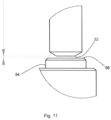
- FIG. 11 illustrates the detail area B of FIG. 9 .
- FIG. 1 illustrates the remote gripper calibration tool 1 which includes an assembly plate 10 to which a master gripper 30 is mounted (the master gripper 30 is shown in more detail in FIGS. 3 - 4 ).
- the remote gripper calibration tool 1 also includes at least a Z-directional position sensor 12 (see detail A as shown in FIG. 2 ).
- the Z-directional position sensor 12 is desirably a non-contact sensor and may be, for example, a laser detection system capable of determining position based on the amount of light occluded, which is fixedly mounted to the remote gripper calibration tool 1 .
- the remote gripper calibration tool 1 may also desirably include an X-directional position sensor 14 and a Y-directional position sensor 16 as shown in FIG. 2 , which like Z-directional position sensor 12 may be non-contact sensors such as the mentioned laser detection system.
- FIG. 2 also includes a positional diagram illustrating the Z-direction (up/down, i.e., vertical), Y-direction (left-right horizontal as the figure is viewed) and X-direction (into and out of the diagram as the figure is viewed).
- FIGS. 3 - 4 illustrate the master gripper 30 in more detail, including the tip 32 of the master gripper.
- the master gripper 30 has a length extension terminating in the tip 32 so as to match a predetermined desired final extension length of a lens gripper which is to be calibrated.
- the master gripper 30 also has mounting portions 34 , 36 which lie flush against the assembly plate 10 when the master gripper 30 is mounted thereto, and contain fastening elements 38 which may be for example a bolt or captive screw (additional fastening elements of mounting portions 34 , 36 are not shown).
- the mounting portions and fastening elements of the master gripper 30 as well as centering bolts (not shown) projecting from the surface of the mounting portions 34 , 36 towards the assembly plate 10 and fitting into corresponding centering holes in the assembly plate 10 are configured to match those of an actual lens gripper (to make sure the master gripper 30 and the lens grippers to be calibrated are reproducibly mounted to the assembly plate).
- the master gripper 30 is shown mounted to the assembly plate 10 , with the tip 32 of the master gripper 30 extending into the portion of the remote gripper calibration tool 1 including the Z-directional position sensor 12 to measure the Z-directional position of the tip 32 of the master gripper 30 .
- X- and Y-directional position sensors 14 and 16 may also be provided and if so, are used to measure or determine the X- and Y-position of the tip 32 of the master gripper 30 .
- the master gripper 30 is unmounted from the remote gripper calibration tool 1 .
- a lens gripper 40 is shown in FIG. 5 .
- the lens gripper 40 has a tip 42 which engages and picks up a contact lens from a receptacle.
- Lens gripper 40 also includes a handle 44 for assistance in managing the mass of the lens gripper 40 during mounting and unmounting operations.
- the lens gripper 40 is set with its tip 42 in the lowermost position or its final extension length.
- the tip 42 of the lens gripper 40 is raised and lowered along the pneumatic cylinder 46 to remove a contact lens from its receptacle; that is, in its lowermost position the tip 42 of the lens gripper 40 inserts into a receptacle to collect the lens then is raised along the pneumatic cylinder 46 to extract the lens from the receptacle.
- the lens gripper 40 to be calibrated is mounted to the assembly plate 10 of the remote gripper calibration tool 1 . While not shown in FIG. 6 , as mentioned above the master gripper 30 and the lens gripper 40 generally have the same type of mounting portions and fastening elements, to achieve the same fit to assembly plate 10 .
- the tip 42 of the lens gripper 40 matches the predetermined desired final extension length, which as mentioned above was determined using the master gripper 30 , or is within an acceptable distance of the determined Z-directional position of the tip 32 of the master gripper 30 .
- the tip 42 of the lens gripper 40 should be within about 300 microns (plus or minus) of the determined Z-directional position of the tip 32 of the master gripper 30 . If the tip 42 of the lens gripper 40 is not within an acceptable Z-directional distance, the final extension length of the tip 42 of the lens gripper 40 is adjusted to match the predetermined final extension length or to be within the acceptable distance.
- the X-directional position sensor 14 and a Y-directional position sensor 16 it can be determined whether the tip 42 of the lens gripper 40 matches (or is within an acceptable distance of) the X- and Y-position information collected when the master gripper 30 was mounted to the assembly plate 10 of the remote gripper calibration tool 1 . If the tip 42 does not match the X- and/or Y-position information collected using the master gripper 30 , e.g. tip 42 is not centered or is tilted at an angle from vertical, this could indicate that the lens gripper 40 is not fully mounted to the assembly plate 10 or in need of additional adjustment, or that it had been improperly manufactured, and that another lens gripper need be selected. Once a given gripper has undergone the calibration process, it can be stored away until it is needed to rapidly replace another lens gripper on the lens manufacturing line.
- the remote gripper calibration tool 1 may be provided with additional features, such as a vacuum connector 20 and a pneumatic pressure connector 22 which may be connected to the lens gripper 40 via the respective vacuum coupling 24 and pneumatic pressure coupling 26 of the lens gripper 40 , and used to test for proper vacuum and pressure function of the lens gripper 40 .
- the remote gripper calibration tool 1 may be provided with one or more electrical connectors (not shown) which may be connected to corresponding electrical connectors of the lens gripper 40 to test proper function of the electrical connectors for operating the control valves of the lens gripper 40 enabling the supply of vacuum or pressure.
- FIGS. 7 - 11 illustrate still a further aspect of the invention.
- FIGS. 7 - 8 show a lens receptacle carrier plate 50 in perspective and edge-view, respectively.
- the lens receptacle carrier plate 50 is part of a lens receptacle transport system and may be a plate for carrying various types of lens-containing receptacles during contact lens manufacturing.
- the lens receptacle carrier plate 50 may be configured to and used to carry lens inspection cuvettes, lens mold halves, lens blister packages, or other receptacles used to hold contact lenses at various points in a manufacturing line.
- no lens receptacles are placed on the lens receptacle carrier plate 50 and instead an adapter 52 is mounted thereon.
- the adapter 52 includes a plurality of raised target studs 54 with an upper surface 56 , as shown in FIGS. 7 - 8 .
- the master gripper 30 is utilized temporarily on the actual lens manufacturing line. It should be noted that in the practice of this further aspect of the invention, it does not matter whether the master gripper 30 is first mounted to the assembly plate 10 of the remote gripper calibration tool 1 to have the positioning of the tip 32 of the master gripper 30 determined, or whether the master gripper 30 is first utilized in this further aspect on the lens manufacturing line. In use, the master gripper 30 is mounted to a gripper mounting plate on the lens manufacturing line. Generally such a gripper mounting plate includes a plurality of positions for lens grippers, for example seven, eight, ten, twelve, fourteen, sixteen, eighteen, twenty or more. The master gripper 30 is mounted to a first position on the gripper mounting plate and in the practice of this further aspect of the invention, the lens receptacle carrier plate 50 including the adapter 52 is transported in the manufacturing line below the master gripper 30 .
- FIG. 9 This is shown in FIG. 9 with the master gripper 30 positioned above the lens receptacle carrier plate 50 and in particular the tip 32 of the master gripper 30 is position directly above the upper surface 56 of one of the target studs 54 .
- detail B of FIG. 9 as shown in FIG. 11 , it can be seen that a small gap or distance exists between the tip 32 of the master gripper 30 and the upper surface 56 of the target stud 54 (the gap as indicated by the converging arrows), such that the tip 32 of the master gripper 30 does not contact the upper surface 56 of the target stud 54 .
- This distance corresponds to a desired predetermined distance and is configured to be small enough to permit a lens gripper to acquire the contact lens from a receptacle, but not so small that the tip 42 of the lens gripper presses the lens against the bottom of the receptacle, which could cause damage to the contact lens.
- a suitable gap or distance between the tip 32 of the master gripper 30 and the upper surface 56 of the target stud 54 may be between about 400 microns and about 1000 microns, and may particularly be about 700 microns.
- the distance may be measured and set using known tools such as finely machined metal feeler or gapping gauge, or by use of laser measurement devices or other optical measurement devices such as are known to those of skill in the art.
- the gripper mounting plate may be adjusted upwards or downwards to correct the distance. Then, the master gripper 30 is mounted to at least one, second position on the gripper mounting plate (or a second essentially identical master gripper 30 is used) and the process of measuring the gap or distance, and adjusting the gripper mounting plate if necessary, is repeated to ensure that the distance is the same across the gripper mounting plate as between the tip 32 of the master gripper 30 and the upper surface 56 of the target stud 54 for each position so tested. Normally the positions for mounting the master gripper 30 to the gripper mounting plate will be the first and last of the plurality of positions, but this is not required as long as sufficient distance exists between positions to ensure reliable result.
- FIG. 10 shows the lens gripper 40 mounted on the gripper mounting plate and the lens receptacle carrier plate 50 holding lens inspection cuvette 60 .
- the tip of the lens gripper 40 is not visible because it is inserted inside the lens inspection cuvette 60 in order to grip the contact lenses (not shown).
- FIGS. 9 - 10 are on the same level and it can be seen that in the case of the lens receptacle carrier plate 50 carrying the lens inspection cuvettes 60 , the cuvettes are configured and mounted such that the cuvette bottoms are arranged to be at a level that corresponds to the level of the upper surfaces 56 of the target studs 54 when the adapter plate 52 was mounted to the lens receptacle carrier plate 50 .
- each of the mold halves has a surface holding a contact lens to be gripped by a lens gripper, and so the mold halves are arranged on the lens receptacle carrier plate 50 with the surface arranged to be at a level that corresponds to the level of the upper surfaces 56 of the target studs 54 when the adapter plate 52 was mounted to the lens receptacle carrier plate 50 .
- each of the blister packages has a surface holding a contact lens to be gripped by a lens gripper (or a surface upon which a contact lens is to be deposited by a lens gripper), and so the blister packages are arranged on the lens receptacle carrier plate 50 with such surface arranged to be at a level that corresponds to the level of the upper surfaces 56 of the target studs 54 when the adapter plate 52 was mounted to the lens receptacle carrier plate 50 .
Landscapes
- Engineering & Computer Science (AREA)
- Mechanical Engineering (AREA)
- Manufacturing & Machinery (AREA)
- Health & Medical Sciences (AREA)
- Ophthalmology & Optometry (AREA)
- Physics & Mathematics (AREA)
- General Physics & Mathematics (AREA)
- Robotics (AREA)
- Human Computer Interaction (AREA)
- Automation & Control Theory (AREA)
- Eyeglasses (AREA)
Abstract
Description
-
- a) providing a remote gripper calibration tool including an assembly plate and a Z-directional position sensor;
- b) providing a master gripper having a length dimension terminating in a tip, the length dimension being predetermined to match a desired final extension length of a lens gripper;
- c) mounting the master gripper to the assembly plate;
- d) measuring the Z-directional position of the tip of the master gripper with the Z-directional position sensor;
- e) unmounting the master gripper from the assembly plate;
- f) mounting a lens gripper to be calibrated to the assembly plate, the lens gripper having a tip, and calibrating the lens gripper by adjusting the final extension length of the tip of the lens gripper to a predetermined position relative to the measured Z-directional position of the tip of the master gripper.
-
- a remote gripper calibration tool having an assembly plate and a Z-directional position sensor configured to measure a predetermined range of Z-directional positions;
- a master gripper configured to be mounted to the assembly plate, the master gripper having a length dimension terminating in a tip, the length dimension being predetermined to match a desired final extension length of a lens gripper to be calibrated, wherein the Z-directional position sensor is arranged relative to the assembly plate at a location at which the tip of the master gripper mounted to the assembly plate is arranged at a Z-directional tip position within the predetermined range of Z-directional positions of the Z-directional position sensor, the Z-directional tip position being spaced by at least 300 microns from an upper end as well as from a lower end of the predetermined range of Z-directional positions.
Claims (14)
Priority Applications (1)
| Application Number | Priority Date | Filing Date | Title |
|---|---|---|---|
| US17/229,006 US12186917B2 (en) | 2020-04-16 | 2021-04-13 | Method and apparatus for calibrating ophthalmic lens grippers |
Applications Claiming Priority (2)
| Application Number | Priority Date | Filing Date | Title |
|---|---|---|---|
| US202063011083P | 2020-04-16 | 2020-04-16 | |
| US17/229,006 US12186917B2 (en) | 2020-04-16 | 2021-04-13 | Method and apparatus for calibrating ophthalmic lens grippers |
Publications (2)
| Publication Number | Publication Date |
|---|---|
| US20210323162A1 US20210323162A1 (en) | 2021-10-21 |
| US12186917B2 true US12186917B2 (en) | 2025-01-07 |
Family
ID=75977777
Family Applications (1)
| Application Number | Title | Priority Date | Filing Date |
|---|---|---|---|
| US17/229,006 Active 2043-11-09 US12186917B2 (en) | 2020-04-16 | 2021-04-13 | Method and apparatus for calibrating ophthalmic lens grippers |
Country Status (4)
| Country | Link |
|---|---|
| US (1) | US12186917B2 (en) |
| EP (1) | EP4136512A1 (en) |
| TW (1) | TWI785564B (en) |
| WO (1) | WO2021209896A1 (en) |
Families Citing this family (4)
| Publication number | Priority date | Publication date | Assignee | Title |
|---|---|---|---|---|
| USD1054895S1 (en) * | 2020-02-24 | 2024-12-24 | Autel Intelligent Technology Corp., Ltd. | Vehicle calibration device |
| USD1070623S1 (en) * | 2020-07-10 | 2025-04-15 | Autel Intelligent Technology Corp., Ltd. | Calibration support device |
| CN113275155B (en) * | 2021-04-26 | 2022-07-12 | 苏州科韵激光科技有限公司 | Nozzle length adjusting device and method |
| CN116423479B (en) * | 2023-05-23 | 2023-10-24 | 深圳富山科技有限公司 | Robot auxiliary material taking secondary positioning device |
Citations (9)
| Publication number | Priority date | Publication date | Assignee | Title |
|---|---|---|---|---|
| EP0131743B1 (en) | 1983-06-16 | 1991-09-04 | Pilkington Visioncare, Inc. | Calibration gauge for computer-controlled lens generator or the like |
| US6438448B1 (en) * | 2000-02-08 | 2002-08-20 | Storage Technology Corporation | Self aligning robotic arm calibration apparatus |
| WO2003016855A1 (en) | 2001-08-17 | 2003-02-27 | Novartis Ag | Cuvette for lens inspection |
| EP1136241B1 (en) | 2000-03-16 | 2006-06-21 | Novartis AG | Apparatus for the removal of contact lenses |
| WO2010020623A1 (en) | 2008-08-20 | 2010-02-25 | Novartis Ag | Apparatus for removing an ophthalmic lens from a mold half |
| WO2011026868A1 (en) | 2009-09-04 | 2011-03-10 | Novartis Ag | Gripper for a contact lens and process for transporting a contact lens |
| WO2015036431A1 (en) | 2013-09-11 | 2015-03-19 | Novartis Ag | Gripper for a contact lens and process for transporting a contact lens |
| US20150138540A1 (en) | 2012-05-10 | 2015-05-21 | Menicon Singapore Pte Ltd. | Systems and methods for the inspection of contact lenses |
| US10518265B2 (en) | 2011-09-25 | 2019-12-31 | Theranos Ip Company, Llc | Systems and methods for fluid handling |
-
2021
- 2021-04-13 US US17/229,006 patent/US12186917B2/en active Active
- 2021-04-13 WO PCT/IB2021/053040 patent/WO2021209896A1/en not_active Ceased
- 2021-04-13 EP EP21726452.2A patent/EP4136512A1/en active Pending
- 2021-04-15 TW TW110113530A patent/TWI785564B/en active
Patent Citations (13)
| Publication number | Priority date | Publication date | Assignee | Title |
|---|---|---|---|---|
| EP0131743B1 (en) | 1983-06-16 | 1991-09-04 | Pilkington Visioncare, Inc. | Calibration gauge for computer-controlled lens generator or the like |
| US6438448B1 (en) * | 2000-02-08 | 2002-08-20 | Storage Technology Corporation | Self aligning robotic arm calibration apparatus |
| EP1136241B1 (en) | 2000-03-16 | 2006-06-21 | Novartis AG | Apparatus for the removal of contact lenses |
| WO2003016855A1 (en) | 2001-08-17 | 2003-02-27 | Novartis Ag | Cuvette for lens inspection |
| TW565686B (en) | 2001-08-17 | 2003-12-11 | Novartis Ag | Cuvette for lens inspection |
| US9254616B2 (en) * | 2008-08-20 | 2016-02-09 | Novartis Ag | Apparatus for removing an ophthalmic lens from a mold half |
| WO2010020623A1 (en) | 2008-08-20 | 2010-02-25 | Novartis Ag | Apparatus for removing an ophthalmic lens from a mold half |
| US20160167322A1 (en) * | 2008-08-20 | 2016-06-16 | Novartis Ag | Apparatus for removing an ophthalmic lens from a mold half |
| US9796145B2 (en) * | 2008-08-20 | 2017-10-24 | Novartis Ag | Apparatus for removing an ophthalmic lens from a mold half |
| WO2011026868A1 (en) | 2009-09-04 | 2011-03-10 | Novartis Ag | Gripper for a contact lens and process for transporting a contact lens |
| US10518265B2 (en) | 2011-09-25 | 2019-12-31 | Theranos Ip Company, Llc | Systems and methods for fluid handling |
| US20150138540A1 (en) | 2012-05-10 | 2015-05-21 | Menicon Singapore Pte Ltd. | Systems and methods for the inspection of contact lenses |
| WO2015036431A1 (en) | 2013-09-11 | 2015-03-19 | Novartis Ag | Gripper for a contact lens and process for transporting a contact lens |
Also Published As
| Publication number | Publication date |
|---|---|
| TWI785564B (en) | 2022-12-01 |
| TW202140249A (en) | 2021-11-01 |
| EP4136512A1 (en) | 2023-02-22 |
| US20210323162A1 (en) | 2021-10-21 |
| WO2021209896A1 (en) | 2021-10-21 |
Similar Documents
| Publication | Publication Date | Title |
|---|---|---|
| US12186917B2 (en) | Method and apparatus for calibrating ophthalmic lens grippers | |
| KR101748583B1 (en) | Probe pin bonding device | |
| CN112534555A (en) | Wireless substrate class teaching sensor for semiconductor processing | |
| CN102009235B (en) | Method for positioning workpiece and electrode in die discharge process | |
| KR20180049512A (en) | Manufacturing system of battery cell | |
| CN105050744B (en) | Production line for the production of sheet-metal shaped parts, comprising at least one measuring device for checking the manufactured sheet-metal shaped parts | |
| KR102297846B1 (en) | Die bonding apparatus and manufacturing method of semiconductor device | |
| US11806794B2 (en) | Processing device and processing method | |
| US10232511B2 (en) | Method for calibrating a measuring apparatus for measuring body parts and other workpieces, and measuring apparatus suitable for carrying out the method | |
| KR101543317B1 (en) | Bonding Member And Semiconductor Chip Bonding Apparatus Having the Same | |
| JP2000292313A (en) | Method for holding spectacle lens, holding device, and inspection method and inspection device using the same | |
| KR20080112383A (en) | Method and apparatus for contrasting defect distribution patterns | |
| CN115881570A (en) | Method and system for detecting wafer edge topography | |
| JP2010188437A (en) | Distortion detecting method and automatic replacing system for robot hand | |
| US9659798B2 (en) | System and method for producing devices including a semiconductor part and a non-semiconductor part | |
| US11538702B2 (en) | Apparatus for monitoring an exchanging process of a semiconductor part and a method for the same | |
| KR101148086B1 (en) | Inspection apparatus of drive shaft for vehicle window | |
| KR20240009653A (en) | Probe Bonding Device and Probe Bonding Method Using the Same | |
| KR20120030841A (en) | Wafer marking device, marking position inspecting member and controlling method of wafer marking device | |
| CN113654594A (en) | Special on-line measuring machine of piston | |
| CN219123192U (en) | Thimble height calibration jig and separating mechanism | |
| CN104647133A (en) | Box type part jig accuracy calibration device and accuracy calibration method | |
| CN205373573U (en) | A subassembly is examined to knuckle high efficiency | |
| CN214276735U (en) | Utensil is examined to knuckle semi-manufactured goods medial surface | |
| US20240060762A1 (en) | Inspection device |
Legal Events
| Date | Code | Title | Description |
|---|---|---|---|
| FEPP | Fee payment procedure |
Free format text: ENTITY STATUS SET TO UNDISCOUNTED (ORIGINAL EVENT CODE: BIG.); ENTITY STATUS OF PATENT OWNER: LARGE ENTITY |
|
| AS | Assignment |
Owner name: ALCON INC., SWITZERLAND Free format text: ASSIGNMENT OF ASSIGNORS INTEREST;ASSIGNOR:CIBA VISION GMBH;REEL/FRAME:056165/0858 Effective date: 20200810 Owner name: CIBA VISION GMBH, GERMANY Free format text: ASSIGNMENT OF ASSIGNORS INTEREST;ASSIGNORS:BRINCKMANN, FELIX;SCHWEIZER, NILS;WOLFSTAEDTER, JENS;SIGNING DATES FROM 20200622 TO 20200623;REEL/FRAME:056165/0765 |
|
| STPP | Information on status: patent application and granting procedure in general |
Free format text: DOCKETED NEW CASE - READY FOR EXAMINATION |
|
| STPP | Information on status: patent application and granting procedure in general |
Free format text: NON FINAL ACTION MAILED |
|
| STPP | Information on status: patent application and granting procedure in general |
Free format text: NOTICE OF ALLOWANCE MAILED -- APPLICATION RECEIVED IN OFFICE OF PUBLICATIONS |
|
| STPP | Information on status: patent application and granting procedure in general |
Free format text: PUBLICATIONS -- ISSUE FEE PAYMENT VERIFIED |
|
| STCF | Information on status: patent grant |
Free format text: PATENTED CASE |