US12184106B2 - System and methods for rechargeable battery diagnostics - Google Patents
System and methods for rechargeable battery diagnostics Download PDFInfo
- Publication number
- US12184106B2 US12184106B2 US17/382,279 US202117382279A US12184106B2 US 12184106 B2 US12184106 B2 US 12184106B2 US 202117382279 A US202117382279 A US 202117382279A US 12184106 B2 US12184106 B2 US 12184106B2
- Authority
- US
- United States
- Prior art keywords
- battery
- current
- state
- coil
- inductive coil
- Prior art date
- Legal status (The legal status is an assumption and is not a legal conclusion. Google has not performed a legal analysis and makes no representation as to the accuracy of the status listed.)
- Active, expires
Links
Images


Classifications
-
- G—PHYSICS
- G01—MEASURING; TESTING
- G01R—MEASURING ELECTRIC VARIABLES; MEASURING MAGNETIC VARIABLES
- G01R31/00—Arrangements for testing electric properties; Arrangements for locating electric faults; Arrangements for electrical testing characterised by what is being tested not provided for elsewhere
- G01R31/36—Arrangements for testing, measuring or monitoring the electrical condition of accumulators or electric batteries, e.g. capacity or state of charge [SoC]
- G01R31/382—Arrangements for monitoring battery or accumulator variables, e.g. SoC
- G01R31/3828—Arrangements for monitoring battery or accumulator variables, e.g. SoC using current integration
-
- H02J7/0049—
-
- H—ELECTRICITY
- H02—GENERATION; CONVERSION OR DISTRIBUTION OF ELECTRIC POWER
- H02J—ELECTRIC POWER NETWORKS; CIRCUIT ARRANGEMENTS OR SYSTEMS FOR SUPPLYING OR DISTRIBUTING ELECTRIC POWER; SYSTEMS FOR STORING ELECTRIC ENERGY
- H02J7/00—Circuit arrangements for charging or discharging batteries or for supplying loads from batteries
- H02J7/80—Circuit arrangements for charging or discharging batteries or for supplying loads from batteries including monitoring or indicating arrangements
- H02J7/82—Control of state of charge [SOC]
- H02J7/825—Detection of fully charged condition
-
- G—PHYSICS
- G01—MEASURING; TESTING
- G01R—MEASURING ELECTRIC VARIABLES; MEASURING MAGNETIC VARIABLES
- G01R31/00—Arrangements for testing electric properties; Arrangements for locating electric faults; Arrangements for electrical testing characterised by what is being tested not provided for elsewhere
- G01R31/36—Arrangements for testing, measuring or monitoring the electrical condition of accumulators or electric batteries, e.g. capacity or state of charge [SoC]
- G01R31/392—Determining battery ageing or deterioration, e.g. state of health
-
- H—ELECTRICITY
- H01—ELECTRIC ELEMENTS
- H01M—PROCESSES OR MEANS, e.g. BATTERIES, FOR THE DIRECT CONVERSION OF CHEMICAL ENERGY INTO ELECTRICAL ENERGY
- H01M10/00—Secondary cells; Manufacture thereof
- H01M10/42—Methods or arrangements for servicing or maintenance of secondary cells or secondary half-cells
- H01M10/48—Accumulators combined with arrangements for measuring, testing or indicating the condition of cells, e.g. the level or density of the electrolyte
- H01M10/482—Accumulators combined with arrangements for measuring, testing or indicating the condition of cells, e.g. the level or density of the electrolyte for several batteries or cells simultaneously or sequentially
-
- H—ELECTRICITY
- H01—ELECTRIC ELEMENTS
- H01M—PROCESSES OR MEANS, e.g. BATTERIES, FOR THE DIRECT CONVERSION OF CHEMICAL ENERGY INTO ELECTRICAL ENERGY
- H01M10/00—Secondary cells; Manufacture thereof
- H01M10/42—Methods or arrangements for servicing or maintenance of secondary cells or secondary half-cells
- H01M10/48—Accumulators combined with arrangements for measuring, testing or indicating the condition of cells, e.g. the level or density of the electrolyte
- H01M10/484—Accumulators combined with arrangements for measuring, testing or indicating the condition of cells, e.g. the level or density of the electrolyte for measuring electrolyte level, electrolyte density or electrolyte conductivity
-
- H—ELECTRICITY
- H01—ELECTRIC ELEMENTS
- H01M—PROCESSES OR MEANS, e.g. BATTERIES, FOR THE DIRECT CONVERSION OF CHEMICAL ENERGY INTO ELECTRICAL ENERGY
- H01M50/00—Constructional details or processes of manufacture of the non-active parts of electrochemical cells other than fuel cells, e.g. hybrid cells
- H01M50/10—Primary casings; Jackets or wrappings
- H01M50/102—Primary casings; Jackets or wrappings characterised by their shape or physical structure
- H01M50/103—Primary casings; Jackets or wrappings characterised by their shape or physical structure prismatic or rectangular
-
- H—ELECTRICITY
- H01—ELECTRIC ELEMENTS
- H01M—PROCESSES OR MEANS, e.g. BATTERIES, FOR THE DIRECT CONVERSION OF CHEMICAL ENERGY INTO ELECTRICAL ENERGY
- H01M50/00—Constructional details or processes of manufacture of the non-active parts of electrochemical cells other than fuel cells, e.g. hybrid cells
- H01M50/10—Primary casings; Jackets or wrappings
- H01M50/102—Primary casings; Jackets or wrappings characterised by their shape or physical structure
- H01M50/105—Pouches or flexible bags
-
- H—ELECTRICITY
- H01—ELECTRIC ELEMENTS
- H01M—PROCESSES OR MEANS, e.g. BATTERIES, FOR THE DIRECT CONVERSION OF CHEMICAL ENERGY INTO ELECTRICAL ENERGY
- H01M50/00—Constructional details or processes of manufacture of the non-active parts of electrochemical cells other than fuel cells, e.g. hybrid cells
- H01M50/10—Primary casings; Jackets or wrappings
- H01M50/116—Primary casings; Jackets or wrappings characterised by the material
- H01M50/124—Primary casings; Jackets or wrappings characterised by the material having a layered structure
- H01M50/1245—Primary casings; Jackets or wrappings characterised by the material having a layered structure characterised by the external coating on the casing
-
- H—ELECTRICITY
- H02—GENERATION; CONVERSION OR DISTRIBUTION OF ELECTRIC POWER
- H02J—ELECTRIC POWER NETWORKS; CIRCUIT ARRANGEMENTS OR SYSTEMS FOR SUPPLYING OR DISTRIBUTING ELECTRIC POWER; SYSTEMS FOR STORING ELECTRIC ENERGY
- H02J50/00—Circuit arrangements or systems for wireless supply or distribution of electric power
- H02J50/10—Circuit arrangements or systems for wireless supply or distribution of electric power using inductive coupling
-
- H—ELECTRICITY
- H02—GENERATION; CONVERSION OR DISTRIBUTION OF ELECTRIC POWER
- H02J—ELECTRIC POWER NETWORKS; CIRCUIT ARRANGEMENTS OR SYSTEMS FOR SUPPLYING OR DISTRIBUTING ELECTRIC POWER; SYSTEMS FOR STORING ELECTRIC ENERGY
- H02J50/00—Circuit arrangements or systems for wireless supply or distribution of electric power
- H02J50/40—Circuit arrangements or systems for wireless supply or distribution of electric power using two or more transmitting or receiving devices
-
- H02J7/005—
-
- H—ELECTRICITY
- H02—GENERATION; CONVERSION OR DISTRIBUTION OF ELECTRIC POWER
- H02J—ELECTRIC POWER NETWORKS; CIRCUIT ARRANGEMENTS OR SYSTEMS FOR SUPPLYING OR DISTRIBUTING ELECTRIC POWER; SYSTEMS FOR STORING ELECTRIC ENERGY
- H02J7/00—Circuit arrangements for charging or discharging batteries or for supplying loads from batteries
- H02J7/80—Circuit arrangements for charging or discharging batteries or for supplying loads from batteries including monitoring or indicating arrangements
- H02J7/82—Control of state of charge [SOC]
-
- H—ELECTRICITY
- H02—GENERATION; CONVERSION OR DISTRIBUTION OF ELECTRIC POWER
- H02J—ELECTRIC POWER NETWORKS; CIRCUIT ARRANGEMENTS OR SYSTEMS FOR SUPPLYING OR DISTRIBUTING ELECTRIC POWER; SYSTEMS FOR STORING ELECTRIC ENERGY
- H02J7/00—Circuit arrangements for charging or discharging batteries or for supplying loads from batteries
- H02J7/80—Circuit arrangements for charging or discharging batteries or for supplying loads from batteries including monitoring or indicating arrangements
- H02J7/84—Control of state of health [SOH]
-
- H—ELECTRICITY
- H02—GENERATION; CONVERSION OR DISTRIBUTION OF ELECTRIC POWER
- H02J—ELECTRIC POWER NETWORKS; CIRCUIT ARRANGEMENTS OR SYSTEMS FOR SUPPLYING OR DISTRIBUTING ELECTRIC POWER; SYSTEMS FOR STORING ELECTRIC ENERGY
- H02J50/00—Circuit arrangements or systems for wireless supply or distribution of electric power
- H02J50/005—Mechanical details of housing or structure aiming to accommodate the power transfer means, e.g. mechanical integration of coils, antennas or transducers into emitting or receiving devices
Definitions
- This disclosure relates to rechargeable batteries and, in particular, to diagnostics and monitoring of rechargeable batteries.
- Battery management system may provide, among other operations, cell balancing, thermal management, and electrochemical state estimation.
- the electrochemical state may include, for example, state of charge and state of health of a battery.
- the BMS, or other systems in communications with the BMS, may rely on electrochemical state estimations to perform various operations. Accurately measuring the electrochemical state of rechargeable batteries is important for, among other reasons, prolonging lifetime, maintaining performance, and preventing malfunctions or system failures of many electrical systems that rely on batteries such as electric vehicles (EV) and energy storage systems (ESS).
- EV electric vehicles
- ESS energy storage systems
- the system may include a planar inductive coil attached to the battery and a battery current sensor. Alternating current with a fixed frequency is applied to the coil to generate magnetic fields, and the magnetic fields induce losses including Eddy current loss and a loss related to battery currents. The system compensates for the effect of the loss related to battery currents for battery electrochemical state estimation.
- the system uses both coil-based measurement and ampere hour counting (AHC) measurement for SoC measurement. The system conducts coil-based SoC measurement only occasionally to reset the accumulated error of AHC-based SoC measurement.
- the system combines coil-based measurement with other measurements including battery internal resistance measurement, AHC measurement, and open circuit voltage (OCV) measurement to estimate SoH. Additional and alternative aspects are described herein.
- FIGS. 1 A-B illustrate a side (A) and a perspective view (B) of inductive coil, high permeability sheet and current sensor arrangement for the system.
- FIG. 2 illustrates perspective view of an example arrangement with multiple batteries.
- FIG. 3 Illustrates a perspective view of an example arrangement with multiple coils per battery.
- FIGS. 4 A-B illustrate side views of example arrangements of the system with without high magnetic permeability sheet (A) and with high magnetic permeability sheets (B).
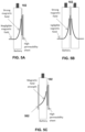
- FIGS. 5 A-C illustrate block diagrams showing magnetic field strength distributions for different example arrangements of the system.
- FIGS. 6 A-B illustrate cross sectional views of typical rechargeable batteries, liquid electrolyte battery (A) and solid electrolyte battery (B).
- FIGS. 7 A-B illustrate magnetic field direction vs charged particle motion direction, coil with no high permeability sheet (A) and coil covered with a high magnetic permeability sheet (B).
- FIGS. 8 A-C illustrate inductive coil equivalent circuit (A), with an additional tuning capacitor (C tune ) connected in series (B) and with an additional tuning capacitor (C tune ) connected in parallel (C), where C battery is an additional parasitic capacitance added by battery.
- FIG. 9 Illustrates current through inductive coil for series and parallel connected tuning capacitor for the system.
- FIGS. 10 A-B illustrate current through coil and input current for series and parallel tuning capacitors.
- FIGS. 11 A-B illustrate sensing circuit arrangements according to various aspects of the system with a first arrangement having a series connected tuning capacitor (A) and a second arrangement having a parallel connected tuning capacitor (B), where the amplifier connected to V IN node is optional.
- a resistor (RSENSE) can be used instead of C Sense in (B).
- FIG. 12 illustrates an exemplary system according to various aspects
- FIGS. 13 A-C illustrate example measurement results using the system according to various aspects where coil resistance (A), coil inductance (B) and battery terminal voltage (C) was measured during battery discharging.
- FIG. 14 illustrates example measurement results conducted to check the effect of battery relaxation using an exemplary system according to various aspects.
- FIGS. 15 A-C illustrates example measured average power, coil resistance, and coil inductance of the inductive coil after compensating the effect of battery current.
- FIG. 16 A-B illustrates an example relation between measured coil resistance and inductance with estimated battery SoC.
- FIGS. 17 A-B illustrates an example block diagram (A) and circuit level implementation example (B) of an inductive coil sensing circuit utilizing a mixer for frequency down conversion with a block diagram.
- FIG. 18 illustrates an example of the system where multiple inductive coils share the same coil drive and sensor interface circuits.
- FIG. 19 illustrates an example of a SoC estimation error of a system utilizing both inductive coil-based and AHC-based SoC estimation where (A) illustrates periodic calibration utilizing inductive coil-based estimation, where (B) illustrates non-periodic calibration utilizing inductive coil-based estimation.
- FIG. 20 illustrates an example block diagram of a battery management system (BMS).
- BMS battery management system
- FIG. 21 illustrates an example of changes in SoC vs VOC curves with battery aging.
- FIG. 22 illustrates an example of an EV charging sequence-constant current and constant voltage (CCCV).
- FIG. 23 illustrates another example of a system with a processor and memory.
- the system and methods described herein provide technical advancements for rechargeable battery diagnostics based in improved measurements of electrochemical state (e.g. state of charge (SoC) and state of health (SoH).
- SoC state of charge
- SoH state of health
- Accurately measuring the electrochemical state of rechargeable batteries is important for prolonging lifetime, maintaining performance, and preventing malfunctions or system failures of many electrical systems that rely on batteries such as electric vehicles (EV) and energy storage systems (ESS).
- Most mission-critical batteries have an in-built battery management system (BMS) that performs cell balancing, thermal management, and SoC/SoH estimation.
- BMS battery management system
- Open Circuit Voltage (OCV) Monitoring Battery output voltage changes depending on its charging and discharging states. It shows the highest voltage when it is fully charged, and the lowest voltage when it is fully discharged.
- the state of charge (SoC) of a battery can be estimated by measuring its open-circuit voltage (OCV) and the pre-measured SoC versus OCV curve.
- a look-up table may provide a mapping between an OCV measurement and a state of charge.
- SoC vs OCV curve depends on temperature, and proper temperature compensation is required for an accurate SoC estimation based on OCV measurements.
- SoC vs OCV curve changes over aging. Unlike temperature, measuring or estimating the state of aging of a battery is not trivial, and the compensation of the aging effect is challenging. The biggest issue is that the battery terminal voltage in open circuit condition changes over time slowly towards its open-circuit voltage because of relaxation.
- the relaxation can take more than 24 hours in the worst case. Because of the relaxation, a battery needs to rest in open circuit conditions typically for more than 3 hours to measure an accurate OCV. Although the OCV-based SoC estimation method has much higher accuracy than most other existing methods, because of the requirement for a long resting time, it is not suitable for online applications.
- AHC Ampere Hour Counting
- a system can track the amount of charge delivered to or drawn from a battery by integrating its current over time.
- the system can estimate the state of charge (SoC) of a battery utilizing the estimated amount of charge. SoC is typically estimated using the equation shown below.
- Ampere hour counting (AHC) based SoC estimation has three issues.
- the constants in the equation such as nominal capacity, coulombic efficiency, and self-discharge rate change over time resulting in increases in SoC estimation error.
- AHC based SoC estimation can provide only the changes in SoC ( ⁇ SoC), not the absolute SoC value.
- ⁇ SoC SoC
- the AHC-based method must be combined with other methods to provide an absolute SoC value.
- One example is combining the AHC method with the OCV method.
- the system can estimate the absolute SoC value using OCV based method after enough resting (off current condition)—for example after parking an electric vehicle overnight. Between the OCV based calibration points, the system can use AHC to estimate SoC, and the estimation error increases over time. If the increased error before the next calibration is within a tolerable range, the system can operate reliably. Consequently, the reliability of the system depends on the frequency of the calibration.
- Impedance-based SoC Estimation The internal impedance of the battery changes during charging and discharging. Hence, a system can estimate the SoC of a battery by measuring its internal impedance. Typically, impedances, both real and imaginary parts, are measured at plural frequencies.
- Impedance-based SoC estimation has four issues.
- impedance is a strong function of temperature and state of aging as well, and separating the effect of SoC from the effect of temperature and aging is challenging.
- battery relaxation affects battery impedance, and compensating the effect of relaxation on impedance is not trivial.
- Fourth, its implementation is not simple. Because plural batteries are connected in series and parallel and the load and charging circuitry also contributes to the impedance, the impedance measurement circuitry has to be carefully designed to isolate the impedance of the target battery from the impedances of other batteries, load, and charging circuits. For the reasons, the method is mostly used in laboratories where the test conditions are tightly controlled and rarely used for online applications.
- ECM Equivalent Circuit Model
- More than one method can be used together to overcome the limitations of the individual method.
- One widely used method is using OCV and AHC together along with a battery equivalent circuit model (ECM).
- the method calculates the amount of charge delivered to or drawn from a battery utilizing the AHC method, estimates the changes in the open-circuit voltage (OCV) based on the amount of charge utilizing the OCV method, and finds the resulting terminal voltage (VT) utilizing the equivalent circuit model.
- OCV open-circuit voltage
- VT terminal voltage
- the system compares the estimated terminal voltage and the measured terminal voltage to correct the estimated SoC value, and the correction process, typically implemented using Extended Kalman Filter (EKF), continues to keep the difference between the estimated and measured terminal voltages minimal.
- EKF Extended Kalman Filter
- the method is becoming popular because of its real-time adaptation capability but has several technical issues.
- the biggest issue is the accuracy of the equivalent circuit model and model parameters.
- the SoC estimation accuracy heavily depends on the accuracy of the circuit model parameters-resistances and capacitance.
- the model parameters are a function of SoC, temperature, and battery aging state, real-time parameter extraction is required.
- the system may include an inductive coil placed on the side of a battery and a current sensor measuring the battery current.
- a thin planar inductive coil is preferred, and the preferred orientation of the planar coil is in parallel with the electrode plates in the battery.
- a sheet of high magnetic permeability material can be placed on top of the inductive coil to reduce interference.
- the size (area) of the inductive coil and the optional sheet is smaller than the area of the battery where the coil is attached.
- each battery can have its own inductive coil and the multiple batteries can share one current sensor.
- the system also can have a temperature sensor to measure temperature and use the measured temperature for temperature compensation.
- one inductive coil is sandwiched between two batteries without a high magnetic permeability sheet, so the coil can measure the electrochemical state of the two batteries simultaneously.
- the inductive coil may be excited using an AC signal with a fixed frequency and generates AC magnetic fields in the battery.
- the frequency and strength of the induced magnetic field are adjusted to make sure that the magnetic field in the battery under measurement is strong enough to induce physical absorption inside of the battery and the strength of the magnetic field on the other side of the battery (outside) is negligible.
- a high excitation frequency over 5 MHz is preferred to increase induced Eddy current and sensitivity.
- the types of physical absorption that can be used for battery state estimation is Eddy current loss because Eddy current changes depending upon the physical and chemical properties of battery electrodes and electrolyte, and the properties of battery electrodes and electrolyte change depending upon the battery electrochemical state.
- Another physical loss, that is unwanted yet unavoidable, is induced by battery current in response to the AC magnetic field.
- electrically charged particles such as electrons or Li ions in Li-based rechargeable batteries move in a magnetic field
- a force perpendicular to the direction of the particle motion and the magnetic field vector is applied to the moving charged particles.
- the force results in a displacement of the charged particles which results in additional loss proportional to the battery current.
- the system may utilize the battery current data measured by a current sensor to eliminate the effect of battery current when estimating the electrochemical state of batteries.
- the system may stores the relation between the battery current and the current induced loss at different temperatures in the form of lookup tables or mathematical formulas and uses the lookup tables or the mathematical formulas to correct the effect of battery current.
- EV electric vehicles
- ESS energy storage systems
- a tuning capacitor may be connected to the inductive coil in series or parallel to form an LC tank to boost and regulate the coil current.
- a sensing element a resistor or a capacitor
- the impedance of the series-connected sensing element at the operating frequency is less than 10% of the LC tank impedance.
- the tuning capacitor is connected in series to the inductive coil to form a series LC tank, the tuning capacitor itself serves as a sensing element.
- the system may calculate the complex impedance, complex power, power factor, coil inductance, and/or coil resistance of the inductive coil by measuring the voltage (both amplitude and phase) across the sensing element.
- the system may improve the measurement accuracy by measuring the input voltage (both amplitude and phase) applied to the LC tank as well. Using the measured input voltage instead of using a pre-known input voltage minimizes the adversary effect of circuit variations.
- the system may optionally use a mixer to bring down the frequency of the electrical signals and hence to use a low-speed analog-to-digital converter (ADC) for signal processing.
- ADC analog-to-digital converter
- the electrochemical state of a battery is determined based on the measured impedance, power, power factor, coil inductance, and/or coil resistance after compensating the effect of battery current.
- the system can also compensate for the effect of temperature using the measured temperature to further improve accuracy.
- the system may apply inductive coil-based battery SoC estimation sporadically or periodically, and apply ampere hour counting (AHC) based SoC estimation between the intervals.
- AHC ampere hour counting
- the error of AHC-based battery SoC estimation increases with time, and the error will be reset when the inductive coil-based battery SoC estimation is activated.
- the system may set or control the interval length to be not too long, so the error of AHC-based battery SoC estimation remains within a target range.
- the system combines the inductive coil-based battery state estimation method with other battery state of health (SoH) estimation methods such as internal resistance measurement and equivalent circuit model (ECM) based estimation to improve SoH estimation accuracy.
- SoH battery state of health
- ECM equivalent circuit model
- battery internal resistance can be relatively easily measured and is a function of battery SoC, SoH, and temperature. If the system can find SoC separately, it can accurately estimate battery SoH using the measured internal resistance and SoC values.
- the system may use the inductive coil-based battery SoC estimation value and the battery internal resistance value to estimate an accurate battery SoH value.
- the inductive coil-based battery SoC estimation method can be combined with open circuit voltage (OCV). The relation between OCV and SoC changes depending upon battery SoH.
- OCV open circuit voltage
- OCV can be measured after long resting such as overnight parking of an electric vehicle.
- the system can perform inductive coil-based SoC measurement, and use the SoC and OCV values to estimate SoH.
- the system can use the SoC value measured at the full-charge condition to estimate SoH.
- CCCV constant current and constant voltage
- Battery SoC at full-charge condition degrades over battery aging, SoH.
- the system may measure SoC using the inductive coil-based method when the battery is at the full-charge condition and use the measured SoC value to estimate SoH.
- FIG. 1 A-B illustrates a first example of a battery diagnostic system 100 (the system).
- the system may be include components which attach to a battery or (or batteries).
- the battery (or batteries) may be included in the system as well.
- the FIG. 1 A illustrates an example of the system and a side view of the battery.
- FIG. 2 B illustrates an example of the system and a front view of the battery. Reference to FIGS. 1 A and 2 B follows the following discussion.
- the system 100 may include an inductive coil 102 and a current sensor 104 .
- the current sensor 104 may include a sensor that generates a signal indicative of current through a conductor attached to a terminal 106 of the battery.
- the battery may be attached to either the anode or cathode terminal.
- the current sensor 104 may include a resistive current sensor connected in series to the current carrying wire, an invasive Hall current sensor connected in series to the current carrying wire, a non-invasive Hall current sensor installed around a wire, and a magneto-resistive current sensor installed around a wire.
- any type of current sensor can be used, and the current sensor can be installed on the anode side or on the cathode side of the battery.
- the coil 104 may include a inductive coil placed on the side of a battery and a current sensor measuring the battery current, as shown in FIG. 1 A-B .
- the inductive coil may include a thin planer coil.
- the preferred orientation of the inductive coil is in parallel with the electrode plates 108 in the battery such that the plane formed by the coil is electrode substance parallel with the planes in the battery.
- the coil when attached to the battery, may have a side that faces the battery and another side that faces away from the battery.
- a sheet of high magnetic permeability material can be placed on top of the inductive coil 102 to reduce interference.
- the sheet of magnetically permeable material may be applied to the inductive coil 102 on side the inductive coil 102 that faces away from the battery B.
- the area of the thin coil will be smaller than the area of the side of the battery in which the coil is attached.
- FIG. 2 illustrates an example of the system with multiple batteries.
- EV electrical vehicles
- ESS energy storage systems
- multiple batteries are connected in series and/or parallel.
- each battery may share a current sensor as shown in FIG. 2 .
- Each of the batteries may have a separate coil.
- FIG. 3 illustrates an example of the system in which a battery has multiple inductive coils.
- the multiple inductive coils on a battery may be used for determining the spatial distribution of electrochemical states of a battery.
- the system can also have a temperature sensor 303 or multiple temperature sensors and use the measured temperature for temperature compensation.
- FIG. 4 A-B illustrates an example of the system inductive coils positioned between multiple batteries.
- an inductive coil can be sandwiched between two batteries without a high magnetic permeability sheet, as shown in FIG. 4 A , and the inductive coil can be used to estimate the average electrochemical state of the batteries sandwiching it.
- high magnetic permeability sheets are used, as shown in FIG. 4 B , the system can measure the electrochemical state of individual batteries independently.
- FIG. 5 A-C illustrate a strength curve of the magnetic field for various inductive coil configurations.
- the inductive coil may be excited using an AC signal with a fixed frequency and may generate AC magnetic fields in the battery.
- the generated magnetic field strength decays rapidly with increasing distance from the coil, and the system adjusts the coil current to generate a strong magnetic field inside of the battery but a negligibly weak magnetic field in the outside area of the battery.
- FIG. 5 A when a high magnetic permeability sheet covers the coil, magnetic fields will be formed only on one side of the coil. Without the sheet, magnetic fields will be formed on both sides of the coil.
- a battery may be placed on either side of the coil, respectively (see also FIG. 4 A ).
- an additional high magnetic permeability sheet 502 can be placed on the opposite side of the battery, as shown in FIG. 5 C , to block the magnetic fields leaking to the outside of the battery.
- FIG. 6 A-B shows a simplified cross-sectional view of Li ion batteries—prismatic and pouch cells.
- the example uses Li ion batteries, but any kind of Li or non-Li based rechargeable batteries are suitable.
- FIG. 6 A -Bs shows only one layer of anode-cathode combination for simplicity. Most batteries have multiple layers, and the magnetic fields penetrate over multiple layers.
- the Eddy current losses in the battery case, if the case material is conductive, in the anode-side current collector metal, and in the cathode side current collector metal are fixed because they do not or minimally change with battery electrochemical states.
- the Eddy current losses in the anode, electrolyte, separator, and cathode depend upon the battery electrochemical state. For example, with charging and discharging, the Li contents in the anode and cathode change, and their resistances and densities change as well. Consequently, Eddy current losses in anode and cathode change depending upon battery charging and discharging states.
- anode, electrolyte, and cathode materials have very different electrical resistivities and densities, and the one that has the lowest resistivity and density shows the biggest level of Eddy current loss.
- the system can determine the battery electrochemical state by measuring the level of Eddy currents.
- an electrically charged particle such as an electron or Li ion moves in a magnetic field
- a force perpendicular to the direction of the motion of the particle and the magnetic field vector is applied to the particle.
- the magnetic field is AC and the battery current changes much slower than the AC coil excitation frequency
- the force changes its direction periodically at the excitation frequency.
- the force results in the displacement of the particle which results in an extra loss.
- battery current is essentially a group motion of electrons and Li ions in the case of Li ion batteries, the extra loss is proportional to battery current.
- FIG. 7 A-B conceptually shows the magnetic fields induced by an inductive coil and the motion of electrons and Li ions in a battery.
- anode, electrolyte, and cathode electrons and Li ions drift mostly in the x-direction, and the magnetic fields have a certain level of y-direction and z-direction components except for the center point of the coil.
- the y- and z-direction components are small in the center area of the coil, and big under the coil wire area.
- electrons mostly drift in the y-direction, and the magnetic fields have a strong x-direction component.
- the system may utilize the battery current data measured by a current sensor to exclude the effect of battery current when estimating the electrochemical state of a battery.
- the system may store the relation between battery current and current-induced loss at different temperatures in the form of lookup tables or mathematical formulas and uses the lookup tables or mathematical formulas to exclude the effect of battery current.
- EV electric vehicles
- ESS energy storage systems
- FIG. 8 A-C illustrates an example of the system with a tuning capacitor to provide efficient signal measurement.
- the tuning capacitor (C tune ) may be connected to the inductive coil in series ( FIG. 8 A ) or parallel ( FIG. 8 B ) to form an LC tank, and to boost or regulate the coil current.
- V IN input voltage
- FIG. 8 B the tuning capacitor
- the coil current is higher than the LC tank input current (I IN ) if the excitation frequency is close to the LC tank resonance frequency and the LC tank quality factor is bigger than one.
- FIG. 9 shows inductor coil currents for series-connected LC tank and parallel-connected LC tank under the same input voltage (V IN ) and resonance frequency conditions.
- Series LC tank shows much higher inductor coil current near the resonance frequencies than that of parallel LC tank because of its voltage boosting. Higher coil current generates a stronger magnetic field and could provide higher signal-to-noise ratios and sensitivities for the measurements.
- the series LC tank connection its input current is almost the same with the inductor coil current, as shown in FIG. 10 A .
- the inductor coil current is much higher than the input current (I IN ), as shown in FIG.
- the system may measure the input current (I IN ), both amplitude and phase.
- an additional element for parallel connection, an additional element, a resistor or a capacitor, can be used to sense the current as shown in FIG. 11 B .
- a capacitor is preferred because it blocks DC signal.
- the series-connected tuning capacitor (C tune ) itself can be used as a current sensing element, as shown in FIG. 11 A , eliminating the need for a separate sensing element.
- the system can use the known input voltage V IN to calculate complex impedance and complex power or can use additional circuitry to measure V IN . Using measured V IN would help to minimize the uncertainty introduced by the output impedance of the driving amplifier, which may suffer from temperature and process variations.
- V IN and V SENSE are measured, the system can calculate complex impedance and complex power. If required, the system can also calculate the inductive coil inductance L Coil and resistance R Coil .
- I IN V S ⁇ e ⁇ n ⁇ s ⁇ e Z S ⁇ e ⁇ n ⁇ s ⁇ e
- I IN V S ⁇ e ⁇ n ⁇ s ⁇ e Z S ⁇ e ⁇ n ⁇ s ⁇ e
- the system determines the battery electrochemical state using the calculated complex impedance Z LC , inductance L coil , resistance R Coil , complex power S LC and/or power factor PF LC .
- FIG. 12 illustrates an example of the system.
- the system may include a coil driver and sensor interface.
- the coil driver may send current to one or more coils to batteries monitored by the system.
- the sensor interface may measure V in and V Sense . In some examples, the sensor interface may down-converts these signals to a lower frequency.
- the system may further include a battery current control unit.
- the battery current control unit may measure the current across the current sensor. Alternatively or in addition, the battery current control unit may control the battery current applied to a battery under test.
- the system may include a controller.
- the controller may receive V in and V sense .
- the controller may convert the signals into digital using ADC and collects battery current data from the battery current control unit.
- the controller may calculate the amplitude and phase of the voltage signals first and calculates complex power, power factor, complex impedance, coil inductance, and coil resistance using the voltage signals and correct them using the current data.
- the microprocessor or a separate computing unit determines battery electrochemical states such as SoC and SoH utilizing the measured complex power, power factor, complex impedance, coil inductance, and/or coil resistance.
- FIG. 13 A-C shows the measured inductive coil resistance, inductance, and terminal voltage during battery discharging for a 10 Ah Li-polymer battery.
- the calculated resistance and inductance change because of the extra loss caused by moving electrically charged particles. It clearly shows that the effect of moving charged particles (battery current) is significant, proportional to the battery current, and must be excluded for an accurate battery electrochemical state estimation.
- FIG. 13 A-C also shows that the system does not suffer from battery polarization and relaxation. When battery current is zero, the battery terminal voltage keeps changing toward its open circuit voltage (OCV) because of battery polarization and relaxation. The relaxation typically takes several hours which makes terminal voltage-based battery electrochemical state estimation practically impossible.
- OCV open circuit voltage
- FIG. 14 A-C shows the changes in the measured inductance over two hours after cutting off the battery current, and it clearly shows that the inductance does not change over the two hours period.
- the measured impedance, power, power factor, coil inductance, and coil resistance do not show any effect of battery polarization and relaxation. It means that the system can perform the battery electrochemical state estimation including the compensation for the loss induced by battery current at any time almost instantly without worrying about battery polarization and relaxation. No existing system can do such an instant battery state estimation.
- FIG. 15 A-C illustrates the measured and calculated average power (real part of the complex power), resistance, and inductance after compensating the effect of battery currents.
- the measurement results show a clear correlation between the battery state of charge (SoC) and the measured data after excluding the effect of battery current. Five repeated measurements provided consistent results.
- SoC battery state of charge
- FIG. 16 A-B illustrates the relation between the estimated battery SoC and the measured inductive coil inductance and resistance.
- the implemented exemplary system conducts the measurement 8 times per second.
- the plots in FIG. 15 A-C used the raw measurement data, and the SoC estimation shown FIG. 16 -A-B used the moving average to filter out the measurement noise.
- the system can optionally use a mixer to down-convert the signal frequency to a lower frequency.
- a mixer to down-convert the signal frequency to a lower frequency.
- Eddy current loss increases with increasing frequency
- using a high-frequency excitation signal preferably higher than 5 MHz, is beneficial for inductive coil-based battery electrochemical state measurement.
- the example embodiment used 18.7 MHz.
- the system may include a high-speed analog-to-digital converter (ADC).
- ADC analog-to-digital converter
- ADC analog-to-digital converter
- the issue can be mitigated by down-converting the frequency to a lower frequency using a mixer.
- FIG. 17 A-B illustrates an example of a dual-output phase-locked loop (PLL) which generates 18.7 MHz and 18.732 MHz (LO) signals.
- the 18.7 MHz signal is used to excite the inductive coil, and the 18.732 MHz signal is used for a mixer that down-converts the 18.7 MHz signal to 32 kHz.
- An active or passive bandpass filter centered at 32 kHz passes only the 32 kHz down-converted signal, and the following ADC samples the 32 kHz signal.
- a digital processor calculates the amplitude and phase of the 32 kHz signal first and uses the amplitude and phase to calculate the amplitude and phase of the original 18.7 MHz signal.
- FIG. 18 illustrates a second example of the system with a battery management system 1802 .
- One or more may be coils connected to the battery management system.
- the battery management system may include the coil driver and sensor interface, controller, and/or the battery discharge unit, which are described in reference to FIG. 12 .
- the battery management system may cause excitation of one or more coils, sequentially or simultaneously.
- the battery diagnostic circuitry may receive battery current from one or more current sensors. The current sensor(s) are not shown in FIG. 18 for simplicity.
- the system may use a combination of the inductive coil-based battery electrochemical state estimation and ampere hour counting (AHC) based battery electrochemical state estimation.
- the inductive coil-based sensing method can estimate battery electrochemical states such as SoC almost instantly and its estimation error does not accumulate over time.
- One potential issue of the inductive coil-based method is its relatively high-power consumption. To generate a strong enough magnetic field, enough amount of current must be pumped into the coil. The stronger the magnetic field the stronger the signal-to-noise ratio. Because of the need for a high coil current, the sensing module consumes much more power than typical voltage, current, and temperature sensors that are commonly used for battery management.
- the high-power consumption issue can be serious for systems that use a large number of batteries such as electric vehicles (EV) and energy storage systems (ESS).
- EV electric vehicles
- ESS energy storage systems
- the system addresses the issue by using both inductive coil-based and AHC-based methods in a complementary manner.
- the system conducts the inductive coil-based SoC estimation sporadically or periodically and uses AHC-based SoC estimation between the intervals.
- AHC-based battery SoC measurement method provides a fairly accurate estimation of the changes in SoC (DSoC) over a short period of time.
- DoC SoC
- it does not provide absolute SoC value, and its estimation error increases over time because of its integrating nature.
- the AHC-based SoC estimation result must be calibrated often before the accumulated error becomes too big.
- FIG. 19 A-B illustrates using OCV-based SoC estimation for calibrations.
- OCV-based SoC estimation requires a long resting, typically more than 3 hours, at zero current condition, performing the calibration often is challenging for many practical applications. For example, for EVs, the calibration can be performed during overnight parking, but the SoC estimation error can grow to an unacceptable level during long driving. For ESS, a zero-current condition for more than 3 hours required for OCV-based SoC estimation rarely happens.
- the system may apply inductive coil-based SoC estimation periodically or sporadically for the calibration.
- performing the inductive coil-based SoC estimation and calibration once per hour will mitigate the power consumption issue of the inductive coil-based method, and keep the SoC estimation error of the AHC-based method well within the acceptable range, as depicted in FIG. 19 A .
- the system can also perform the inductive coil-based SoC estimation and calibration irregularly based on pre-defined calibration criterion, as shown in FIG. 19 B .
- the system can perform the inductive coil-based SoC estimation and calibration when the accumulated battery current since the last calibration reaches a pre-defined value.
- the system can perform the inductive coil-based SoC estimation and calibration when the battery current sensor reports a small current, smaller than a pre-defined value, so it can eliminate the need for compensating the effect of battery current.
- the system can define the criterion based on elapsed time, integrated battery current value, instantaneous battery current value, temperature, battery terminal voltage, and target accuracy.
- the system can momentarily turn off the battery current, both charging and discharging currents, while performing the measurement. This will reduce the amount of computation required for SoC estimation by eliminating or minimizing the computation for battery current compensation.
- FIG. 20 illustrates an example of charging and discharging paths.
- the system may include a charging switch and a discharging switch.
- Battery current can be turned off by turning off the charging and discharging path switches. Even when the switches are off, the battery management system (BMS) may draw a small amount of current from the battery. But, because the current is small and changes in a very small range, compensating its effect is much easier or not required.
- BMS battery management system
- the whole sensing and computation within 125 msec so the required current cut off time can be very short.
- the system may combine the inductive coil-based battery state estimation method with other battery state estimation methods such as internal resistance measurement and open circuit voltage measurement to improve SoH estimation accuracy.
- battery internal resistance can be relatively easily measured and is a function of battery SoC, SoH, and temperature. Compensating the effect of temperature is relatively easy but separating the contributions from SoC and SoH is not trivial. Because it depends on both battery SoC and SoH, the system needs to know SoC to accurately estimate SoH.
- the system can use the SoC measured using the inductive coil-based method and use it to estimate SoH.
- Another example is combining inductive-coil-based measurement and OCV measurement. Unlike SoC, SoH measurement does not need to be continuous or frequent.
- Battery OCV can be measured after long, typically more than 3 hours, resting such as overnight parking of electric vehicles.
- the relation between OCV and SoC changes over battery aging, as depicted in FIG. 21 , and the system can estimate the degree of battery aging, SoH, using measured OCV if SoC is known.
- the system can use inductive coil-based SoC measurement data and OCV measurement data to estimate SoH.
- Another way of estimating SoH, for the batteries in EVs is by using the inductive coil-based SoC measurement value at the full-charge condition.
- EV battery charging typically uses CCCV (constant current and constant voltage) method as depicted in FIG. 22 .
- EV battery charging initially uses a constant current, and, once the battery terminal voltage reaches a preset value, the charging changes to a constant voltage mode. Battery charging is completed when the charging current drops down to a present value, and the battery reaches the full-charge condition. With battery aging, battery SoC at a full-charge condition degrades. The system can estimate battery SoH by measuring SoC at the full-charge condition.
- the system may be implemented with additional, different, or fewer components than illustrated. Each component may include additional, different, or fewer components.
- FIG. 23 illustrates another example of the system 100 .
- the system 100 may include communication interfaces 812 , input interfaces 828 and/or system circuitry 814 .
- the system circuitry 814 may include a processor 816 or multiple processors. Alternatively or in addition, the system circuitry 814 may include memory 820 .
- the processor 816 may be in communication with the memory 820 . In some examples, the processor 816 may also be in communication with additional elements, such as the communication interfaces 812 , the input interfaces 828 , and/or the user interface 818 . Examples of the processor 816 may include a general processor, a central processing unit, logical CPUs/arrays, a microcontroller, a server, an application specific integrated circuit (ASIC), a digital signal processor, a field programmable gate array (FPGA), and/or a digital circuit, analog circuit, or some combination thereof.
- ASIC application specific integrated circuit
- FPGA field programmable gate array
- the processor 816 may be one or more devices operable to execute logic.
- the logic may include computer executable instructions or computer code stored in the memory 820 or in other memory that when executed by the processor 816 , cause the processor 816 to perform the operations the system and methods described herein.
- the computer code may include instructions executable with the processor 816 .
- the memory 820 may be any device for storing and retrieving data or any combination thereof.
- the memory 820 may include non-volatile and/or volatile memory, such as a random access memory (RAM), a read-only memory (ROM), an erasable programmable read-only memory (EPROM), or flash memory.
- the memory 820 may include an optical, magnetic (hard-drive), solid-state drive or any other form of data storage device.
- the memory 820 may include the system 100 and/or any other component or sub-component of the system 100 described herein.
- the user interface 818 may include any interface for displaying graphical information.
- the system circuitry 814 and/or the communications interface(s) 812 may communicate signals or commands to the user interface 818 that cause the user interface to display graphical information.
- the user interface 818 may be remote to the system 100 and the system circuitry 814 and/or communication interface(s) may communicate instructions, such as HTML, to the user interface to cause the user interface to display, compile, and/or render information content.
- the content displayed by the user interface 818 may be interactive or responsive to user input.
- the user interface 818 may communicate signals, messages, and/or information back to the communications interface 812 or system circuitry 814 .
- the system 100 may be implemented in many ways.
- the system 100 may be implemented with one or more logical components.
- the logical components of the system 100 may be hardware or a combination of hardware and software.
- the logical components may include the system or any component or subcomponent of the system 100 .
- each logic component may include an application specific integrated circuit (ASIC), a Field Programmable Gate Array (FPGA), a digital logic circuit, an analog circuit, a combination of discrete circuits, gates, or any other type of hardware or combination thereof.
- each component may include memory hardware, such as a portion of the memory 820 , for example, that comprises instructions executable with the processor 816 or other processor to implement one or more of the features of the logical components.
- any one of the logical components includes the portion of the memory that comprises instructions executable with the processor 816
- the component may or may not include the processor 816 .
- each logical component may just be the portion of the memory 820 or other physical memory that comprises instructions executable with the processor 816 , or other processor(s), to implement the features of the corresponding component without the component including any other hardware. Because each component includes at least some hardware even when the included hardware comprises software, each component may be interchangeably referred to as a hardware component.
- a computer readable storage medium for example, as logic implemented as computer executable instructions or as data structures in memory. All or part of the system and its logic and data structures may be stored on, distributed across, or read from one or more types of computer readable storage media. Examples of the computer readable storage medium may include a hard disk, a floppy disk, a CD-ROM, a flash drive, a cache, volatile memory, non-volatile memory, RAM, flash memory, or any other type of computer readable storage medium or storage media.
- the computer readable storage medium may include any type of non-transitory computer readable medium, such as a CD-ROM, a volatile memory, a non-volatile memory, ROM, RAM, or any other suitable storage device.
- the processing capability of the system may be distributed among multiple entities, such as among multiple processors and memories, optionally including multiple distributed processing systems.
- Parameters, databases, and other data structures may be separately stored and managed, may be incorporated into a single memory or database, may be logically and physically organized in many different ways, and may implemented with different types of data structures such as linked lists, hash tables, or implicit storage mechanisms.
- Logic such as programs or circuitry, may be combined or split among multiple programs, distributed across several memories and processors, and may be implemented in a library, such as a shared library (for example, a dynamic link library (DLL).
- DLL dynamic link library
- the respective logic, software or instructions for implementing the processes, methods and/or techniques discussed above may be provided on computer readable storage media.
- the functions, acts or tasks illustrated in the figures or described herein may be executed in response to one or more sets of logic or instructions stored in or on computer readable media.
- the functions, acts or tasks are independent of the particular type of instructions set, storage media, processor or processing strategy and may be performed by software, hardware, integrated circuits, firmware, micro code and the like, operating alone or in combination.
- processing strategies may include multiprocessing, multitasking, parallel processing and the like.
- the instructions are stored on a removable media device for reading by local or remote systems.
- the logic or instructions are stored in a remote location for transfer through a computer network or over telephone lines.
- the logic or instructions are stored within a given computer and/or central processing unit (“CPU”).
- a processor may be implemented as a microprocessor, microcontroller, application specific integrated circuit (ASIC), discrete logic, or a combination of other type of circuits or logic.
- memories may be DRAM, SRAM, Flash or any other type of memory.
- Flags, data, databases, tables, entities, and other data structures may be separately stored and managed, may be incorporated into a single memory or database, may be distributed, or may be logically and physically organized in many different ways.
- the components may operate independently or be part of a same apparatus executing a same program or different programs.
- the components may be resident on separate hardware, such as separate removable circuit boards, or share common hardware, such as a same memory and processor for implementing instructions from the memory.
- Programs may be parts of a single program, separate programs, or distributed across several memories and processors.
- a second action may be said to be “in response to” a first action independent of whether the second action results directly or indirectly from the first action.
- the second action may occur at a substantially later time than the first action and still be in response to the first action.
- the second action may be said to be in response to the first action even if intervening actions take place between the first action and the second action, and even if one or more of the intervening actions directly cause the second action to be performed.
- a second action may be in response to a first action if the first action sets a flag and a third action later initiates the second action whenever the flag is set.
- the phrases “at least one of ⁇ A>, ⁇ B>, . . . and ⁇ N>” or “at least one of ⁇ A>, ⁇ B>, . . . ⁇ N>, or combinations thereof” or “ ⁇ A>, ⁇ B>, . . . and/or ⁇ N>” are defined by the Applicant in the broadest sense, superseding any other implied definitions hereinbefore or hereinafter unless expressly asserted by the Applicant to the contrary, to mean one or more elements selected from the group comprising A, B, . . . and N.
- the phrases mean any combination of one or more of the elements A, B, . . . or N including any one element alone or the one element in combination with one or more of the other elements which may also include, in combination, additional elements not listed.
Landscapes
- Engineering & Computer Science (AREA)
- General Chemical & Material Sciences (AREA)
- Chemical & Material Sciences (AREA)
- Chemical Kinetics & Catalysis (AREA)
- Electrochemistry (AREA)
- Power Engineering (AREA)
- Manufacturing & Machinery (AREA)
- Computer Networks & Wireless Communication (AREA)
- Physics & Mathematics (AREA)
- General Physics & Mathematics (AREA)
- Health & Medical Sciences (AREA)
- General Health & Medical Sciences (AREA)
- Medical Informatics (AREA)
- Secondary Cells (AREA)
Abstract
Description
-
- where;
- SoC(0)=initial SoC
- CN=nominal capacity
- η=coulombic efficiency
- Sd=self-discharge rate
- where;
-
- where,
- IIN=input phasor current
- VSense=phasor voltage across CSense (or Rsense if resistor is used for current sensing)
- ZSense=impedance of current sensing element at the excitation frequency
where,
-
- VIN=Input phasor voltage
- ZLC=LC tank impedance
- YLC=LC tank admittance
where,
-
- SLC=complex power of the parallel LC tank
- IIN*=complex conjugate of input phasor current
where,
-
- PFLC=power factor of the parallel LC tank
Y Coil =Y LC −jω(C int +C battery +C tune)
where,
-
- YCoil=admittance of the branch that has inductor and resistor
- Cint=intrinsic parasitic capacitance of the inductive coil
- Cbattery=additional capacitance added by battery
- Ctune=tuning capacitor added to form parallel LC tank
where,
-
- LCoil=coil inductance
- f=excitation frequency
where,
-
- RCoil=coil parasitic resistance
where,
-
- IIN=input phasor current
- VSense=phasor voltage across CTune
- ZSense=impedance of current sensing element CTune at the excitation frequency
where,
-
- VIN=Input phasor voltage
- ZLC=LC tank impedance without CTune
- YLC=LC tank admittance without CTune
where,
-
- SLC=complex power of the inductive coil including parasitic capacitance
- IIN*=complex conjugate of input phasor current
where,
-
- PFLC=power factor of the inductive coil including parasitic capacitance
Y Coil =Y LC −jω(C int +C battery)
where,
-
- YCoil=admittance of the branch that has inductor and resistor
- Cint=intrinsic parasitic capacitance of the inductive coil
- Cbattery=additional capacitance added by battery
where,
-
- LCoil=coil inductance
- f=excitation frequency
where,
-
- RCoil=coil parasitic resistance
Claims (23)
Priority Applications (1)
| Application Number | Priority Date | Filing Date | Title |
|---|---|---|---|
| US17/382,279 US12184106B2 (en) | 2020-07-21 | 2021-07-21 | System and methods for rechargeable battery diagnostics |
Applications Claiming Priority (2)
| Application Number | Priority Date | Filing Date | Title |
|---|---|---|---|
| US202063054567P | 2020-07-21 | 2020-07-21 | |
| US17/382,279 US12184106B2 (en) | 2020-07-21 | 2021-07-21 | System and methods for rechargeable battery diagnostics |
Publications (2)
| Publication Number | Publication Date |
|---|---|
| US20220190614A1 US20220190614A1 (en) | 2022-06-16 |
| US12184106B2 true US12184106B2 (en) | 2024-12-31 |
Family
ID=81941890
Family Applications (1)
| Application Number | Title | Priority Date | Filing Date |
|---|---|---|---|
| US17/382,279 Active 2043-04-19 US12184106B2 (en) | 2020-07-21 | 2021-07-21 | System and methods for rechargeable battery diagnostics |
Country Status (1)
| Country | Link |
|---|---|
| US (1) | US12184106B2 (en) |
Families Citing this family (9)
| Publication number | Priority date | Publication date | Assignee | Title |
|---|---|---|---|---|
| CN111293739B (en) * | 2018-12-10 | 2022-05-17 | 华为技术有限公司 | A charging method and device |
| CN118922730A (en) * | 2021-12-29 | 2024-11-08 | 福特全球技术公司 | Techniques for detecting battery cell degradation and impending battery pack failure using a battery charger and battery management system |
| CN115267582B (en) * | 2022-08-29 | 2025-05-02 | 江苏海基新能源股份有限公司 | A method for determining the capacity loss type of lithium-ion batteries during high-temperature storage |
| EP4619773A1 (en) * | 2022-11-18 | 2025-09-24 | Qorvo US, Inc. | Battery current measurement in an electrical circuit |
| DE102023200582B3 (en) * | 2023-01-25 | 2024-06-27 | Robert Bosch Gesellschaft mit beschränkter Haftung | Method and device for diagnosing a current sensor in an electrically operated technical device with a device battery |
| CN116338299B (en) * | 2023-05-29 | 2023-08-04 | 广东电网有限责任公司佛山供电局 | Method and system for testing output power factor of charging module of direct current system |
| CN117030162B (en) * | 2023-10-09 | 2024-02-20 | 宁德时代新能源科技股份有限公司 | Liquid leakage detection circuit, system, method, device, equipment and battery management system |
| CN117578679B (en) * | 2024-01-15 | 2024-03-22 | 太原理工大学 | Lithium battery intelligent charging control method based on reinforcement learning |
| CN119470182A (en) * | 2025-01-14 | 2025-02-18 | 宁德时代新能源科技股份有限公司 | Battery slurry detection device and method |
Citations (8)
| Publication number | Priority date | Publication date | Assignee | Title |
|---|---|---|---|---|
| US5093624A (en) * | 1989-03-13 | 1992-03-03 | Yuasa Battery (Uk) Limited | Battery monitoring |
| US5132626A (en) * | 1989-05-31 | 1992-07-21 | Amoco Corporation | Electrolytic storage cell monitoring system |
| US5250903A (en) | 1989-05-31 | 1993-10-05 | Amoco Corporation | Method and apparatus using oscillatory magnetic field to determine state of charge of an electrolytic storage cell |
| US5537042A (en) * | 1994-11-18 | 1996-07-16 | Eldec Corporation | Method and system for unobtrusively measuring physical properties in electrochemical processes |
| US20090013521A1 (en) * | 2007-07-10 | 2009-01-15 | Panasonic Ev Energy Co., Ltd | Reconstituted battery pack, reconstituted battery pack producing method, reconstituted battery pack using method, and reconstituted battery pack control system |
| US20130154652A1 (en) * | 2009-02-05 | 2013-06-20 | Maria F. Rice | Battery state of charge sensor |
| US9851408B2 (en) | 2008-06-05 | 2017-12-26 | Cadex Electronics Inc. | Methods and apparatus for battery testing |
| US20210396817A1 (en) * | 2018-09-25 | 2021-12-23 | Bayerische Motoren Werke Aktiengesellschaft | Detection of Abnormal Self-Discharge of Lithium Ion Cells, and Battery System |
-
2021
- 2021-07-21 US US17/382,279 patent/US12184106B2/en active Active
Patent Citations (8)
| Publication number | Priority date | Publication date | Assignee | Title |
|---|---|---|---|---|
| US5093624A (en) * | 1989-03-13 | 1992-03-03 | Yuasa Battery (Uk) Limited | Battery monitoring |
| US5132626A (en) * | 1989-05-31 | 1992-07-21 | Amoco Corporation | Electrolytic storage cell monitoring system |
| US5250903A (en) | 1989-05-31 | 1993-10-05 | Amoco Corporation | Method and apparatus using oscillatory magnetic field to determine state of charge of an electrolytic storage cell |
| US5537042A (en) * | 1994-11-18 | 1996-07-16 | Eldec Corporation | Method and system for unobtrusively measuring physical properties in electrochemical processes |
| US20090013521A1 (en) * | 2007-07-10 | 2009-01-15 | Panasonic Ev Energy Co., Ltd | Reconstituted battery pack, reconstituted battery pack producing method, reconstituted battery pack using method, and reconstituted battery pack control system |
| US9851408B2 (en) | 2008-06-05 | 2017-12-26 | Cadex Electronics Inc. | Methods and apparatus for battery testing |
| US20130154652A1 (en) * | 2009-02-05 | 2013-06-20 | Maria F. Rice | Battery state of charge sensor |
| US20210396817A1 (en) * | 2018-09-25 | 2021-12-23 | Bayerische Motoren Werke Aktiengesellschaft | Detection of Abnormal Self-Discharge of Lithium Ion Cells, and Battery System |
Non-Patent Citations (4)
| Title |
|---|
| Battery Management System Tutorial, www.renesas.com/US/en/products/power-power-management/battery-management-system-tutorial, pp. 1-9, 2018. |
| Hauser, A. et al., High-voltage battery management systems (BMS) for electric vehicles, Advances in Battery Technologies for Electric Vehicles, Woodhead Publishing, 11, pp. 265-282, 2015. |
| Li, Y. et al., A combination Kalman filter approach for State of Charge estimation of lithium-ion battery considering model uncertainty, Energy, 109, pp. 933-946, 2016. |
| Ouyang, M. et al., Determination of the battery pack capacity considering the estimation error using a Capacity-Quantity diagram, Applied Energy, 177, pp. 384-392, 2016. |
Also Published As
| Publication number | Publication date |
|---|---|
| US20220190614A1 (en) | 2022-06-16 |
Similar Documents
| Publication | Publication Date | Title |
|---|---|---|
| US12184106B2 (en) | System and methods for rechargeable battery diagnostics | |
| US8855956B2 (en) | Method and system for determining state of charge of an energy delivery device | |
| JP4638195B2 (en) | Battery degradation degree estimation device | |
| US10916813B2 (en) | Battery management apparatus and method for calibrating a state of charge of a battery | |
| CN108291944B (en) | battery management device | |
| US9176194B2 (en) | Temperature compensation for magnetic determination method for the state of charge of a battery | |
| EP1555537B1 (en) | Battery remaining capacity measuring apparatus | |
| CN113785209B (en) | Method for detecting abnormal battery cells | |
| JP6019368B2 (en) | Power storage device state estimation method | |
| US7541814B2 (en) | Method and device for determining the charge of a battery | |
| EP2089731B1 (en) | Apparatus and method for determination of the state-of-charge of a battery when the battery is not in equilibrium | |
| US20020193954A1 (en) | Method of detecting residual capacity of secondary battery | |
| Eichi et al. | Modeling and analysis of battery hysteresis effects | |
| US20230358810A1 (en) | Method for estimating state of charge of battery | |
| US20140149058A1 (en) | Measuring devices of remaining battery life and measuring methods thereof | |
| KR20040060921A (en) | Method for estimating polarization voltage of secondary cell, method and device for estimating remaining capacity of secondary cell, battery pack system, and electric vehicle | |
| CN109964137A (en) | Apparatus and method for estimating capacity retention rate of secondary battery | |
| WO2013025738A2 (en) | Apparatus and method for accurate energy device state-of-health (soh) monitoring | |
| Howey et al. | Impedance measurement for advanced battery management systems | |
| CN113242977A (en) | Estimating SOH and SOC of electrochemical element | |
| CN100460879C (en) | Judgment method of capacitor deterioration | |
| US20220291286A1 (en) | Correction method for estimated state-of-charge value of energy storage device, management apparatus for energy storage device, and energy storage apparatus | |
| JP2008107168A (en) | Battery characteristic detection method and battery characteristic detection apparatus | |
| Tang et al. | Capacity estimation for Li-ion batteries | |
| JP2003068369A (en) | Method and apparatus for detecting total capacity of secondary battery |
Legal Events
| Date | Code | Title | Description |
|---|---|---|---|
| FEPP | Fee payment procedure |
Free format text: ENTITY STATUS SET TO UNDISCOUNTED (ORIGINAL EVENT CODE: BIG.); ENTITY STATUS OF PATENT OWNER: SMALL ENTITY |
|
| FEPP | Fee payment procedure |
Free format text: ENTITY STATUS SET TO SMALL (ORIGINAL EVENT CODE: SMAL); ENTITY STATUS OF PATENT OWNER: SMALL ENTITY |
|
| AS | Assignment |
Owner name: PURDUE RESEARCH FOUNDATION, INDIANA Free format text: ASSIGNMENT OF ASSIGNORS INTEREST;ASSIGNORS:JUNG, BYUNGHOO;PARK, CHIWOOK;REEL/FRAME:057657/0064 Effective date: 20210818 |
|
| STPP | Information on status: patent application and granting procedure in general |
Free format text: DOCKETED NEW CASE - READY FOR EXAMINATION |
|
| STPP | Information on status: patent application and granting procedure in general |
Free format text: NON FINAL ACTION MAILED |
|
| STPP | Information on status: patent application and granting procedure in general |
Free format text: NOTICE OF ALLOWANCE MAILED -- APPLICATION RECEIVED IN OFFICE OF PUBLICATIONS |
|
| STPP | Information on status: patent application and granting procedure in general |
Free format text: PUBLICATIONS -- ISSUE FEE PAYMENT VERIFIED |
|
| STCF | Information on status: patent grant |
Free format text: PATENTED CASE |