US12183622B2 - Semiconductor structure comprising an air chamber and method of manufacturing the same - Google Patents
Semiconductor structure comprising an air chamber and method of manufacturing the same Download PDFInfo
- Publication number
- US12183622B2 US12183622B2 US17/652,338 US202217652338A US12183622B2 US 12183622 B2 US12183622 B2 US 12183622B2 US 202217652338 A US202217652338 A US 202217652338A US 12183622 B2 US12183622 B2 US 12183622B2
- Authority
- US
- United States
- Prior art keywords
- trench
- isolation structure
- word line
- sacrificial
- conductive layer
- Prior art date
- Legal status (The legal status is an assumption and is not a legal conclusion. Google has not performed a legal analysis and makes no representation as to the accuracy of the status listed.)
- Active, expires
Links
Images


Classifications
-
- H—ELECTRICITY
- H01—ELECTRIC ELEMENTS
- H01L—SEMICONDUCTOR DEVICES NOT COVERED BY CLASS H10
- H01L21/00—Processes or apparatus adapted for the manufacture or treatment of semiconductor or solid state devices or of parts thereof
- H01L21/70—Manufacture or treatment of devices consisting of a plurality of solid state components formed in or on a common substrate or of parts thereof; Manufacture of integrated circuit devices or of parts thereof
- H01L21/71—Manufacture of specific parts of devices defined in group H01L21/70
- H01L21/76—Making of isolation regions between components
- H01L21/762—Dielectric regions, e.g. EPIC dielectric isolation, LOCOS; Trench refilling techniques, SOI technology, use of channel stoppers
- H01L21/76224—Dielectric regions, e.g. EPIC dielectric isolation, LOCOS; Trench refilling techniques, SOI technology, use of channel stoppers using trench refilling with dielectric materials
-
- H—ELECTRICITY
- H01—ELECTRIC ELEMENTS
- H01L—SEMICONDUCTOR DEVICES NOT COVERED BY CLASS H10
- H01L21/00—Processes or apparatus adapted for the manufacture or treatment of semiconductor or solid state devices or of parts thereof
- H01L21/70—Manufacture or treatment of devices consisting of a plurality of solid state components formed in or on a common substrate or of parts thereof; Manufacture of integrated circuit devices or of parts thereof
- H01L21/71—Manufacture of specific parts of devices defined in group H01L21/70
- H01L21/76—Making of isolation regions between components
- H01L21/764—Air gaps
-
- H—ELECTRICITY
- H10—SEMICONDUCTOR DEVICES; ELECTRIC SOLID-STATE DEVICES NOT OTHERWISE PROVIDED FOR
- H10B—ELECTRONIC MEMORY DEVICES
- H10B12/00—Dynamic random access memory [DRAM] devices
- H10B12/01—Manufacture or treatment
- H10B12/02—Manufacture or treatment for one transistor one-capacitor [1T-1C] memory cells
- H10B12/05—Making the transistor
- H10B12/053—Making the transistor the transistor being at least partially in a trench in the substrate
-
- H—ELECTRICITY
- H10—SEMICONDUCTOR DEVICES; ELECTRIC SOLID-STATE DEVICES NOT OTHERWISE PROVIDED FOR
- H10B—ELECTRONIC MEMORY DEVICES
- H10B12/00—Dynamic random access memory [DRAM] devices
- H10B12/30—DRAM devices comprising one-transistor - one-capacitor [1T-1C] memory cells
- H10B12/34—DRAM devices comprising one-transistor - one-capacitor [1T-1C] memory cells the transistor being at least partially in a trench in the substrate
-
- H—ELECTRICITY
- H10—SEMICONDUCTOR DEVICES; ELECTRIC SOLID-STATE DEVICES NOT OTHERWISE PROVIDED FOR
- H10B—ELECTRONIC MEMORY DEVICES
- H10B12/00—Dynamic random access memory [DRAM] devices
- H10B12/30—DRAM devices comprising one-transistor - one-capacitor [1T-1C] memory cells
- H10B12/48—Data lines or contacts therefor
- H10B12/488—Word lines
-
- H10W10/014—
-
- H10W10/021—
-
- H10W10/17—
-
- H10W10/20—
Definitions
- the present disclosure relates to, but is not limited to, a method of manufacturing a semiconductor structure and a semiconductor structure.
- DRAM dynamic random access memory
- ROM read-only memory
- the DRAM is composed of a plurality of repeated memory cells.
- Each memory cell usually includes a capacitor structure and a transistor.
- the gate is connected to a word line
- the drain is connected to a bit line
- the source is connected to the capacitor structure.
- the present disclosure provides a method of manufacturing a semiconductor structure and a semiconductor structure.
- a first aspect of the present disclosure provides a method of manufacturing a semiconductor device, wherein the manufacturing method includes:
- the base includes an active region and a shallow trench isolation structure separating the active region, a word line trench is formed in the base, and the word line trench exposes a part of the active region and the shallow trench isolation structure;
- first intermediate structure in the word line trench, wherein the first intermediate structure covers side walls and a bottom wall of the word line trench, a first trench is formed in the first intermediate structure, the first intermediate structure includes a sacrificial structure, and the sacrificial structure includes a horizontal portion;
- a second aspect of the present disclosure provides a semiconductor structure, wherein the semiconductor structure includes:
- the base includes an active region and a shallow trench isolation structure separating the active region
- word line trench wherein the word line trench is formed in the base and intersects the active region and the shallow trench isolation structure
- the word line structure is formed in the word line trench, the word line structure includes a conductive layer, a top isolation structure, and an air chamber, and the air chamber is provided between the conductive layer and the top isolation structure.
- FIG. 1 is a flowchart of a method of manufacturing a semiconductor structure according to an exemplary embodiment.
- FIG. 2 is a flowchart of a method of manufacturing a semiconductor structure according to an exemplary embodiment.
- FIG. 3 is a flowchart of forming a second intermediate structure in a method of manufacturing a semiconductor structure according to an exemplary embodiment.
- FIG. 4 is a flowchart of a method of manufacturing a semiconductor structure according to an exemplary embodiment.
- FIG. 5 is a flowchart of a method of manufacturing a semiconductor structure according to an exemplary embodiment.
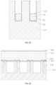
- FIG. 6 is a schematic structural diagram of a base provided in a method of manufacturing a semiconductor structure according to an exemplary embodiment.
- FIG. 7 is a schematic cross-sectional view of the base provided in FIG. 6 along a direction x.
- FIG. 8 is a schematic cross-sectional view of word line trenches of the base provided in FIG. 6 along a direction y.
- FIG. 9 is a schematic diagram of forming a gate dielectric layer in a method of manufacturing a semiconductor structure according to an exemplary embodiment.
- FIG. 10 is a schematic cross-sectional view of FIG. 9 along a direction x.
- FIG. 11 is a schematic cross-sectional view of word line trenches in FIG. 9 along a direction y.
- FIG. 12 is a schematic diagram of forming a barrier layer in a method of manufacturing a semiconductor structure according to an exemplary embodiment.
- FIG. 13 is a schematic cross-sectional view of FIG. 12 along a direction x.
- FIG. 14 is a schematic cross-sectional view of word line trenches in FIG. 12 along a direction y.
- FIG. 15 is a schematic diagram of forming an initial conductive layer in a method of manufacturing a semiconductor structure according to an exemplary embodiment.
- FIG. 16 is a schematic cross-sectional view of FIG. 15 along a direction x.
- FIG. 17 is a schematic cross-sectional view of word line trenches in FIG. 15 along a direction y.
- FIG. 18 is a schematic diagram of forming a conductive layer in a method of manufacturing a semiconductor structure according to an exemplary embodiment.
- FIG. 19 is a schematic cross-sectional view of FIG. 18 along a direction x.
- FIG. 20 is a schematic cross-sectional view of word line trenches in FIG. 18 along a direction y.
- FIG. 21 is a schematic diagram of forming a first isolation structure in a method of manufacturing a semiconductor structure according to an exemplary embodiment.
- FIG. 22 is a schematic cross-sectional view of FIG. 21 along a direction x.
- FIG. 23 is a schematic cross-sectional view of word line trenches in FIG. 21 along a direction y.
- FIG. 24 is a schematic diagram of forming a sacrificial structure in a method of manufacturing a semiconductor structure according to an exemplary embodiment.
- FIG. 25 is a schematic cross-sectional view of FIG. 24 along a direction x.
- FIG. 26 is a schematic cross-sectional view of a second trench in FIG. 24 along a direction y.
- FIG. 27 is a schematic diagram of forming a second isolation structure in a method of manufacturing a semiconductor structure according to an exemplary embodiment.
- FIG. 28 is a schematic cross-sectional view of FIG. 27 along a direction x.
- FIG. 29 is a schematic cross-sectional view of a first trench in FIG. 27 along a direction y.
- FIG. 30 is a schematic diagram of forming a third trench in a method of manufacturing a semiconductor structure according to an exemplary embodiment.
- FIG. 31 is a schematic cross-sectional view of FIG. 30 along a direction x.
- FIG. 32 is a schematic cross-sectional view of a third trench in FIG. 30 along a direction y.
- FIG. 33 is a schematic diagram of forming a fourth trench in a method of manufacturing a semiconductor structure according to an exemplary embodiment.
- FIG. 34 is a schematic cross-sectional view of FIG. 33 along a direction x.
- FIG. 35 is a schematic cross-sectional view of the fourth trench in FIG. 33 along a direction y.
- FIG. 36 is a schematic diagram of forming a word line structure in a method of manufacturing a semiconductor structure according to an exemplary embodiment.
- FIG. 37 is a schematic cross-sectional view of FIG. 36 along a direction x.
- FIG. 38 is a schematic cross-sectional view of the word line structure in FIG. 36 along a direction y.
- FIG. 39 is a schematic diagram of forming a word line structure in a method of manufacturing a semiconductor structure according to an exemplary embodiment.
- FIG. 40 is a schematic cross-sectional view of FIG. 39 along a direction x.
- FIG. 41 is a schematic cross-sectional view of the word line structure in FIG. 39 along a direction y.
- FIG. 42 is a schematic diagram of forming a word line structure in a method of manufacturing a semiconductor structure according to an exemplary embodiment.
- FIG. 43 is a schematic cross-sectional view of FIG. 42 along a direction x.
- FIG. 44 is a schematic diagram of forming a photoresist mask layer on a top surface of a substrate in a method of manufacturing a semiconductor structure according to an exemplary embodiment.
- FIG. 45 is a schematic diagram of projection of a photoresist mask layer on a substrate in a method of manufacturing a semiconductor structure according to an exemplary embodiment.
- FIG. 46 is a schematic diagram of forming a shallow trench in a method of manufacturing a semiconductor structure according to an exemplary embodiment.
- FIG. 47 is a schematic diagram of forming a shallow trench isolation structure in a method of manufacturing a semiconductor structure according to an exemplary embodiment.
- FIG. 48 is a schematic diagram of a projection of a first mask layer formed on a substrate in a method of manufacturing a semiconductor structure according to an exemplary embodiment.
- FIG. 1 is a flowchart of a method of manufacturing a semiconductor structure according to an exemplary embodiment of the present disclosure.
- FIG. 6 to FIG. 38 are schematic diagrams of various stages of the method of manufacturing a semiconductor structure. The method of manufacturing a semiconductor structure is described below with reference to FIG. 6 to FIG. 38 .
- the semiconductor structure is not limited in this embodiment.
- the semiconductor structure is described below by taking a DRAM as an example, but this embodiment is not limited to this.
- the semiconductor structure in this embodiment may be other structures.
- a direction X is an extension direction of an active region 110
- a direction Y is an extension direction of a word line trench 130 .
- the method of manufacturing a semiconductor structure according to the exemplary embodiment of the present disclosure includes the following steps:
- Step S 110 Provide a base, wherein the base includes an active region and a shallow trench isolation structure separating the active region, a word line trench is formed in the base, and the word line trench exposes a part of the active region and the shallow trench isolation structure.
- the providing a base 100 includes the following steps:
- a substrate 101 may be made of a semiconductor material.
- the semiconductor material may be one or more of silicon, germanium, a silicon-germanium compound, and a silicon-carbon compound.
- a photoresist mask layer 103 is formed, and the photoresist mask layer 103 covers a part of a top surface of the substrate 101 .
- a projection of the photoresist mask layer 103 on the substrate 101 includes a plurality of independently arranged mask units 1031 .
- a part of the substrate 101 exposed by the photoresist mask layer 103 is removed through dry or wet etching, as shown in FIG. 46 , to form a shallow trench 102 .
- the photoresist mask layer 103 is removed, a plurality of independently arranged active regions 110 are formed on the substrate 101 covered by the photoresist mask layer 103 , and the plurality of active regions 110 are isolated by shallow trenches 102 .
- a deposition process is used in this embodiment, for example, a chemical vapor deposition process or an atomic layer deposition (ALD) process may be used, a low-k dielectric material is deposited to fill the shallow trench 102 to form a shallow trench isolation structure 120 , and the shallow trench isolation structure 120 separates the plurality of active regions 110 .
- silicon oxide is deposited into the shallow trench 102 to form the shallow trench isolation structure 120 to separate the active region 110 .
- a first mask layer 104 is formed in the active region 110 and on a top surface of the shallow trench isolation structure 120 .
- a projection of the first mask layer 104 on the substrate 101 exposes a part of the active region 110 and a part of the shallow trench isolation structure 120 .
- the part of the active region 110 and the part of the shallow trench isolation structure 120 exposed by the first mask layer 104 are removed, to form the word line trench 130 .
- a depth by which the active region 110 and the shallow trench isolation structure 120 are removed according to the first mask layer 104 is less than a depth of the shallow trench 102 .
- the base 100 includes the active regions 110 and the shallow trench isolation structures 120 , wherein a plurality of active regions 110 are arranged in an array, and the shallow trench isolation structure 120 separates adjacent active regions 110 .
- the shallow trench isolation structure 120 separates the active regions 110 , and the adjacent active regions 110 are independent of each other, to avoid interference between the adjacent active regions 110 .
- Step S 120 Form a first intermediate structure in the word line trench, wherein the first intermediate structure covers side walls and a bottom wall of the word line trench, a first trench is formed in the first intermediate structure, the first intermediate structure includes a sacrificial structure, and the sacrificial structure includes a horizontal portion.
- a first intermediate structure 200 A is an intermediate process structure formed during the formation of a word line structure 200 .
- the first intermediate structure 200 A is a laminated structure and includes a sacrificial structure 250 , and the sacrificial structure 250 includes a horizontal portion 251 .
- the first intermediate structure 200 A forms a first trench 01 in the word line trench 130 , and the horizontal portion 251 of the sacrificial structure 250 serves as a bottom wall of the first trench 01 .
- Step S 130 Remove the horizontal portion of the sacrificial structure, and close the first trench, and form an air chamber.
- the horizontal portion 251 of the sacrificial structure 250 may be removed through an etching process, or the horizontal portion 251 of the sacrificial structure 250 may be removed through plasma reaction release.
- the first trench 01 may be closed by disposition through a chemical vapor deposition (CVD) process or a physical vapor deposition (PVD) process, such that an air chamber 300 is formed at an original position of the horizontal portion 251 of the sacrificial structure 250 .
- CVD chemical vapor deposition
- PVD physical vapor deposition
- an air chamber is formed above a conductive layer, and the existence of the air chamber reduces a parasitic capacitance between conducting wires of the semiconductor structure, reduces the intensity of interference between the conducting wires caused by the parasitic capacitance, and improves electrical performance of the semiconductor structure.
- the method of manufacturing a semiconductor structure according to the exemplary embodiment of the present disclosure includes the following steps:
- step S 210 of this embodiment is implemented in the same manner as step S 110 of the foregoing embodiment, and will not be described in detail again herein.
- Step S 220 Form a second intermediate structure, wherein the second intermediate structure includes a sacrificial structure, and the sacrificial structure forms a second trench.
- a second intermediate structure 200 B is an intermediate process structure formed during the formation of the word line structure 200 .
- the second intermediate structure 200 B is a laminated structure, and the second intermediate structure 200 B includes a sacrificial structure 250 .
- the sacrificial structure 250 includes a horizontal portion 251 and a vertical portion 252 .
- the second intermediate structure 200 B is located in the word line trench 130 , and encloses a second trench 02 in the word line trench 130 .
- the horizontal portion 251 of the sacrificial structure 250 serves as a bottom surface of the second trench 02
- the vertical portion 252 of the sacrificial structure 250 serves as a trench wall of the second trench 02 .
- Step S 230 Deposit a second isolation structure in the second trench, and form a first intermediate structure, wherein the second isolation structure covers a bottom wall and side walls of the second trench, and the second isolation structure forms a first trench.
- the second isolation structure 260 and the second intermediate structure 200 B form the first intermediate structure 200 A
- the first intermediate structure 200 A is an intermediate process structure formed during the formation of the word line structure 200 .
- the second isolation structure 260 may be deposited through an ALD process.
- the second isolation structure 260 covers an inner wall of the second trench 02 .
- the first trench 01 is formed in the second trench 02 .
- a width of the first trench 01 is smaller than a width of the horizontal portion 251 of the sacrificial structure 250 .
- a material of the second isolation structure 260 is different from a material of the sacrificial structure 250 .
- the material of the second isolation structure 260 may be silicon nitride or silicon oxynitride. In this embodiment, the material of the second isolation structure 260 is silicon nitride, and a thickness of the second isolation structure 260 ranges from 2 nm to 4 nm.
- Step S 240 Remove the horizontal portion of the sacrificial structure, and close the first trench, and form an air chamber.
- the horizontal portion 251 of the sacrificial structure 250 may be removed through etching, such that after the first trench 01 is closed, as shown in FIG. 36 or FIG. 39 , the air chamber 300 is formed at an original position of the horizontal portion 251 of the sacrificial structure 250 .
- the semiconductor structure formed in this embodiment undergoes a subsequent manufacturing process to form a bit line structure, a capacitor contact structure, or other conducting wire structures, and an air chamber is located between a conductive layer of a word line structure and the conducting wire structure formed in the subsequent manufacturing process, such that a parasitic capacitance between the word line structure and the conducting wire structure formed in the subsequent manufacturing process can be reduced, thereby preventing the parasitic capacitance from causing mutual interference between conducting wires, and improving electrical performance and stability of the semiconductor structure.
- step S 220 a process of implementing step S 220 in this embodiment is described.
- the forming a second intermediate structure includes the following steps:
- Step S 221 Form a gate dielectric layer, wherein the gate dielectric layer covers the bottom wall and the side walls of the word line trench.
- the gate dielectric layer 210 may be deposited through an ALD process.
- a material of the gate dielectric layer 210 may be silicon oxide, hafnium oxide, lanthanum oxide, or the like.
- Step S 222 Form a conductive layer, wherein the conductive layer covers a bottom wall of the gate dielectric layer, and an upper surface of the conductive layer is lower than an upper surface of the base.
- the process of forming the conductive layer 230 includes the following steps: As shown in FIG. 15 , FIG. 16 , and FIG. 17 , a conductive material is deposited through an ALD process to fill the word line trench 130 and cover the gate dielectric layer 210 to form an initial conductive layer 231 . Then, as shown in FIG. 18 , FIG. 19 , and FIG.
- the initial conductive layer 231 is etched through a dry or wet etching process, the initial conductive layer 231 covering the gate dielectric layer 210 is removed and the initial conductive layer 231 is etched back to a position lower than the top surface of the base 100 , the retained part of the initial conductive layer 231 forms the conductive layer 230 , and an upper part of the conductive layer 230 is retained for forming a space of the air chamber 300 .
- the conductive layer 230 is located at the bottom of the word line trench 130 and covers a bottom wall of the gate dielectric layer 210 .
- the conductive layer 230 exposes a part of side walls of the gate dielectric layer 210 .
- a material of the conductive layer 230 may be one or two or more of a conductive metal, conductive metal nitride, and conductive alloy.
- the material of the conductive layer 230 may be titanium, tantalum, or tungsten.
- the material of the conductive layer 230 is metal tungsten.
- Step S 223 Form a first isolation structure, wherein the first isolation structure covers a top surface of the conductive layer.
- a first isolation structure 240 may be deposited through an ALD process.
- a material of the first isolation structure 240 may be silicon nitride or silicon oxynitride.
- the material of the first isolation structure 240 is silicon nitride, and a thickness of the first isolation structure 240 ranges from 2 nm to 4 nm.
- Step S 224 Deposit the sacrificial structure, and form the second intermediate structure, wherein the sacrificial structure covers a bottom wall and side walls of the first isolation structure.
- a sacrificial material may be deposited through an ALD process, wherein the sacrificial material covers the bottom wall and the side walls of the first isolation structure 240 to form the sacrificial structure 250 .
- a part of the sacrificial structure 250 covering the bottom wall of the first isolation structure 240 is the horizontal portion 251 of the sacrificial structure 250
- a part of the sacrificial structure 250 covering the side walls of the first isolation structure 240 is the vertical portion 252 of the sacrificial structure 250 .
- a material of the sacrificial structure 250 is different from a material of the first isolation structure 240 , such that during removal of the horizontal portion 251 of the sacrificial structure 250 through etching, the horizontal portion 251 of the sacrificial structure 250 can be removed without damaging the first isolation structure 240 by selecting an etch selectivity for etching the sacrificial structure 250 and the first isolation structure 240 .
- the material of the sacrificial structure 250 may be silicon oxide (Silicon monoxide).
- a thickness of the sacrificial structure 250 affects a volume of the air chamber 300 formed in the semiconductor structure.
- the thickness of the sacrificial structure 250 ranges from 4 nm to 6 nm.
- a step of forming a barrier layer 220 through an ALD process is further included.
- the formed barrier layer 220 covers the gate dielectric layer 210 .
- a material of the barrier layer 220 may be titanium nitride.
- the conductive layer 230 is located at the bottom of the word line trench 130 and covers the bottom wall of the gate dielectric layer 210 , and the conductive layer 230 exposes a part of the side walls of the gate dielectric layer 210 .
- the retained initial conductive layer 231 forms the conductive layer 230 .
- the barrier layer 220 is located between the conductive layer 230 and the gate dielectric layer 210 , to prevent the material of the conductive layer 230 from penetrating the base 100 to affect a yield of the semiconductor structure.
- the second intermediate structure formed in this embodiment includes a conductive layer and a sacrificial structure located above the conductive layer, and a horizontal portion of the sacrificial structure and the conductive layer are separated by a first isolation structure.
- An air chamber with a low dielectric constant is formed above the conductive layer of a word line structure by removing the horizontal portion of the sacrificial structure. The air chamber can change electrical performance of an isolation structure located above the conductive layer, and reduce a parasitic capacitance between conducting wires in the semiconductor structure.
- FIG. 4 is a flowchart of a method of manufacturing a semiconductor structure according to an exemplary embodiment of the present disclosure.
- the method of manufacturing a semiconductor structure according to the exemplary embodiment of the present disclosure includes the following steps:
- Step S 310 Provide a base, wherein the base includes an active region and a shallow trench isolation structure separating the active region, a word line trench is formed in the base, and the word line trench exposes a part of the active region and the shallow trench isolation structure.
- Step S 310 of this embodiment is implemented in the same manner as step S 110 of the foregoing embodiment, and will not be described in detail again herein.
- Step S 320 Form a second intermediate structure, wherein the second intermediate structure includes a sacrificial structure, and the sacrificial structure forms a second trench.
- the second intermediate structure 200 B is an intermediate process structure formed during the formation of a word line structure 200 . This is shown in FIG. 25 and FIG. 26 .
- the second intermediate structure 200 B is a laminated structure.
- the second intermediate structure 200 B includes a gate dielectric layer 210 covering a word line trench 130 , a conductive layer 230 covering a bottom wall of the gate dielectric layer 210 and having a top surface lower than a top surface of a base 100 , a barrier layer 220 provided between the conductive layer 230 and the gate dielectric layer 210 , a first isolation structure 240 of the gate dielectric layer 210 that covers a top surface of the conductive layer 230 and that is exposed by the conductive layer 230 , and a sacrificial structure 250 covering the first isolation structure 240 .
- the sacrificial structure 250 includes a horizontal portion 251 and a vertical portion 252 , and the sacrificial structure 250 encloses a second trench 02 in the word line trench 130 .
- the horizontal portion 251 of the sacrificial structure 250 serves as a bottom surface of the second trench 02
- the vertical portion 252 of the sacrificial structure 250 serves as a trench wall of the second trench 02 .
- Step S 330 Deposit a second isolation structure in the second trench, and form a first intermediate structure, wherein the second isolation structure covers a bottom wall and side walls of the second trench, and the second isolation structure forms a first trench.
- a second isolation structure 260 is formed in the second intermediate structure 200 B.
- the second isolation structure 260 covers the sacrificial structure 250 , and the second isolation structure 260 and the second intermediate structure 200 B form a first intermediate structure 200 A.
- a first trench 01 formed by the second isolation structure is narrower than the second trench 02 formed by the sacrificial structure 250 .
- Step S 340 Remove a part of the second isolation structure, and form a third trench, wherein the third trench exposes a part of a horizontal portion of the sacrificial structure.
- a part of a bottom wall of the second isolation structure 260 may be removed by etching through a dry or wet etching process, to expose a part of the horizontal portion 251 of the sacrificial structure 250 , to form a third trench 03 .
- a width of the third trench 03 is smaller than a width of the horizontal portion 251 of the sacrificial structure 250 .
- Step S 350 Remove the horizontal portion of the sacrificial structure, and close the first trench, and form an air chamber.
- the horizontal portion 251 of the sacrificial structure 250 is removed, and a trench communicating with the third trench 03 is formed at an original position of the horizontal portion 251 of the sacrificial structure 250 .
- a filling material is deposited through a CVD process or a PVD process to close the trench, and the deposition process is affected by a shape of an inner wall of the trench, such that the bottom of an original position of the first trench 01 is first closed by the filling material, and a region in the trench not filled by the filling material forms an air chamber 300 .
- a sacrificial structure and a second isolation structure are formed, and then a horizontal portion of the sacrificial structure and a part of the second isolation structure are removed, such that a trench communicating with a third trench is formed at an original position of the horizontal portion of the sacrificial structure, and a deposition process of filling the trench is affected by a shape of an inner wall of the trench, thereby forming a deposition blank above a conductive layer to form an air chamber.
- the air chamber has a low dielectric constant, the existence of the air chamber can reduce a parasitic capacitance between a word line structure and other conducting wires of the semiconductor structure, thereby improving electrical performance and stability of the semiconductor structure.
- FIG. 5 is a flowchart of a method of manufacturing a semiconductor structure according to an exemplary embodiment of the present disclosure.
- the method of manufacturing a semiconductor structure according to the exemplary embodiment of the present disclosure includes the following steps:
- Step S 410 Provide a base, wherein the base includes an active region and a shallow trench isolation structure separating the active region, a word line trench is formed in the base, and the word line trench exposes a part of the active region and the shallow trench isolation structure.
- Step S 420 Form a second intermediate structure, wherein the second intermediate structure includes a sacrificial structure, and the sacrificial structure forms a second trench.
- Step S 430 Deposit a second isolation structure in the second trench, and form a first intermediate structure, wherein the second isolation structure covers a bottom wall and side walls of the second trench, and the second isolation structure forms a first trench.
- Steps S 410 to S 430 of this embodiment are implemented in the same manner as steps S 310 to S 330 of the foregoing embodiment, and will not be described in detail again herein.
- Step S 440 Remove a part of the second isolation structure, and form a third trench, wherein the third trench exposes a part of a horizontal portion of the sacrificial structure.
- a second isolation structure 260 covering the horizontal portion 251 of the sacrificial structure 250 is removed, and form a third trench 03 .
- An etching gas is injected into the first trench 01 . With a top surface of a base 100 as a horizontal direction and an extension direction of the first trench 01 as a vertical direction, an etching speed of the etching gas in the vertical direction is greater than an etching speed of the etching gas in the horizontal direction.
- the etching gas etches and removes the bottom wall of the second isolation structure 260 to expose a part of the horizontal portion 251 of the sacrificial structure 250 , such that a depth of the first trench 01 is increased to form the third trench 03 .
- the etching gas may be one or two or more of sulfur hexafluoride (SF 6 ), carbon tetrafluoride (CF 4 ), chlorine (Cl 2 ), trifluoromethane (CHF 3 ), oxygen (O 2 ), and bromine (Ar) or a gas mixture thereof.
- Step S 450 Inject an etching solution into the third trench, and remove the horizontal portion of the sacrificial structure to form an air layer, wherein the air layer communicates with the third trench to form a fourth trench.
- the horizontal portion 251 of the sacrificial structure 250 is removed to form an air layer 310 .
- the horizontal portion 251 of the sacrificial structure 250 is removed through a wet etching process.
- the etching solution is injected into the third trench 03 .
- the etching solution has a high etch selectivity to a sacrificial material and a second isolation material, and the etching solution has a high etch selectivity to the sacrificial material and a first isolation material.
- a hydrofluoric acid solution is used as the etching solution.
- the hydrofluoric acid solution is injected into the third trench 03 .
- the hydrofluoric acid solution removes the horizontal portion 251 of the sacrificial structure 250 such that the air layer 310 is formed at an original position of the horizontal portion 251 of the sacrificial structure 250 .
- the air layer 310 communicates with the third trench 03 to form a fourth trench 04 .
- a width of the air layer 310 is greater than a width of the third trench 03
- a cross section of the fourth trench 04 is of an “inverted-T” shape.
- Step S 460 Form a third isolation structure, and fill a part of the fourth trench with the third isolation structure, and form an air chamber.
- a third isolation layer material may be deposited through a low pressure chemical vapor deposition (LPCVD) process, to form a third isolation structure 270 .
- the third isolation structure 270 fills a part of the fourth trench 04 , to form a closed air chamber 300 at the bottom of the fourth trench 04 .
- the process of depositing the third isolation layer material to fill the fourth trench 04 is affected by the shape of the inner wall of the fourth trench 04 .
- the third isolation layer material first closes the bottom of the third trench 03 , and form a closed air chamber 300 at the bottom of the fourth trench 04 .
- the air chamber 300 includes at least an air layer 310 (referring to FIG. 36 ) formed by removing the horizontal portion 251 of the sacrificial structure 250 .
- the air chamber 300 may further includes a part of the third trench 03 (referring to FIG. 39 or FIG. 41 ).
- the third isolation structure 270 and the first intermediate structure 200 A form a word line structure 200 .
- the air chamber 300 closed and disposed above the conductive layer 230 is formed in the word line structure 200 .
- a horizontal portion of a sacrificial structure is etched and removed by using an etching reagent, to form, in a word line trench, a fourth trench with a cross section of an “inverted-T” shape, such that an air chamber is formed at the bottom of the fourth trench during filling of the fourth trench because the filling process is affected by a shape of an inner wall of the fourth trench, and in a finally formed semiconductor structure, the air chamber is formed above a conductive layer of the word line structure.
- the air of a low dielectric constant reduces electrical performance of an isolation structure above the conductive layer, thereby further reducing a parasitic capacitance between the word line structure of the semiconductor structure and other conducting wire structures.
- the semiconductor structure includes: a base 100 , a word line trench 130 formed in the base 100 , and a word line structure 200 formed in the word line trench 130 .
- the base 100 includes active regions 110 and shallow trench isolation structures 120 separating the active regions 110 .
- the word line trench 130 intersects the active region 110 and the shallow trench isolation structure 120 .
- the word line structure 200 includes a conductive layer 230 , a top isolation structure 280 , and an air chamber 300 .
- the air chamber 300 is provided between the conductive layer 230 and the top isolation structure 280 .
- an air chamber 300 is provided between the conductive layer 230 of the word line structure 200 and the top isolation structure 280 above.
- the existence of the air chamber 300 changes electrical features of the top isolation structure 280 , thereby reducing a parasitic capacitance between the word line structure 200 and other conducting wires of the semiconductor structure, reducing capacitive interference between conductive structures of the semiconductor structure, and improving electrical performance and stability of the semiconductor structure.
- the word line structure 200 further includes a gate dielectric layer 210 and a first isolation structure 240 .
- the gate dielectric layer 210 covers a bottom wall and side walls of the word line trench 130 .
- the first isolation structure 240 covers a top surface of the conductive layer 230 and side walls of the gate dielectric layer 210 exposed by the conductive layer 230 .
- the air chamber 300 is provided between the top isolation structure 280 and the first isolation structure 240 .
- the top isolation structure 280 includes a second isolation structure 260 and a third isolation structure 270 , and the air chamber 300 is formed between a bottom surface of the third isolation structure 270 and the first isolation structure 240 .
- the bottom surface of the third isolation structure 270 and a bottom surface of the second isolation structure 260 are at a same height, and a height of the formed air chamber 300 is equal to a height of the bottom surface of the second isolation structure 260 .
- the bottom surface of the third isolation structure 270 is higher than the bottom surface of the second isolation structure 260 .
- the bottom surface of the third isolation structure 270 is higher than the bottom surface of the second isolation structure 260 , and a cross section of the formed air chamber 300 is of an “inverted-T” shape structure.
- the bottom surface of the third isolation structure 270 is higher than the bottom surface of the second isolation structure 260 , and a cross section of the formed air chamber 300 is of an irregular structure.
- a ratio of a width of the third isolation structure 270 to a width of the word line trench 130 ranges from 0.1 to 0.3.
- bit line structure 200 includes a sacrificial structure 250 , the sacrificial structure 250 covers side walls of the first isolation structure 240 , the sacrificial structure 250 is provided between the side walls of the first isolation structure 240 and the second isolation structure 260 , and the second isolation structure 260 covers the sacrificial structure 250 .
- most content of the bit line structure in this embodiment is the same as that in the foregoing embodiment, and a difference between this embodiment and the foregoing embodiment lies in that, as shown in FIG. 36 , or FIG. 39 , or FIG. 41 , the word line structure 200 further includes a barrier layer 220 , and the barrier layer 220 is provided between the conductive layer 230 and the gate dielectric layer 210 , to prevent a material of the conductive layer 230 from penetrating the base 100 to contaminate the base 100 and affect performance of the semiconductor structure.
- the air chamber 300 is provided between the conductive layer 230 and the top isolation structure 280 of the word line structure 200 , and the existence of the air chamber 300 affects electrical performance of the top isolation structure 280 , thereby further reducing a parasitic capacitance between the word line structure 200 and other conducting wire structures of the semiconductor structure, and improving electrical performance and stability of the semiconductor structure.
- an air chamber is formed above a conductive layer of the semiconductor structure, thereby reducing a parasitic capacitance between conducting wires of the semiconductor structure, reducing interference between the conducting wires caused by the parasitic capacitance, and improving electrical performance and stability of the semiconductor structure.
Landscapes
- Engineering & Computer Science (AREA)
- Manufacturing & Machinery (AREA)
- Physics & Mathematics (AREA)
- Condensed Matter Physics & Semiconductors (AREA)
- General Physics & Mathematics (AREA)
- Computer Hardware Design (AREA)
- Microelectronics & Electronic Packaging (AREA)
- Power Engineering (AREA)
- Semiconductor Memories (AREA)
- Element Separation (AREA)
Abstract
Description
Claims (10)
Applications Claiming Priority (3)
| Application Number | Priority Date | Filing Date | Title |
|---|---|---|---|
| CN202110918051.2A CN113644032B (en) | 2021-08-11 | 2021-08-11 | Method for manufacturing semiconductor structure and semiconductor structure |
| CN202110918051.2 | 2021-08-11 | ||
| PCT/CN2021/116921 WO2023015641A1 (en) | 2021-08-11 | 2021-09-07 | Semiconductor structure manufacturing method and semiconductor structure |
Related Parent Applications (1)
| Application Number | Title | Priority Date | Filing Date |
|---|---|---|---|
| PCT/CN2021/116921 Continuation WO2023015641A1 (en) | 2021-08-11 | 2021-09-07 | Semiconductor structure manufacturing method and semiconductor structure |
Publications (2)
| Publication Number | Publication Date |
|---|---|
| US20230047893A1 US20230047893A1 (en) | 2023-02-16 |
| US12183622B2 true US12183622B2 (en) | 2024-12-31 |
Family
ID=85178208
Family Applications (1)
| Application Number | Title | Priority Date | Filing Date |
|---|---|---|---|
| US17/652,338 Active 2042-09-09 US12183622B2 (en) | 2021-08-11 | 2022-02-24 | Semiconductor structure comprising an air chamber and method of manufacturing the same |
Country Status (1)
| Country | Link |
|---|---|
| US (1) | US12183622B2 (en) |
Citations (12)
| Publication number | Priority date | Publication date | Assignee | Title |
|---|---|---|---|---|
| US20140291755A1 (en) * | 2013-04-01 | 2014-10-02 | Sung-Kweon Baek | Semiconductor device and semiconductor module |
| US20160104798A1 (en) * | 2014-10-10 | 2016-04-14 | SK Hynix Inc. | Vertical-channel semiconductor device |
| US20160181377A1 (en) * | 2014-12-16 | 2016-06-23 | SK Hynix Inc. | Semiconductor device having dual work function gate structure, method for fabricating the same, memory cell having the same, and electronic device having the same |
| CN108063140A (en) | 2017-11-27 | 2018-05-22 | 睿力集成电路有限公司 | Transistor arrangement, memory cell array and preparation method thereof |
| US20180145080A1 (en) * | 2016-11-18 | 2018-05-24 | Samsung Electronics Co., Ltd. | Semiconductor device and method for fabricating the same |
| US20200203351A1 (en) | 2018-12-20 | 2020-06-25 | Samsung Electronics Co., Ltd. | Memory device |
| CN111430348A (en) | 2020-04-14 | 2020-07-17 | 福建省晋华集成电路有限公司 | Memory and method of forming the same |
| TWI717173B (en) | 2019-12-26 | 2021-01-21 | 華邦電子股份有限公司 | Memory devices and methods for forming the same |
| CN112885833A (en) | 2019-11-29 | 2021-06-01 | 长鑫存储技术有限公司 | Semiconductor device and method for manufacturing the same |
| US11056175B1 (en) | 2020-07-28 | 2021-07-06 | Winbond Electronics Corp. | Semiconductor device and manufacturing method thereof |
| US20210242211A1 (en) * | 2020-02-05 | 2021-08-05 | Nanya Technology Corporation | Semiconductor device having buried word line and method of manufacturing the same |
| US20220223601A1 (en) * | 2021-01-12 | 2022-07-14 | Winbond Electronics Corp. | Semiconductor structure and method for forming the same |
-
2022
- 2022-02-24 US US17/652,338 patent/US12183622B2/en active Active
Patent Citations (12)
| Publication number | Priority date | Publication date | Assignee | Title |
|---|---|---|---|---|
| US20140291755A1 (en) * | 2013-04-01 | 2014-10-02 | Sung-Kweon Baek | Semiconductor device and semiconductor module |
| US20160104798A1 (en) * | 2014-10-10 | 2016-04-14 | SK Hynix Inc. | Vertical-channel semiconductor device |
| US20160181377A1 (en) * | 2014-12-16 | 2016-06-23 | SK Hynix Inc. | Semiconductor device having dual work function gate structure, method for fabricating the same, memory cell having the same, and electronic device having the same |
| US20180145080A1 (en) * | 2016-11-18 | 2018-05-24 | Samsung Electronics Co., Ltd. | Semiconductor device and method for fabricating the same |
| CN108063140A (en) | 2017-11-27 | 2018-05-22 | 睿力集成电路有限公司 | Transistor arrangement, memory cell array and preparation method thereof |
| US20200203351A1 (en) | 2018-12-20 | 2020-06-25 | Samsung Electronics Co., Ltd. | Memory device |
| CN112885833A (en) | 2019-11-29 | 2021-06-01 | 长鑫存储技术有限公司 | Semiconductor device and method for manufacturing the same |
| TWI717173B (en) | 2019-12-26 | 2021-01-21 | 華邦電子股份有限公司 | Memory devices and methods for forming the same |
| US20210242211A1 (en) * | 2020-02-05 | 2021-08-05 | Nanya Technology Corporation | Semiconductor device having buried word line and method of manufacturing the same |
| CN111430348A (en) | 2020-04-14 | 2020-07-17 | 福建省晋华集成电路有限公司 | Memory and method of forming the same |
| US11056175B1 (en) | 2020-07-28 | 2021-07-06 | Winbond Electronics Corp. | Semiconductor device and manufacturing method thereof |
| US20220223601A1 (en) * | 2021-01-12 | 2022-07-14 | Winbond Electronics Corp. | Semiconductor structure and method for forming the same |
Non-Patent Citations (1)
| Title |
|---|
| International Search Report cited in PCT/CN2021/116921 mailed May 6, 2022, 8 pages. |
Also Published As
| Publication number | Publication date |
|---|---|
| US20230047893A1 (en) | 2023-02-16 |
Similar Documents
| Publication | Publication Date | Title |
|---|---|---|
| US9412665B2 (en) | Semiconductor device and method of fabricating the same | |
| US7368365B2 (en) | Memory array buried digit line | |
| CN108573926B (en) | Semiconductor memory device and method of manufacturing the same | |
| TWI469323B (en) | Vertical channel transistor array and manufacturing method thereof | |
| US11908797B2 (en) | Integrated circuit device having a bit line and a main insulating spacer with an extended portion | |
| CN112992792B (en) | Method for manufacturing semiconductor structure and semiconductor structure | |
| US12419042B2 (en) | Integrated circuit device | |
| CN109427786B (en) | Semiconductor memory device and manufacturing process thereof | |
| CN113644032B (en) | Method for manufacturing semiconductor structure and semiconductor structure | |
| CN113707612A (en) | Memory device and method of forming the same | |
| KR20220073231A (en) | Semiconductor devices | |
| US12150291B2 (en) | Semiconductor memory device | |
| CN113594097B (en) | Buried bit line structure, manufacturing method thereof and semiconductor structure | |
| US12183622B2 (en) | Semiconductor structure comprising an air chamber and method of manufacturing the same | |
| US12114484B2 (en) | Buried bit line structure, manufacturing method thereof, and semiconductor structure | |
| US20230389301A1 (en) | Method of manufacturing semiconductor structure and semiconductor structure | |
| US20230065654A1 (en) | Semiconductor structure and method for forming semiconductor structure | |
| US20230187482A1 (en) | Method of manufacturing semiconductor structure and semiconductor structure | |
| WO2023029392A1 (en) | Semiconductor structure and formation method therefor | |
| JP2006191053A (en) | Manufacturing method of semiconductor memory device | |
| CN119383948B (en) | Semiconductor structure and method for manufacturing the same | |
| CN121335097A (en) | Semiconductor structure and manufacturing method thereof | |
| CN115223946A (en) | A semiconductor memory device and its manufacturing method |
Legal Events
| Date | Code | Title | Description |
|---|---|---|---|
| AS | Assignment |
Owner name: CHANGXIN MEMORY TECHNOLOGIES, INC., CHINA Free format text: ASSIGNMENT OF ASSIGNORS INTEREST;ASSIGNOR:LU, JINGWEN;REEL/FRAME:059090/0343 Effective date: 20210806 |
|
| FEPP | Fee payment procedure |
Free format text: ENTITY STATUS SET TO UNDISCOUNTED (ORIGINAL EVENT CODE: BIG.); ENTITY STATUS OF PATENT OWNER: LARGE ENTITY |
|
| STPP | Information on status: patent application and granting procedure in general |
Free format text: DOCKETED NEW CASE - READY FOR EXAMINATION |
|
| STPP | Information on status: patent application and granting procedure in general |
Free format text: NON FINAL ACTION MAILED |
|
| STPP | Information on status: patent application and granting procedure in general |
Free format text: RESPONSE TO NON-FINAL OFFICE ACTION ENTERED AND FORWARDED TO EXAMINER |
|
| STPP | Information on status: patent application and granting procedure in general |
Free format text: AWAITING TC RESP., ISSUE FEE NOT PAID |
|
| STPP | Information on status: patent application and granting procedure in general |
Free format text: NOTICE OF ALLOWANCE MAILED -- APPLICATION RECEIVED IN OFFICE OF PUBLICATIONS |
|
| STPP | Information on status: patent application and granting procedure in general |
Free format text: PUBLICATIONS -- ISSUE FEE PAYMENT VERIFIED |
|
| STCF | Information on status: patent grant |
Free format text: PATENTED CASE |