US12180233B2 - Metal complexes - Google Patents
Metal complexes Download PDFInfo
- Publication number
- US12180233B2 US12180233B2 US16/969,584 US201916969584A US12180233B2 US 12180233 B2 US12180233 B2 US 12180233B2 US 201916969584 A US201916969584 A US 201916969584A US 12180233 B2 US12180233 B2 US 12180233B2
- Authority
- US
- United States
- Prior art keywords
- group
- formula
- carbon atoms
- groups
- radicals
- Prior art date
- Legal status (The legal status is an assumption and is not a legal conclusion. Google has not performed a legal analysis and makes no representation as to the accuracy of the status listed.)
- Active, expires
Links
Classifications
-
- C—CHEMISTRY; METALLURGY
- C07—ORGANIC CHEMISTRY
- C07F—ACYCLIC, CARBOCYCLIC OR HETEROCYCLIC COMPOUNDS CONTAINING ELEMENTS OTHER THAN CARBON, HYDROGEN, HALOGEN, OXYGEN, NITROGEN, SULFUR, SELENIUM OR TELLURIUM
- C07F15/00—Compounds containing elements of Groups 8, 9, 10 or 18 of the Periodic Table
- C07F15/0006—Compounds containing elements of Groups 8, 9, 10 or 18 of the Periodic Table compounds of the platinum group
- C07F15/0033—Iridium compounds
-
- C—CHEMISTRY; METALLURGY
- C09—DYES; PAINTS; POLISHES; NATURAL RESINS; ADHESIVES; COMPOSITIONS NOT OTHERWISE PROVIDED FOR; APPLICATIONS OF MATERIALS NOT OTHERWISE PROVIDED FOR
- C09K—MATERIALS FOR MISCELLANEOUS APPLICATIONS, NOT PROVIDED FOR ELSEWHERE
- C09K11/00—Luminescent materials, e.g. electroluminescent or chemiluminescent
- C09K11/06—Luminescent materials, e.g. electroluminescent or chemiluminescent containing organic luminescent materials
-
- H—ELECTRICITY
- H10—SEMICONDUCTOR DEVICES; ELECTRIC SOLID-STATE DEVICES NOT OTHERWISE PROVIDED FOR
- H10K—ORGANIC ELECTRIC SOLID-STATE DEVICES
- H10K85/00—Organic materials used in the body or electrodes of devices covered by this subclass
- H10K85/30—Coordination compounds
- H10K85/341—Transition metal complexes, e.g. Ru(II)polypyridine complexes
- H10K85/342—Transition metal complexes, e.g. Ru(II)polypyridine complexes comprising iridium
-
- C—CHEMISTRY; METALLURGY
- C09—DYES; PAINTS; POLISHES; NATURAL RESINS; ADHESIVES; COMPOSITIONS NOT OTHERWISE PROVIDED FOR; APPLICATIONS OF MATERIALS NOT OTHERWISE PROVIDED FOR
- C09K—MATERIALS FOR MISCELLANEOUS APPLICATIONS, NOT PROVIDED FOR ELSEWHERE
- C09K2211/00—Chemical nature of organic luminescent or tenebrescent compounds
- C09K2211/10—Non-macromolecular compounds
- C09K2211/1018—Heterocyclic compounds
- C09K2211/1025—Heterocyclic compounds characterised by ligands
- C09K2211/1029—Heterocyclic compounds characterised by ligands containing one nitrogen atom as the heteroatom
-
- C—CHEMISTRY; METALLURGY
- C09—DYES; PAINTS; POLISHES; NATURAL RESINS; ADHESIVES; COMPOSITIONS NOT OTHERWISE PROVIDED FOR; APPLICATIONS OF MATERIALS NOT OTHERWISE PROVIDED FOR
- C09K—MATERIALS FOR MISCELLANEOUS APPLICATIONS, NOT PROVIDED FOR ELSEWHERE
- C09K2211/00—Chemical nature of organic luminescent or tenebrescent compounds
- C09K2211/10—Non-macromolecular compounds
- C09K2211/1018—Heterocyclic compounds
- C09K2211/1025—Heterocyclic compounds characterised by ligands
- C09K2211/1059—Heterocyclic compounds characterised by ligands containing three nitrogen atoms as heteroatoms
-
- C—CHEMISTRY; METALLURGY
- C09—DYES; PAINTS; POLISHES; NATURAL RESINS; ADHESIVES; COMPOSITIONS NOT OTHERWISE PROVIDED FOR; APPLICATIONS OF MATERIALS NOT OTHERWISE PROVIDED FOR
- C09K—MATERIALS FOR MISCELLANEOUS APPLICATIONS, NOT PROVIDED FOR ELSEWHERE
- C09K2211/00—Chemical nature of organic luminescent or tenebrescent compounds
- C09K2211/10—Non-macromolecular compounds
- C09K2211/1018—Heterocyclic compounds
- C09K2211/1025—Heterocyclic compounds characterised by ligands
- C09K2211/1088—Heterocyclic compounds characterised by ligands containing oxygen as the only heteroatom
-
- C—CHEMISTRY; METALLURGY
- C09—DYES; PAINTS; POLISHES; NATURAL RESINS; ADHESIVES; COMPOSITIONS NOT OTHERWISE PROVIDED FOR; APPLICATIONS OF MATERIALS NOT OTHERWISE PROVIDED FOR
- C09K—MATERIALS FOR MISCELLANEOUS APPLICATIONS, NOT PROVIDED FOR ELSEWHERE
- C09K2211/00—Chemical nature of organic luminescent or tenebrescent compounds
- C09K2211/10—Non-macromolecular compounds
- C09K2211/1018—Heterocyclic compounds
- C09K2211/1025—Heterocyclic compounds characterised by ligands
- C09K2211/1092—Heterocyclic compounds characterised by ligands containing sulfur as the only heteroatom
-
- C—CHEMISTRY; METALLURGY
- C09—DYES; PAINTS; POLISHES; NATURAL RESINS; ADHESIVES; COMPOSITIONS NOT OTHERWISE PROVIDED FOR; APPLICATIONS OF MATERIALS NOT OTHERWISE PROVIDED FOR
- C09K—MATERIALS FOR MISCELLANEOUS APPLICATIONS, NOT PROVIDED FOR ELSEWHERE
- C09K2211/00—Chemical nature of organic luminescent or tenebrescent compounds
- C09K2211/18—Metal complexes
- C09K2211/185—Metal complexes of the platinum group, i.e. Os, Ir, Pt, Ru, Rh or Pd
-
- H—ELECTRICITY
- H10—SEMICONDUCTOR DEVICES; ELECTRIC SOLID-STATE DEVICES NOT OTHERWISE PROVIDED FOR
- H10K—ORGANIC ELECTRIC SOLID-STATE DEVICES
- H10K2101/00—Properties of the organic materials covered by group H10K85/00
- H10K2101/10—Triplet emission
-
- H—ELECTRICITY
- H10—SEMICONDUCTOR DEVICES; ELECTRIC SOLID-STATE DEVICES NOT OTHERWISE PROVIDED FOR
- H10K—ORGANIC ELECTRIC SOLID-STATE DEVICES
- H10K2101/00—Properties of the organic materials covered by group H10K85/00
- H10K2101/90—Multiple hosts in the emissive layer
-
- H—ELECTRICITY
- H10—SEMICONDUCTOR DEVICES; ELECTRIC SOLID-STATE DEVICES NOT OTHERWISE PROVIDED FOR
- H10K—ORGANIC ELECTRIC SOLID-STATE DEVICES
- H10K50/00—Organic light-emitting devices
- H10K50/10—OLEDs or polymer light-emitting diodes [PLED]
- H10K50/11—OLEDs or polymer light-emitting diodes [PLED] characterised by the electroluminescent [EL] layers
Definitions
- the present invention relates to iridium complexes suitable for use in organic electroluminescent devices, especially as emitters.
- triplet emitters used in phosphorescent organic electroluminescent devices are, in particular, bis- and tris-ortho-metallated iridium complexes having aromatic ligands, where the ligands bind to the metal via a negatively charged carbon atom and an uncharged nitrogen atom or via a negatively charged carbon atom and an uncharged carbene carbon atom.
- complexes examples include tris(phenylpyridyl)iridium(III) and derivatives thereof, and a multitude of related complexes, for example with 1- or 3-phenylisoquinoline ligands, with 2-phenylquinoline ligands or with phenylcarbene ligands, where these complexes may also have acetylacetonate as auxiliary ligand.
- Complexes of this kind are also known with polypodal ligands, as described, for example, in U.S. Pat. No. 7,332,232 and WO 2016/124304.
- the problem addressed by the present invention is therefore that of providing novel and especially improved metal complexes suitable as emitters for use in OLEDs.
- the invention thus provides a compound of the formula (1)
- the ligand is thus a hexadentate tripodal ligand having the three bidentate sub-ligands L 1 , L 2 and L 3 .
- “Bidentate” means that the particular sub-ligand in the complex coordinates or binds to the iridium via two coordination sites.
- “Tripodal” means that the ligand has three sub-ligands bonded to the bridge V or the bridge of the formula (2). Since the ligand has three bidentate sub-ligands, the overall result is a hexadentate ligand, i.e. a ligand which coordinates or binds to the iridium via six coordination sites.
- V 2 —CR 2 —SiR 2 —, —CR 2 —O— or —CR 2 —NR—, where, in this case, the silicon or the oxygen or nitrogen binds either to the central cycle or to the bidentate sub-ligand.
- the bond of the ligand to the iridium may either be a coordinate bond or a covalent bond, or the covalent fraction of the bond may vary according to the ligand.
- the ligand or the sub-ligand coordinates or binds to the iridium this refers in the context of the present application to any kind of bond from the ligand or sub-ligand to the iridium, irrespective of the covalent component of the bond.
- R or R 1 radicals When two R or R 1 radicals together form a ring system, it may be mono- or polycyclic, and aliphatic, heteroaliphatic, aromatic or heteroaromatic. In this case, these radicals which together form a ring system may be adjacent, meaning that these radicals are bonded to the same carbon atom or to carbon atoms directly bonded to one another, or they may be further removed from one another. For example, it is also possible for an R radical bonded to the X 2 group to form a ring with an R radical bonded to the X 1 group.
- this kind of ring formation is possible in radicals bonded to carbon atoms directly adjacent to one another, or in radicals bonded to further-removed carbon atoms. Preference is given to this kind of ring formation in radicals bonded to carbon atoms directly bonded to one another.
- An aryl group in the context of this invention contains 6 to 40 carbon atoms; a heteroaryl group in the context of this invention contains 2 to 40 carbon atoms and at least one heteroatom, with the proviso that the sum total of carbon atoms and heteroatoms is at least 5.
- the heteroatoms are preferably selected from N, O and/or S.
- the heteroaryl group in this case preferably contains not more than three heteroatoms.
- An aryl group or heteroaryl group is understood here to mean either a simple aromatic cycle, i.e.
- benzene or a simple heteroaromatic cycle, for example pyridine, pyrimidine, thiophene, etc., or a fused aryl or heteroaryl group, for example naphthalene, anthracene, phenanthrene, quinoline, isoquinoline, etc.
- An aromatic ring system in the context of this invention contains 6 to 40 carbon atoms in the ring system.
- a heteroaromatic ring system in the context of this invention contains 1 to 40 carbon atoms and at least one heteroatom in the ring system, with the proviso that the sum total of carbon atoms and heteroatoms is at least 5.
- the heteroatoms are preferably selected from N, O and/or S.
- An aromatic or heteroaromatic ring system in the context of this invention shall be understood to mean a system which does not necessarily contain only aryl or heteroaryl groups, but in which it is also possible for a plurality of aryl or heteroaryl groups to be interrupted by a nonaromatic unit (preferably less than 10% of the atoms other than H), for example a carbon, nitrogen or oxygen atom or a carbonyl group.
- a nonaromatic unit preferably less than 10% of the atoms other than H
- systems such as 9,9′-spirobifluorene, 9,9-diarylfluorene, triarylamine, diaryl ethers, stilbene, etc.
- a cyclic alkyl, alkoxy or thioalkoxy group in the context of this invention is understood to mean a monocyclic, bicyclic or polycyclic group.
- a C 1 - to C 20 -alkyl group in which individual hydrogen atoms or CH 2 groups may also be replaced by the abovementioned groups is understood to mean, for example, the methyl, ethyl, n-propyl, i-propyl, cyclopropyl, n-butyl, i-butyl, s-butyl, t-butyl, cyclobutyl, 2-methylbutyl, n-pentyl, s-pentyl, t-pentyl, 2-pentyl, neopentyl, cyclopentyl, n-hexyl, s-hexyl, t-hexyl, 2-hexyl, 3-hexyl, neohexyl, cyclohexyl, 1-methylcyclopentyl, 2-methylpentyl, n-heptyl, 2-heptyl, 3-h
- alkenyl group is understood to mean, for example, ethenyl, propenyl, butenyl, pentenyl, cyclopentenyl, hexenyl, cyclohexenyl, heptenyl, cycloheptenyl, octenyl, cyclooctenyl or cyclooctadienyl.
- An alkynyl group is understood to mean, for example, ethynyl, propynyl, butynyl, pentynyl, hexynyl, heptynyl or octynyl.
- OR 1 group is understood to mean, for example, methoxy, trifluoromethoxy, ethoxy, n-propoxy, i-propoxy, n-butoxy, i-butoxy, s-butoxy, t-butoxy or 2-methylbutoxy.
- An aromatic or heteroaromatic ring system which has 5-40 aromatic ring atoms and may also be substituted in each case by the abovementioned radicals and which may be joined to the aromatic or heteroaromatic system via any desired positions is understood to mean, for example, groups derived from benzene, naphthalene, anthracene, benzanthracene, phenanthrene, benzophenanthrene, pyrene, chrysene, perylene, fluoranthene, benzofluoranthene, naphthacene, pentacene, benzopyrene, biphenyl, biphenylene, terphenyl, terphenylene, fluorene, spirobifluorene, dihydrophenanthrene, dihydropyrene, tetrahydropyrene, cis- or trans-indenofluorene, cis- or trans-monobenzoindenofluorene, cis
- bridgehead V i.e. the structure of the formula (2).
- all X 1 groups in the group of the formula (2) are CR, and so the central trivalent cycle of the formula (2) is a benzene. More preferably, all X 1 groups are CH or CD, especially CH. In a further preferred embodiment of the invention, all X 1 groups are a nitrogen atom, and so the central trivalent cycle of the formula (2) is a triazine.
- Preferred embodiments of the group of the formula (1) are the structures of the following formula (4) or (5):
- Preferred R radicals on the trivalent central benzene ring of the formula (4) are as follows:
- the group of the formula (4) is a structure of the following formula (4′):
- V 1 and the groups of the formula (3) as occur in the group of the formulae (2), (4) and (5).
- V 3 is a group of the formula (3)
- the preferences which follow are applicable to this group as well.
- these structures contain one or two ortho-bonded bivalent arylene or heteroarylene units according to whether V 3 is a group of the formula (3) or is a group selected from —CR 2 —CR 2 —, —CR 2 —SiR 2 —, —CR 2 —O— and —CR 2 —NR—.
- the symbol X 3 in the group of the formula (3) is C, and so the group of the formula (3) is represented by the following formula (3a):
- the group of the formula (3) may represent a heteroaromatic five-membered ring or an aromatic or heteroaromatic six-membered ring.
- the group of the formula (3) contains not more than two heteroatoms in the aryl or heteroaryl group, more preferably not more than one heteroatom. This does not mean that any substituents bonded to this group cannot also contain heteroatoms. In addition, this definition does not mean that formation of rings by substituents cannot give rise to fused aromatic or heteroaromatic structures, for example naphthalene, benzimidazole, etc.
- Suitable groups of the formula (3) are benzene, pyridine, pyrimidine, pyrazine, pyridazine, pyrrole, furan, thiophene, pyrazole, imidazole, oxazole and thiazole.
- the V 2 group and optionally V 3 is selected from the —CR 2 —CR 2 — and —CR 2 —O— groups.
- V 2 or V 3 is a —CR 2 —O— group
- the oxygen atom may either be bonded to the central cycle of the group of the formula (2), or it may be bonded to the sub-ligands L 2 or L 3 .
- V 2 is —CR 2 —CR 2 —.
- V 3 is also —CR 2 —CR 2 —, these groups may be the same or different. They are preferably the same.
- R radicals on the —CR 2 —CR 2 — or —CR 2 —O— group are selected from the group consisting of H, D, F and an alkyl group having 1 to 5 carbon atoms, where hydrogen atoms may also be replaced by D or F and where adjacent R together may form a ring system.
- Particularly preferred R radicals on these groups are selected from H, D, CH 3 and CD 3 , or two R radicals bonded to the same carbon atom, together with the carbon atom to which they are bonded, form a cyclopentane or cyclohexane ring.
- the structures of the formula (4) and (5) are selected from the structures of the following formulae (4a) to (5b):
- a preferred embodiment of the formulae (4a) and (4b) are the structures of the following formulae (4a′) and (4b′):
- R groups in the formulae (3) to (5) are the same or different at each instance and are H, D or an alkyl group having 1 to 4 carbon atoms. Most preferably, R ⁇ H or D, especially H.
- Particularly preferred embodiments of the formula (2) are therefore the structures of the following formulae (4c), (4d), (4e), (4f), (5c), (5d), (5e) and (5f):
- L 1 , L 2 and L 3 coordinate to the iridium via one carbon atom and one nitrogen atom, via two carbon atoms, via two nitrogen atoms, via two oxygen atoms, or via one nitrogen atom and one oxygen atom.
- at least one of the sub-ligands L 1 , L 2 and L 3 more preferably at least two of the sub-ligands L 1 , L 2 and L 3 , coordinate(s) to the iridium via one carbon atom and one nitrogen atom or via two carbon atoms, especially via one carbon atom and one nitrogen atom.
- all three sub-ligands L 1 , L 2 and L 3 each have one carbon atom and one nitrogen atom as coordinating atoms.
- the metallacycle which is formed from the iridium and the sub-ligand L 1 , L 2 or L 3 is a five-membered ring. This is especially true when the coordinating atoms are carbon and nitrogen or two carbons or nitrogen and oxygen. If the two coordinating atoms are nitrogen or oxygen, the formation of a six-membered ring may also be preferred.
- the formation of a five-membered ring is shown in schematic form below:
- N is a coordinating nitrogen atom and C is a coordinating carbon atom
- the carbon atoms shown are atoms of the sub-ligand L 1 , L 2 or L 3 .
- At least one of the sub-ligands L 1 , L 2 and L 3 , more preferably at least two sub-ligands L 1 , L 2 and L 3 and most preferably all three sub-ligands L 1 , L 2 and L 3 are the same or different at each instance and are a structure of one of the following formulae (L-1) and (L-2):
- CyD preferably coordinates via an uncharged nitrogen atom or via a carbene carbon atom.
- CyC coordinates via an anionic carbon atom.
- a ring system When two or more of the substituents, especially two or more R radicals, together form a ring system, it is possible for a ring system to be formed from substituents bonded to directly adjacent carbon atoms. In addition, it is also possible that the substituents on CyC and CyD together form a ring, as a result of which CyC and CyD may also together form a single fused aryl or heteroaryl group as bidentate sub-ligand.
- all sub-ligands L 1 , L 2 and L 3 to have a structure of the formula (L-1), so as to form a pseudo-facial complex, or for all sub-ligands L 1 , L 2 and L 3 to have a structure of the formula (L-2), so as to form a pseudo-facial complex, or for one or two of the sub-ligands L 1 , L 2 and L 3 to have a structure of the formula (L-1) and the other sub-ligands to have a structure (L-2), so as to form a pseudo-meridional complex.
- CyC is an aryl or heteroaryl group having 6 to 13 aromatic ring atoms, more preferably having 6 to 10 aromatic ring atoms, most preferably having 6 aromatic ring atoms, which coordinates to the metal via a carbon atom, which may be substituted by one or more R radicals and which is bonded to CyD via a covalent bond.
- CyC group are the structures of the following formulae (CyC-1) to (CyC-20) where the CyC group binds in each case at the position signified by # to CyD and coordinates at the position signified by * to the iridium,
- a total of not more than two symbols X in CyC are N, more preferably not more than one symbol X in CyC is N, and most preferably all symbols X are CR, with the proviso that, when the bridge V or the bridge of the formula (2) is bonded to CyC, one symbol X is C and the bridge V or the bridge of the formula (2) is bonded to this carbon atom.
- CyC groups are the groups of the following formulae (CyC-1a) to (CyC-20a):
- Preferred groups among the (CyC-1) to (CyC-20) groups are the (CyC-1), (CyC-3), (CyC-8), (CyC-10), (CyC-12), (CyC-13) and (CyC-16) groups, and particular preference is given to the (CyC-1a), (CyC-3a), (CyC-8a), (CyC-10a), (CyC-12a), (CyC-13a) and (CyC-16a) groups.
- CyD is a heteroaryl group having 5 to 13 aromatic ring atoms, more preferably having 6 to 10 aromatic ring atoms, which coordinates to the metal via an uncharged nitrogen atom or via a carbene carbon atom and which may be substituted by one or more R radicals and which is bonded via a covalent bond to CyC.
- CyD group are the structures of the following formulae (CyD-1) to (CyD-12) where the CyD group binds in each case at the position signified by # to CyC and coordinates at the position signified by * to the iridium,
- X, W and R have the definitions given above, with the proviso that, when the bridge V or the bridge of the formula (2) is bonded to CyD, one symbol X is C and the bridge V or the bridge of the formula (2) is bonded to this carbon atom.
- the bond is preferably via the position marked by “o” in the formulae depicted above, and so the symbol X marked by “o” in that case is preferably C.
- the above-depicted structures which do not contain any symbol X marked by “o” are preferably not bonded directly to the bridge V or the bridge of the formula (2), since such a bond to the bridge is not advantageous for steric reasons.
- the (CyD-1) to (CyD-4) and (CyD-7) to (CyD-12) groups coordinate to the metal via an uncharged nitrogen atom, and (CyD-5) and (CyD-6) groups via a carbene carbon atom.
- a total of not more than two symbols X in CyD are N, more preferably not more than one symbol X in CyD is N, and especially preferably all symbols X are CR, with the proviso that, when the bridge V or the bridge of the formula (2) is bonded to CyD, one symbol X is C and the bridge V or the bridge of the formula (2) is bonded to this carbon atom.
- CyD groups are the groups of the following formulae (CyD-1a) to (CyD-12b):
- Preferred groups among the (CyD-1) to (CyD-12) groups are the (CyD-1), (CyD-2), (CyD-3), (CyD-4), (CyD-5) and (CyD-6) groups, especially (CyD-1), (CyD-2) and (CyD-3), and particular preference is given to the (CyD-1a), (CyD-2a), (CyD-3a), (CyD-4a), (CyD-5a) and (CyD-6a) groups, especially (CyD-1a), (CyD-2a) and (CyD-3a).
- CyC is an aryl or heteroaryl group having 6 to 13 aromatic ring atoms, and at the same time CyD is a heteroaryl group having 5 to 13 aromatic ring atoms. More preferably, CyC is an aryl or heteroaryl group having 6 to 10 aromatic ring atoms, and at the same time CyD is a heteroaryl group having 5 to 10 aromatic ring atoms. Most preferably, CyC is an aryl or heteroaryl group having 6 aromatic ring atoms, and CyD is a heteroaryl group having 6 to 10 aromatic ring atoms. At the same time, CyC and CyD may be substituted by one or more R radicals.
- CyC and CyD groups specified above as particularly preferred, i.e. the groups of the formulae (CyC-1a) to (CyC-20a) and the groups of the formulae (CyD1-a) to (CyD-14b), are combined with one another, provided that at least one of the preferred CyC or CyD groups has a suitable attachment site to the bridge V or the bridge of the formula (2), suitable attachment sites being signified by “o” in the formulae given above. Combinations in which neither CyC nor CyD has such a suitable attachment site for the bridge V or the bridge of the formula (2) are therefore not preferred.
- Preferred sub-ligands (L-1) are the structures of the formulae (L-1-1) and (L-1-2), and preferred sub-ligands (L-2) are the structures of the formulae (L-2-1) to (L-2-4):
- Particularly preferred sub-ligands (L-1) are the structures of the formulae (L-1-1a) and (L-1-2b), and particularly preferred sub-ligands (L-2) are the structures of the formulae (L-2-1a) to (L-2-4a)
- R 1 has the definitions given above and the dotted bonds signify the bonds to CyC or CyD.
- the unsymmetric groups among those mentioned above may be incorporated in each of the two possible options; for example, in the group of the formula (40), the oxygen atom may bind to the CyC group and the carbonyl group to the CyD group, or the oxygen atom may bind to the CyD group and the carbonyl group to the CyC group.
- the group of the formula (37) is preferred particularly when this results in ring formation to give a six-membered ring, as shown below, for example, by the formulae (L-21) and (L-22).
- Preferred ligands which arise through ring formation between two R radicals in the different cycles are the structures of the formulae (L-3) to (L-30) shown below:
- a total of one symbol X is N and the other symbols X are CR, or all symbols X are CR.
- one of the atoms X is N when an R group bonded as a substituent adjacent to this nitrogen atom is not hydrogen or deuterium.
- a substituent bonded adjacent to a non-coordinating nitrogen atom is preferably an R group which is not hydrogen or deuterium.
- this substituent R is preferably a group selected from CF 3 , OCF 3 , alkyl groups having 1 to 10 carbon atoms, especially branched or cyclic alkyl groups having 3 to 10 carbon atoms, OR 1 where R 1 is an alkyl group having 1 to 10 carbon atoms, especially a branched or cyclic alkyl group having 3 to 10 carbon atoms, a dialkylamino group having 2 to 10 carbon atoms, aromatic or heteroaromatic ring systems or aralkyl or heteroaralkyl groups. These groups are sterically demanding groups. Further preferably, this R radical may also form a cycle with an adjacent R radical.
- a further suitable bidentate sub-ligand is a structure of the following formula (L-31) or (L-32):
- R has the definitions given above, * represents the position of coordination to the metal, “o” represents the position of linkage of the sub-ligand to the bridge V or the bridge of the formula (2) and the other symbols used are as follows:
- this cycle together with the two adjacent carbon atoms is preferably a structure of the formula (41):
- sub-ligand (L-31) or (L-32) not more than one group of the formula (41) is present.
- the sub-ligands are thus preferably sub-ligands of the following formulae (L-33) to (L-38):
- X is the same or different at each instance and is CR or N, but the R radicals together do not form an aromatic or heteroaromatic ring system and the further symbols have the definitions given above.
- a total of 0, 1 or 2 of the symbols X and, if present, Y are N. More preferably, a total of 0 or 1 of the symbols X and, if present, Y are N.
- Preferred embodiments of the formulae (L-33) to (L-38) are the structures of the following formulae (L-33a) to (L-38f):
- the X group in the ortho position to the coordination to the metal is CR.
- R bonded in the ortho position to the coordination to the metal is preferably selected from the group consisting of H, D, F and methyl.
- this substituent R is preferably a group selected from CF 3 , OCF 3 , alkyl groups having 1 to 10 carbon atoms, especially branched or cyclic alkyl groups having 3 to 10 carbon atoms, OR 1 where R 1 is an alkyl group having 1 to 10 carbon atoms, especially a branched or cyclic alkyl group having 3 to 10 carbon atoms, a dialkylamino group having 2 to 10 carbon atoms, aromatic or heteroaromatic ring systems or aralkyl or heteroaralkyl groups. These groups are sterically demanding groups. Further preferably, this R radical may also form a cycle with an adjacent R radical.
- sub-ligands L 1 , L 2 or L 3 coordinate to the iridium via two nitrogen atoms, they are preferably the same or different and are a sub-ligand of one of the following formulae (L-39), (L-40) and (L-41):
- R B is the same or different at each instance and is selected from the group consisting of F, OR 1 , a straight-chain alkyl group having 1 to 10 carbon atoms or a branched or cyclic alkyl group having 3 to 10 carbon atoms, where the alkyl group may be substituted in each case by one or more R 1 radicals, or an aromatic or heteroaromatic ring system which has 5 to 24 aromatic ring atoms and may be substituted in each case by one or more R 1 radicals; at the same time, the two R B radicals together may also form a ring system.
- the sub-ligands coordinate to the iridium via the two nitrogen atoms marked by *.
- sub-ligands L 1 , L 2 or L 3 coordinate to the iridium via two oxygen atoms, they are preferably a sub-ligand of the following formula (L-42):
- the sub-ligand coordinates to the iridium via the two oxygen atoms and the dotted bond indicates the linkage to the bridge V or the bridge of the formula (2).
- This sub-ligand is preferably bonded to a group of the formula (3) and not to a —CR 2 —CR 2 — group.
- sub-ligands L 1 , L 2 or L 3 coordinate to the iridium via one oxygen atom and one nitrogen atom, they are preferably a sub-ligand of the following formula (L-43):
- R has the definitions given above and is preferably H
- the sub-ligand coordinates to the iridium via one oxygen atom and the nitrogen atom
- “o” indicates the position of the linkage to the bridge V or the bridge of the formula (2).
- the metal complex of the invention contains two R substituents or two R 1 substituents which are bonded to adjacent carbon atoms and together form an aliphatic ring according to one of the formulae described hereinafter.
- the two R substituents which form this aliphatic ring may be present on the bridge V or the bridge of the formula (2) and/or on one or more of the bidentate sub-ligands.
- the aliphatic ring which is formed by the ring formation by two R substituents together or by two R 1 substituents together is preferably described by one of the following formulae (42) to (48):
- a double bond is depicted in a formal sense between the two carbon atoms.
- This is a simplification of the chemical structure when these two carbon atoms are incorporated into an aromatic or heteroaromatic system and hence the bond between these two carbon atoms is formally between the bonding level of a single bond and that of a double bond.
- the drawing of the formal double bond should thus not be interpreted so as to limit the structure; instead, it will be apparent to the person skilled in the art that this is an aromatic bond.
- Benzylic protons are understood to mean protons which bind to a carbon atom bonded directly to the ligand. This can be achieved by virtue of the carbon atoms in the aliphatic ring system which bind directly to an aryl or heteroaryl group being fully substituted and not containing any bonded hydrogen atoms.
- the absence of acidic benzylic protons in the formulae (42) to (44) is achieved by virtue of A 1 and A 3 , when they are C(R 3 ) 2 , being defined such that R 3 is not hydrogen.
- R 3 is not H.
- not more than one of the A 1 , A 2 and A 3 groups is a heteroatom, especially 0 or NR 3 , and the other groups are C(R 3 ) 2 or C(R 1 ) 2 , or A 1 and A 3 are the same or different at each instance and are O or NR 3 and A 2 is C(R 1 ) 2 .
- a 1 and A 3 are the same or different at each instance and are C(R 3 ) 2
- a 2 is C(R 1 ) 2 and more preferably C(R 3 ) 2 or CH 2 .
- Preferred embodiments of the formula (42) are thus the structures of the formulae (42-A), (42-B), (42-C) and (42-D), and a particularly preferred embodiment of the formula (42-A) is the structures of the formulae (42-E) and (42-F):
- R 1 and R 3 have the definitions given above and A 1 , A 2 and A 3 are the same or different at each instance and are O or NR 3 .
- Preferred embodiments of the formula (43) are the structures of the following formulae (43-A) to (43-F):
- R 1 and R 3 have the definitions given above and A 1 , A 2 and A 3 are the same or different at each instance and are O or NR 3 .
- Preferred embodiments of the formula (46) are the structures of the following formulae (44-A) to (44-E):
- R 1 and R 3 have the definitions given above and A 1 , A 2 and A 3 are the same or different at each instance and are O or NR 3 .
- the R 1 radicals bonded to the bridgehead are H, D, F or CH 3 .
- a 2 is C(R 1 ) 2 or O, and more preferably C(R 3 ) 2 .
- Preferred embodiments of the formula (45) are thus structures of the formulae (45-A) and (45-B), and a particularly preferred embodiment of the formula (45-A) is a structure of the formula (45-C):
- the R 1 radicals bonded to the bridgehead are H, D, F or CH 3 .
- a 2 is C(R 1 ) 2 .
- Preferred embodiments of the formulae (46), (47) and (48) are thus the structures of the formulae (46-A), (47-A) and (48-A):
- the G group in the formulae (45), (45-A), (45-B), (45-C), (46), (46-A), (47), (47-A), (48) and (48-A) is a 1,2-ethylene group which may be substituted by one or more R 2 radicals, where R 2 is preferably the same or different at each instance and is H or an alkyl group having 1 to 4 carbon atoms, or an ortho-arylene group which has 6 to 10 carbon atoms and may be substituted by one or more R 2 radicals, but is preferably unsubstituted, especially an ortho-phenylene group which may be substituted by one or more R 2 radicals, but is preferably unsubstituted.
- R 3 in the groups of the formulae (42) to (48) and in the preferred embodiments is the same or different at each instance and is F, a straight-chain alkyl group having 1 to carbon atoms or a branched or cyclic alkyl group having 3 to 20 carbon atoms, where one or more nonadjacent CH 2 groups in each case may be replaced by R 2 C ⁇ CR 2 and one or more hydrogen atoms may be replaced by D or F, or an aromatic or heteroaromatic ring system which has 5 to 14 aromatic ring atoms and may be substituted in each case by one or more R 2 radicals; at the same time, two R 3 radicals bonded to the same carbon atom may together form an aliphatic or aromatic ring system and thus form a spiro system; in addition, R 3 may form an aliphatic ring system with an adjacent R or R 1 radical.
- R 3 in the groups of the formulae (42) to (48) and in the preferred embodiments is the same or different at each instance and is F, a straight-chain alkyl group having 1 to 3 carbon atoms, especially methyl, or an aromatic or heteroaromatic ring system which has 5 to 12 aromatic ring atoms and may be substituted in each case by one or more R 2 radicals, but is preferably unsubstituted; at the same time, two R 3 radicals bonded to the same carbon atom may together form an aliphatic or aromatic ring system and thus form a spiro system; in addition, R 3 may form an aliphatic ring system with an adjacent R or R 1 radical.
- At least one of the sub-ligands L 1 , L 2 and L 3 preferably exactly one of the sub-ligands L 1 , L 2 and L 3 , has a substituent of one of the following formulae (49) and (50):
- the R 1 radical on the nitrogen is as defined above and is preferably an alkyl group having 1 to 10 carbon atoms or an aromatic or heteroaromatic ring system which has 6 to 24 aromatic ring atoms and may be substituted by one or more R 2 radicals, more preferably an aromatic or heteroaromatic ring system which has 6 to 18 aromatic ring atoms and may be substituted by one or more R 2 radicals, but is preferably unsubstituted.
- n 0, 1 or 2, preferably 0 or 1 and most preferably 0.
- the two substituents R′ bonded in the ortho positions to the carbon atom by which the group of the formula (49) or (50) is bonded to the sub-ligands L 1 , L 2 and L 3 are the same or different and are H or D.
- Preferred embodiments of the structure of the formula (49) are the structures of the formulae (49a) to (49h)
- preferred embodiments of the structure of the formula (50) are the structures of the formulae (50a) to (50h):
- Preferred substituents R′ on the groups of the formula (49) or (50) or the preferred embodiments are selected from the group consisting of H, D, CN and an alkyl group having 1 to 4 carbon atoms, more preferably H, D, methyl, cyclopentyl, 1-methylcyclopentyl, cyclohexyl or 1-methylcyclohexyl, especially H, D or methyl.
- none of the sub-ligands except for the group of the formula (49) or (50) has further aromatic or heteroaromatic substituents having more than 10 aromatic ring atoms.
- the substituent of the formula (49) or (50) is bonded in the para position to the coordination to the iridium, more preferably to CyD.
- L 1 , L 2 and L 3 are not all the same, it is preferable when the substituent of the formula (49) or (50) is bonded to the sub-ligand which, on coordination to the iridium, leads to the furthest red-shifted emission.
- Which sub-ligand that is can be determined by quantum-chemical calculation on corresponding complexes that each contain three identical sub-ligands and have three identical units V 1 , V 2 and V 3 .
- the group of the formula (49) or (50) is bonded to the ligand L 1 , i.e. to the ligand bridged via a group of the formula (3) to the central cycle of the bridgehead.
- the V 3 group is identical to the V 2 group, i.e. when the bridgehead has two —CR 2 —CR 2 — groups or the other alternatives for V 2 , and when the three sub-ligands L 1 , L 2 and L 3 have the same base structure.
- this part of the complex has lower triplet energy than the sub-ligand L 2 and L 3 , and so the emission of the complex comes predominantly from the L 1 -Ir substructure.
- the substitution of the sub-ligand L 1 by a group of the formula (49) or (50) then leads to a distinct improvement in efficiency.
- V 2 and V 3 are —CR 2 —CR 2 — and the sub-ligand L 1 has a structure of the formula (L-1-1) or (L-2-1), where the group of the formula (49) or (50) is bonded in para position to the iridium to the six-membered ring that binds to the iridium via a nitrogen atom.
- the emission of the V 2 -L 2 and V 3 -L 3 units is blue-shifted relative to the emission of V 1 -L 1 .
- R radicals that do not correspond to the above-described R radicals
- these R radicals are the same or different at each instance and are preferably selected from the group consisting of H, D, F, Br, I, N(R 1 ) 2 , CN, Si(R 1 ) 3 , B(OR 1 ) 2 , C( ⁇ O)R 1 , a straight-chain alkyl group having 1 to 10 carbon atoms or an alkenyl group having 2 to 10 carbon atoms or a branched or cyclic alkyl group having 3 to 10 carbon atoms, where the alkyl or alkenyl group may be substituted in each case by one or more R 1 radicals, or an aromatic or heteroaromatic ring system which has 5 to 30 aromatic ring atoms and may be substituted in each case by one or more R 1 radicals; at the same time, two adjacent R radicals together or R together with R 1 may also form a mono- or polycyclic, aliphatic or aromatic ring system
- these R radicals are the same or different at each instance and are selected from the group consisting of H, D, F, N(R 1 ) 2 , a straight-chain alkyl group having 1 to 6 carbon atoms or a branched or cyclic alkyl group having 3 to 10 carbon atoms, where one or more hydrogen atoms may be replaced by D or F, or an aromatic or heteroaromatic ring system which has 5 to 24 aromatic ring atoms and may be substituted in each case by one or more R 1 radicals; at the same time, two adjacent R radicals together or R together with R 1 may also form a mono- or polycyclic, aliphatic or aromatic ring system.
- R 1 radicals bonded to R are the same or different at each instance and are H, D, F, N(R 2 ) 2 , CN, a straight-chain alkyl group having 1 to 10 carbon atoms or an alkenyl group having 2 to 10 carbon atoms or a branched or cyclic alkyl group having 3 to 10 carbon atoms, where the alkyl group may be substituted in each case by one or more R 2 radicals, or an aromatic or heteroaromatic ring system which has 5 to 24 aromatic ring atoms and may be substituted in each case by one or more R 2 radicals; at the same time, two or more adjacent R 1 radicals together may form a mono- or polycyclic aliphatic ring system.
- R 1 radicals bonded to R are the same or different at each instance and are H, F, CN, a straight-chain alkyl group having 1 to 5 carbon atoms or a branched or cyclic alkyl group having 3 to 5 carbon atoms, each of which may be substituted by one or more R 2 radicals, or an aromatic or heteroaromatic ring system which has 5 to 13 aromatic ring atoms and may be substituted in each case by one or more R 2 radicals; at the same time, two or more adjacent R 1 radicals together may form a mono- or polycyclic aliphatic ring system.
- R 2 radicals are the same or different at each instance and are H, F or an aliphatic hydrocarbyl radical having 1 to 5 carbon atoms or an aromatic hydrocarbyl radical having 6 to 12 carbon atoms; at the same time, two or more R 2 substituents together may also form a mono- or polycyclic aliphatic ring system.
- the iridium complexes of the invention are chiral structures. If the tripodal ligand of the complexes is additionally also chiral, the formation of diastereomers and multiple enantiomer pairs is possible. In that case, the complexes of the invention include both the mixtures of the different diastereomers or the corresponding racemates and the individual isolated diastereomers or enantiomers.
- ligands having two identical sub-ligands are used in the ortho-metallation, what is obtained is typically a racemic mixture of the C 1 -symmetric complexes, i.e. of the 4 and A enantiomers. These may be separated by standard methods (chromatography on chiral materials/columns or optical resolution by crystallization).
- Optical resolution via fractional crystallization of diastereomeric salt pairs can be effected by customary methods.
- One option for this purpose is to oxidize the uncharged Ir(III) complexes (for example with peroxides or H 2 O 2 or by electrochemical means), add the salt of an enantiomerically pure monoanionic base (chiral base) to the cationic Ir(IV) complexes thus produced, separate the diastereomeric salts thus produced by fractional crystallization, and then reduce them with the aid of a reducing agent (e.g. zinc, hydrazine hydrate, ascorbic acid, etc.) to give the enantiomerically pure uncharged complex, as shown schematically below:
- a reducing agent e.g. zinc, hydrazine hydrate, ascorbic acid, etc.
- an enantiomerically pure or enantiomerically enriching synthesis is possible by complexation in a chiral medium (e.g. R- or S-1,1-binaphthol).
- a chiral medium e.g. R- or S-1,1-binaphthol
- Enantiomerically pure C 1 -symmetric complexes can also be synthesized selectively, as shown in the scheme which follows. For this purpose, an enantiomerically pure C 1 -symmetric ligand is prepared and complexed, the diastereomer mixture obtained is separated and then the chiral group is detached.
- the compounds of the invention are preparable in principle by various processes.
- an iridium salt is reacted with the corresponding free ligand.
- the present invention further provides a process for preparing the compounds of the invention by reacting the appropriate free ligands with iridium alkoxides of the formula (51), with iridium ketoketonates of the formula (52), with iridium halides of the formula (53) or with iridium carboxylates of the formula (54)
- R here is preferably an alkyl group having 1 to 4 carbon atoms.
- iridium compounds bearing both alkoxide and/or halide and/or hydroxyl and ketoketonate radicals may also be charged.
- Corresponding iridium compounds of particular suitability as reactants are disclosed in WO 2004/085449.
- [IrCl 2 (acac) 2 ] ⁇ for example Na[IrCl 2 (acac) 2 ], metal complexes with acetylacetonate derivatives as ligand, for example Ir(acac) 3 or tris(2,2,6,6-tetramethylheptane-3,5-dionato)iridium, and IrCl 3 ⁇ xH 2 O where x is typically a number from 2 to 4.
- the synthesis of the complexes is preferably conducted as described in WO 2002/060910 and in WO 2004/085449.
- the synthesis can, for example, also be activated by thermal or photochemical means and/or by microwave radiation.
- the synthesis can also be conducted in an autoclave at elevated pressure and/or elevated temperature.
- solvents or melting aids are protic or aprotic solvents such as aliphatic and/or aromatic alcohols (methanol, ethanol, isopropanol, t-butanol, etc.), oligo- and polyalcohols (ethylene glycol, propane-1,2-diol, glycerol, etc.), alcohol ethers (ethoxyethanol, diethylene glycol, triethylene glycol, polyethylene glycol, etc.), ethers (di- and triethylene glycol dimethyl ether, diphenyl ether, etc.), aromatic, heteroaromatic and/or aliphatic hydrocarbons (toluene, xylene, mesitylene, chlorobenzene, pyridine, lutidine, quinoline, isoquinoline, tridecane, hexade
- Suitable melting aids are compounds that are in solid form at room temperature but melt when the reaction mixture is heated and dissolve the reactants, so as to form a homogeneous melt.
- Particularly suitable are biphenyl, m-terphenyl, triphenyls, R- or S-binaphthol or else the corresponding racemate, 1,2-, 1,3- or 1,4-bisphenoxybenzene, triphenylphosphine oxide, 18-crown-6, phenol, 1-naphthol, hydroquinone, etc.
- Particular preference is given here to the use of hydroquinone.
- inventive compounds of formula (1) in high purity, preferably more than 99% (determined by means of 1 H NMR and/or HPLC).
- the compounds of the invention may also be rendered soluble by suitable substitution, for example by comparatively long alkyl groups (about 4 to 20 carbon atoms), especially branched alkyl groups, or optionally substituted aryl groups, for example xylyl, mesityl or branched terphenyl or quaterphenyl groups.
- suitable substitution for example by comparatively long alkyl groups (about 4 to 20 carbon atoms), especially branched alkyl groups, or optionally substituted aryl groups, for example xylyl, mesityl or branched terphenyl or quaterphenyl groups.
- Another particular method that leads to a distinct improvement in the solubility of the metal complexes is the use of fused-on aliphatic groups, as shown, for example, by the formulae (44) to (50) disclosed above.
- Such compounds are then soluble in sufficient concentration at room temperature in standard organic solvents, for example toluene or xylene, to be able to process the complex
- formulations of the iridium complexes of the invention are required. These formulations may, for example, be solutions, dispersions or emulsions. For this purpose, it may be preferable to use mixtures of two or more solvents.
- Suitable and preferred solvents are, for example, toluene, anisole, o-, m- or p-xylene, methyl benzoate, mesitylene, tetralin, veratrole, THF, methyl-THF, THP, chlorobenzene, dioxane, phenoxytoluene, especially 3-phenoxytoluene, ( ⁇ )-fenchone, 1,2,3,5-tetramethylbenzene, 1,2,4,5-tetramethylbenzene, 1-methylnaphthalene, 2-methylbenzothiazole, 2-phenoxyethanol, 2-pyrrolidinone, 3-methylanisole, 4-methylanisole, 3,4-dimethylanisole, 3,5-dimethylanisole, acetophenone, a-terpineol, benzothiazole, butyl benzoate, cumene, cyclohexanol, cyclohexanone, cyclohexylbenzene, decalin, do
- the present invention therefore further provides a formulation comprising at least one compound of the invention and at least one further compound.
- the further compound may, for example, be a solvent, especially one of the abovementioned solvents or a mixture of these solvents.
- the further compound may alternatively be a further organic or inorganic compound which is likewise used in the electronic device, for example a matrix material. This further compound may also be polymeric.
- the compound of the invention can be used in the electronic device as active component, preferably as emitter in the emissive layer or as hole or electron transport material in a hole- or electron-transporting layer, or as oxygen sensitizers or as photoinitiator or photocatalyst.
- the present invention thus further provides for the use of a compound of the invention in an electronic device or as oxygen sensitizer or as photoinitiator or photocatalyst.
- Enantiomerically pure iridium complexes of the invention are suitable as photocatalysts for chiral photoinduced syntheses.
- the present invention still further provides an electronic device comprising at least one compound of the invention.
- An electronic device is understood to mean any device comprising anode, cathode and at least one layer, said layer comprising at least one organic or organometallic compound.
- the electronic device of the invention thus comprises anode, cathode and at least one layer containing at least one iridium complex of the invention.
- Preferred electronic devices are selected from the group consisting of organic electroluminescent devices (OLEDs, PLEDs), organic integrated circuits (O-ICs), organic field-effect transistors (O-FETs), organic thin-film transistors (O-TFTs), organic light-emitting transistors (O-LETs), organic solar cells (O-SCs), the latter being understood to mean both purely organic solar cells and dye-sensitized solar cells, organic optical detectors, organic photoreceptors, organic field-quench devices (O-FQDs), light-emitting electrochemical cells (LECs), oxygen sensors and organic laser diodes (O-lasers), comprising at least one compound of the invention in at least one layer.
- OLEDs organic electroluminescent devices
- O-ICs organic integrated circuits
- O-FETs organic field-effect transistors
- OF-TFTs organic thin-film transistors
- O-LETs organic light-emitting transistors
- O-SCs organic solar cells
- Compounds that emit in the infrared are suitable for use in organic infrared electroluminescent devices and infrared sensors. Particular preference is given to organic electroluminescent devices. Active components are generally the organic or inorganic materials introduced between the anode and cathode, for example charge injection, charge transport or charge blocker materials, but especially emission materials and matrix materials. The compounds of the invention exhibit particularly good properties as emission material in organic electroluminescent devices. A preferred embodiment of the invention is therefore organic electroluminescent devices. In addition, the compounds of the invention can be used for production of singlet oxygen or in photocatalysis.
- the organic electroluminescent device comprises cathode, anode and at least one emitting layer. Apart from these layers, it may comprise still further layers, for example in each case one or more hole injection layers, hole transport layers, hole blocker layers, electron transport layers, electron injection layers, exciton blocker layers, electron blocker layers, charge generation layers and/or organic or inorganic p/n junctions.
- one or more hole transport layers are p-doped, for example with metal oxides such as MoO 3 or WO 3 , or with (per)fluorinated electron-deficient aromatics or with electron-deficient cyano-substituted heteroaromatics (for example according to JP 4747558, JP 2006-135145, US 2006/0289882, WO 2012/095143), or with quinoid systems (for example according to EP1336208) or with Lewis acids, or with boranes (for example according to US 2003/0006411, WO 2002/051850, WO 2015/049030) or with carboxylates of the elements of main group 3, 4 or 5 (WO 2015/018539), and/or that one or more electron transport layers are n-doped.
- metal oxides such as MoO 3 or WO 3
- (per)fluorinated electron-deficient aromatics or with electron-deficient cyano-substituted heteroaromatics for example according to JP 4747558
- interlayers it is likewise possible for interlayers to be introduced between two emitting layers, which have, for example, an exciton-blocking function and/or control charge balance in the electroluminescent device and/or generate charges (charge generation layer, for example in layer systems having two or more emitting layers, for example in white-emitting OLED components).
- charge generation layer for example in layer systems having two or more emitting layers, for example in white-emitting OLED components.
- the organic electroluminescent device it is possible for the organic electroluminescent device to contain an emitting layer, or for it to contain a plurality of emitting layers. If a plurality of emission layers are present, these preferably have several emission maxima between 380 nm and 750 nm overall, such that the overall result is white emission; in other words, various emitting compounds which may fluoresce or phosphoresce are used in the emitting layers. Especially preferred are three-layer systems where the three layers exhibit blue, green and orange or red emission (for the basic construction see, for example, WO 2005/011013), or systems having more than three emitting layers. The system may also be a hybrid system wherein one or more layers fluoresce and one or more other layers phosphoresce. A preferred embodiment is tandem OLEDs. White-emitting organic electroluminescent devices may be used for lighting applications or else with colour filters for full-colour displays.
- the organic electroluminescent device comprises the iridium complex of the invention as emitting compound in one or more emitting layers.
- the iridium complex of the invention When used as emitting compound in an emitting layer, it is preferably used in combination with one or more matrix materials.
- the mixture of the iridium complex of the invention and the matrix material contains between 0.1% and 99% by volume, preferably between 1% and 90% by volume, more preferably between 3% and 40% by volume and especially between 5% and 15% by volume of the iridium complex of the invention, based on the overall mixture of emitter and matrix material.
- the mixture contains between 99.9% and 1% by volume, preferably between 99% and 10% by volume, more preferably between 97% and 60% by volume and especially between 95% and 85% by volume of the matrix material, based on the overall mixture of emitter and matrix material.
- the matrix material used may generally be any materials which are known for the purpose according to the prior art.
- the triplet level of the matrix material is preferably higher than the triplet level of the emitter.
- Suitable matrix materials for the compounds of the invention are ketones, phosphine oxides, sulfoxides and sulfones, for example according to WO 2004/013080, WO 2004/093207, WO 2006/005627 or WO 2010/006680, triarylamines, carbazole derivatives, e.g.
- CBP N,N-biscarbazolylbiphenyl
- m-CBP carbazole derivatives disclosed in WO 2005/039246, US 2005/0069729, JP 2004/288381, EP 1205527, WO 2008/086851 or US 2009/0134784, biscarbazole derivatives, indolocarbazole derivatives, for example according to WO 2007/063754 or WO 2008/056746, indenocarbazole derivatives, for example according to WO 2010/136109 or WO 2011/000455, azacarbazoles, for example according to EP 1617710, EP 1617711, EP 1731584, JP 2005/347160, bipolar matrix materials, for example according to WO 2007/137725, silanes, for example according to WO 2005/111172, azaboroles or boronic esters, for example according to WO 2006/117052, diazasilole derivatives, for example according to WO 2010/054729, diazaphosphole derivatives
- Suitable matrix materials for solution-processed OLEDs are also polymers, for example according to WO 2012/008550 or WO 2012/048778, oligomers or dendrimers, for example according to Journal of Luminescence 183 (2017), 150-158.
- a plurality of different matrix materials as a mixture, especially at least one electron-conducting matrix material and at least one hole-conducting matrix material.
- a preferred combination is, for example, the use of an aromatic ketone, a triazine derivative or a phosphine oxide derivative with a triarylamine derivative or a carbazole derivative as mixed matrix for the metal complex of the invention.
- Preference is likewise given to the use of a mixture of a charge-transporting matrix material and an electrically inert matrix material (called a “wide bandgap host”) having no significant involvement, if any, in the charge transport, as described, for example, in WO 2010/108579 or WO 2016/184540.
- Preference is likewise given to the use of two electron-transporting matrix materials, for example triazine derivatives and lactam derivatives, as described, for example, in WO 2014/094964.
- triazines and pyrimidines which can be used as electron-transportina matrix materials are the following structures:
- lactams which can be used as electron-transporting matrix materials are the following structures:
- indolo- and indenocarbazole derivatives in the broadest sense which can be used as hole- or electron-transporting matrix materials according to the substitution pattern are the following structures:
- carbazole derivatives which can be used as hole- or electron-transporting matrix materials according to the substitution pattern are the following structures:
- bridged carbazole derivatives which can be used as hole-transporting matrix materials:
- the triplet emitter having the shorter-wave emission spectrum serves as co-matrix for the triplet emitter having the longer-wave emission spectrum.
- the metal complexes of the invention can be combined with a metal complex emitting at shorter wavelength, for example a blue-, green- or yellow-emitting metal complex, as co-matrix.
- the metal complexes of the invention as co-matrix for triplet emitters that emit at longer wavelength, for example for red-emitting triplet emitters.
- both the shorter-wave- and the longer-wave-emitting metal complex is a compound of the invention.
- a preferred embodiment in the case of use of a mixture of three triplet emitters is when two are used as co-host and one as emitting material. These triplet emitters preferably have the emission colours of green, yellow and red or blue, green and orange.
- a preferred mixture in the emitting layer comprises an electron-transporting host material, what is called a “wide bandgap” host material which, owing to its electronic properties, is not involved to a significant degree, if at all, in the charge transport in the layer, a co-dopant which is a triplet emitter which emits at a shorter wavelength than the compound of the invention, and a compound of the invention.
- an electron-transporting host material what is called a “wide bandgap” host material which, owing to its electronic properties, is not involved to a significant degree, if at all, in the charge transport in the layer, a co-dopant which is a triplet emitter which emits at a shorter wavelength than the compound of the invention, and a compound of the invention.
- a further preferred mixture in the emitting layer comprises an electron-transporting host material, what is called a “wide bandgap” host material which, owing to its electronic properties, is not involved to a significant degree, if at all, in the charge transport in the layer, a hole-transporting host material, a co-dopant which is a triplet emitter which emits at a shorter wavelength than the compound of the invention, and a compound of the invention.
- an electron-transporting host material what is called a “wide bandgap” host material which, owing to its electronic properties, is not involved to a significant degree, if at all, in the charge transport in the layer, a hole-transporting host material, a co-dopant which is a triplet emitter which emits at a shorter wavelength than the compound of the invention, and a compound of the invention.
- the compounds of the invention can also be used in other functions in the electronic device, for example as hole transport material in a hole injection or transport layer, as charge generation material, as electron blocker material, as hole blocker material or as electron transport material, for example in an electron transport layer. It is likewise possible to use the compounds of the invention as matrix material for other phosphorescent metal complexes in an emitting layer.
- Preferred cathodes are metals having a low work function, metal alloys or multilayer structures composed of various metals, for example alkaline earth metals, alkali metals, main group metals or lanthanoids (e.g. Ca, Ba, Mg, Al, In, Mg, Yb, Sm, etc.). Additionally suitable are alloys composed of an alkali metal or alkaline earth metal and silver, for example an alloy composed of magnesium and silver. In the case of multilayer structures, in addition to the metals mentioned, it is also possible to use further metals having a relatively high work function, for example Ag, in which case combinations of the metals such as Mg/Ag, Ca/Ag or Ba/Ag, for example, are generally used.
- a thin interlayer of a material having a high dielectric constant between a metallic cathode and the organic semiconductor examples include alkali metal or alkaline earth metal fluorides, but also the corresponding oxides or carbonates (e.g. LiF, Li 2 O, BaF 2 , MgO, NaF, CsF, Cs 2 CO 3 , etc.).
- organic alkali metal complexes e.g. Liq (lithium quinolinate).
- the layer thickness of this layer is preferably between 0.5 and 5 nm.
- Preferred anodes are materials having a high work function.
- the anode has a work function of greater than 4.5 eV versus vacuum.
- metals having a high redox potential are suitable for this purpose, for example Ag, Pt or Au.
- metal/metal oxide electrodes e.g. Al/Ni/NiO x , Al/PtO x
- at least one of the electrodes has to be transparent or partly transparent in order to enable either the irradiation of the organic material (O—SC) or the emission of light (OLED/PLED, O-LASER).
- Preferred anode materials here are conductive mixed metal oxides.
- ITO indium tin oxide
- IZO indium zinc oxide
- conductive doped organic materials especially conductive doped polymers, for example PEDOT, PANI or derivatives of these polymers.
- a p-doped hole transport material is applied to the anode as hole injection layer, in which case suitable p-dopants are metal oxides, for example MoO 3 or WO 3 , or (per)fluorinated electron-deficient aromatic systems.
- suitable p-dopants are HAT-CN (hexacyanohexaazatriphenylene) or the compound NPD9 from Novaled.
- HAT-CN hexacyanohexaazatriphenylene
- Suitable charge transport materials as usable in the hole injection or hole transport layer or electron blocker layer or in the electron transport layer of the organic electroluminescent device of the invention are, for example, the compounds disclosed in Y. Shirota et al., Chem. Rev. 2007, 107(4), 953-1010, or other materials as used in these layers according to the prior art.
- Preferred hole transport materials which can be used in a hole transport, hole injection or electron blocker layer in the electroluminescent device of the invention are indenofluorenamine derivatives (for example according to WO 06/122630 or WO 06/100896), the amine derivatives disclosed in EP 1661888, hexaazatriphenylene derivatives (for example according to WO 01/049806), amine derivatives having fused aromatic systems (for example according to U.S. Pat. No.
- the device is correspondingly (according to the application) structured, contact-connected and finally hermetically sealed, since the lifetime of such devices is severely shortened in the presence of water and/or air.
- an organic electroluminescent device characterized in that one or more layers are coated by a sublimation process.
- the materials are applied by vapour deposition in vacuum sublimation systems at an initial pressure of typically less than 10 ⁇ 5 mbar, preferably less than 10 ⁇ 6 mbar. It is also possible that the initial pressure is even lower or even higher, for example less than 10 ⁇ 7 mbar.
- an organic electroluminescent device characterized in that one or more layers are coated by the OVPD (organic vapour phase deposition) method or with the aid of a carrier gas sublimation.
- the materials are applied at a pressure between 10 ⁇ 5 mbar and 1 bar.
- OVJP organic vapour jet printing
- the materials are applied directly by a nozzle and thus structured (for example M. S. Arnold et al., Appl. Phys. Lett. 2008, 92, 053301).
- an organic electroluminescent device characterized in that one or more layers are produced from solution, for example by spin-coating, or by any printing method, for example screen printing, flexographic printing, offset printing or nozzle printing, but more preferably LITI (light-induced thermal imaging, thermal transfer printing) or inkjet printing.
- LITI light-induced thermal imaging, thermal transfer printing
- soluble compounds are needed, which are obtained, for example, through suitable substitution.
- the organic electroluminescent device can also be produced as a hybrid system by applying one or more layers from solution and applying one or more other layers by vapour deposition.
- the electronic devices of the invention are notable for one or more of the following surprising advantages over the prior art:
- the syntheses which follow, unless stated otherwise, are conducted under a protective gas atmosphere in dried solvents.
- the metal complexes are additionally handled with exclusion of light or under yellow light.
- the solvents and reagents can be purchased, for example, from Sigma-ALDRICH or ABCR.
- the respective figures in square brackets or the numbers quoted for individual compounds relate to the CAS numbers of the compounds known from the literature. In the case of compounds that can have multiple tautomeric, isomeric, diastereomeric and enantiomeric forms, one form is shown in a representative manner.
- Variant A Coupling of the 2-bromopyridines, S1
- Variant B Coupling of the 2,5-dibromopyridines, S7
- the salts and glass beads are removed by suction filtration through a Celite bed in the form of a THF slurry, which is washed through with a little THF, and the filtrate is concentrated to dryness.
- the residue is taken up in 100 ml of MeOH and stirred in the warm solvent, and the crystallized product is filtered off with suction, washed twice with 30 ml each time of methanol and dried under reduced pressure. Yield: 27.4 g (88 mmol), 88%; purity: about 95% by 1 H NMR.
- the desiccant is filtered off, the filtrate is concentrated to dryness under reduced pressure and the glassy crude product is recrystallized at boiling from acetonitrile ( ⁇ 150 ml) and then for a second time from acetonitrile/ethyl acetate. Yield; 51.8 g (74 mmol), 74%; purity: about 95% by 1 H NMR.
- a mixture of 70.0 g (100 mmol) of 5150 and 115.6 g (1 mol) of pyridinium hydrochloride is heated to 220° C. (heating mantle) on a water separator for 4 h, discharging the distillate from time to time.
- the reaction mixture is left to cool down, 500 ml of water are added dropwise starting from a temperature of ⁇ 150° C. (caution: delayed boiling) and stirring is continued overnight.
- the beige solid is filtered off with suction and suspended in 700 ml of MeOH, the mixture is neutralized while stirring by adding triethylamine and stirred for a further 5 h, and triethylamine is again added if necessary until there is a neutral reaction.
- the solids are filtered off with suction, washed three times with 100 ml each time of Mead and dried under reduced pressure. Yield; 62.5 g (91 mmol), 91%; purity: about 95% by 1 H NMR.
- reaction solution is poured onto 3 l of ice-water and stirred for a further 15 min, the organic phase is removed, washed once with 300 ml of ice-water and once with 300 ml of saturated sodium chloride solution and dried over magnesium sulfate, the desiccant is filtered off, the filtrate is concentrated to dryness and the foam is recrystallized from ethyl acetate at boiling. Yield: 57.3 g (70 mmol), 70%; purity: about 95% by 1 H NMR.
- the filtrate is concentrated to dryness, the residue is taken up in 1000 ml of ethyl acetate, and the organic phase is washed three times with 200 ml each time of 20% by weight ammonia solution, three times with 200 ml each time of water and once with 200 ml of saturated sodium chloride solution, and dried over magnesium sulfate.
- the mixture is filtered through a Celite bed in the form of an ethyl acetate slurry and the solvent is removed under reduced pressure.
- the solids thus obtained are extracted once by stirring with 150 ml of methanol and then dried under reduced pressure.
- the solids are hydrogenated in a mixture of 300 ml of THF and 300 ml of MeOH with addition of 3 g of palladium (5%) on charcoal and 16.1 g (300 mmol) of NH 4 Cl at 40° C. under a 3 bar hydrogen atmosphere until uptake of hydrogen has ended (about 12 h).
- the catalyst is filtered off using a Celite bed in the form of a THF slurry, the solvent is removed under reduced pressure and the residue is flash-chromatographed using an automated column system (CombiFlashTorrent from A Semrau). Yield: 36.1 g (68 mmol), 68%; purity: about 97% by 1 H NMR.
- the bisalkyne can also be hydrogenated according to S. P. Cummings et al., J. Am. Chem. Soc., 138, 6107, 2016.
- the intermediate bisalkyne can also be deuterated using deuterium, H 3 COD and ND 4 Cl, in which case, rather than the —CH 2 —CH 2 — bridges, —CD 2 -CD 2 - bridges are obtained.
- the triethylammonium hydrobromide formed is filtered out of the still-warm mixture and washed once with 50 ml of DMF.
- the filtrate is concentrated to dryness, the residue is taken up in 1000 ml of ethyl acetate, and the organic phase is washed three times with 200 ml of 20% by weight ammonia solution, three times with 200 ml each time of water and once with 200 ml of saturated sodium chloride solution, and dried over magnesium sulfate.
- the mixture is filtered through a Celite bed in the form of an ethyl acetate slurry and the solvent is removed under reduced pressure.
- the solids thus obtained are extracted once by stirring with 100 ml of methanol and then dried under reduced pressure.
- the solids are hydrogenated in a mixture of 300 ml of THF and 300 ml of MeOH with addition of 1.5 g of palladium (5%) on charcoal and 16.1 g (300 mmol) of NH 4 Cl at 40° C. under a 3 bar hydrogen atmosphere until uptake of hydrogen has ended (about 12 h).
- the catalyst is filtered off using a Celite bed in the form of a THF slurry, the solvent is removed under reduced pressure and flash chromatography is effected using an automated column system (CombiFlashTorrent from A Semrau). Yield: 23.0 g (70 mmol), 70%; purity: about 97% by 1 H NMR.
- reaction mixture is stirred into 3 l of warm water and stirred for a further 30 min, and the precipitated product is filtered off with suction, washed three times with 50 ml each time of methanol, dried under reduced pressure, taken up in 500 ml of DCM, filtered through a silica gel bed in the form of a DCM slurry and then recrystallized from acetonitrile. Yield: 28.5 g (95 mmol), 95%; purity: about 97% by NMR.
- Suzuki coupling can also be effected in the biphasic toluene/dioxane/water system (2:1:2 vv) using 3 equivalents of tripotassium phosphate and 1 mol % of bis(triphenylphosphino)palladium(II) chloride.
- the aqueous phase is removed, the organic phase is concentrated to dryness, the glassy residue is taken up in 200 ml of ethyl acetate/DCM (4:1 vv) and filtered through a silica gel bed (about 500 g of silica gel) in the form of an ethyl acetate/DCM (4:1 vv) slurry, and the core fraction is separated out.
- the core fraction is concentrated to about 100 ml, and the crystallized product is filtered off with suction, washed twice with 50 ml each time of methanol and dried under reduced pressure.
- Variant 1 Product Yield S601 53% 1080632-76-3 S602 48% 1383628-42-9 S603 46% 2173324-06-4 S604 49% 1191061-81-0 S605 30% 58% Variant 1 Variant 2 654664-63-8 S606 47% 395087-89-5 S607 48% S607 55% 854952-58-2 S608 39% 60% Variant 1 Variant 2 419536-33-7 S609 53% * over three stages
- the aqueous phase is removed, the organic phase is substantially concentrated, the residue is taken up in 500 ml of ethyl acetate, and the organic phase is washed twice with 300 ml each time of water, once with 2% aqueous N-acetylcysteine solution and once with 300 ml of saturated sodium chloride solution and dried over magnesium sulfate.
- the desiccant is filtered off by means of a silica gel bed in the form of an ethyl acetate slurry, which is washed through with ethyl acetate, the filtrate is concentrated to dryness and the residue is recrystallized from about 200 ml of acetonitrile at boiling. Yield: 60.0 g (73 mmol), 73%; purity: about 97% by 1 H NMR.
- a mixture of 8.22 g (10 mmol) of ligand L1, 4.90 g (10 mmol) of trisacetylacetonatoiridium(III) [15635-87-7] and 120 g of hydroquinone [123-31-9] is initially charged in a 1000 ml two-neck round-bottom flask with a glass-sheathed magnetic bar.
- the flask is provided with a water separator (for media of lower density than water) and an air condenser with argon blanketing.
- the flask is placed in a metal heating bath.
- the apparatus is purged with argon from the top via the argon blanketing system for 15 min, allowing the argon to flow out of the side neck of the two-neck flask.
- a glass-sheathed Pt-100 thermocouple is introduced into the flask and the end is positioned just above the magnetic stirrer bar. Then the apparatus is thermally insulated with several loose windings of domestic aluminium foil, the insulation being run up to the middle of the riser tube of the water separator. Then the apparatus is heated rapidly with a heated laboratory stirrer system to 250-255° C., measured with the Pt-100 temperature sensor which dips into the molten stirred reaction mixture. Over the next 2 h, the reaction mixture is kept at 250-255° C., in the course of which a small amount of condensate is distilled off and collects in the water separator.
- the core fraction is cut out and concentrated on a rotary evaporator, with simultaneous continuous dropwise addition of MeOH until crystallization. After filtration with suction, washing with a little MeOH and drying under reduced pressure, the orange product is purified further by continuous hot extraction four times with dichloromethane/i-propanol 1:1 (vv) and then hot extraction four times with dichloromethane/acetonitrile (amount initially charged in each case about 200 ml, extraction thimble: standard Soxhlet thimbles made of cellulose from Whatman) with careful exclusion of air and light.
- the loss into the mother liquor can be adjusted via the ratio of dichloromethane (low boilers and good dissolvers):i-propanol or acetonitrile (high boilers and poor dissolvers). It should typically be 3-6% by weight of the amount used.
- Hot extraction can also be accomplished using other solvents such as toluene, xylene, ethyl acetate, butyl acetate, etc.
- the product is subjected to fractional sublimation under high vacuum at p about 10 ⁇ 6 mbar and T about 350-430° C. Yield: 5.38 g (5.3 mmol), 53%; purity: >99.9% by HPLC.
- the metal complexes are typically obtained as a 1:1 mixture of the A and ⁇ isomers/enantiomers.
- the images of complexes adduced hereinafter typically show only one isomer. If ligands having three different sub-ligands are used, or chiral ligands are used as a racemate, the metal complexes derived are obtained as a diastereomer mixture. These can be separated by fractional crystallization or by chromatography, for example with an automatic column system (CombiFlash from A. Semrau).
- the metal complexes derived are obtained as a diastereomer mixture, the separation of which by fractional crystallization or chromatography leads to pure enantiomers.
- the separated diastereomers or enantiomers can be purified further as described above, for example by hot extraction.
- Complexes that are sparingly soluble in DMSO can also be deuterated by a hot extraction method.
- the complex is subjected to a continuous hot extraction with THF-H8, the initial charge comprising a mixture of THF-H8 (about 100-300 ml/mmol), 10-100 mol eq of methanol-D1 (H 3 COD) and 0.3-3 mol eq of sodium methoxide (NaOCH 3 ) per acidic CH unit to be exchanged. Yield: typically 80-90%, deuteration level >95%.
- the deuteration of a complex with fresh deuterating agents each time can also be conducted more than once in succession.
- Substoichiometric brominations for example mono- and dibrominations, of complexes having 3 C—H groups in the para position to iridium usually proceed less selectively than the stoichiometric brominations.
- the crude products of these brominations can be separated by chromatography (CombiFlash Torrent from A. Semrau).
- a mixture of 10 mmol of the brominated complex, 20 mmol of copper(I) cyanide per bromine function and 300 ml of NMP is stirred at 180° C. for 40 h. After cooling, the solvent is removed under reduced pressure, the residue is taken up in 500 ml of dichloromethane, the copper salts are filtered off using Celite, the dichloromethane is concentrated almost to dryness under reduced pressure, 100 ml of ethanol are added, and the precipitated solids are filtered off with suction, washed twice with 50 ml each time of ethanol and dried under reduced pressure. The crude product is purified by chromatography and/or hot extraction.
- the heat treatment is effected under high vacuum (p about 10 ⁇ 6 mbar) within the temperature range of about 200-300° C.
- the sublimation is effected under high vacuum (p about 10 ⁇ 6 mbar) within the temperature range of about 350-450° C., the sublimation preferably being conducted in the form of a fractional sublimation.
- the heat treatment is effected under high vacuum (p about 10 ⁇ 6 mbar) within the temperature range of about 200-300° C.
- the sublimation is effected under high vacuum (p about 10 ⁇ 6 mbar) within the temperature range of about 300-400° C., the sublimation preferably being conducted in the form of a fractional sublimation.
- phosphines such as triphenylphosphine, tri-tert-butylphosphine, Sphos, Xphos, RuPhos, XanthPhos, etc., the preferred phosphine:palladium ratio in the case of these phosphines being 3:1 to 1.2:1.
- the solvent is removed under reduced pressure, the product is taken up in a suitable solvent (toluene, dichloromethane, ethyl acetate, etc.) and purification is effected as described in Variant A.
- a well-stirred suspension of 10 mmol of a brominated complex, 30 mmol of the carbazole per Br function, 30 mmol of potassium carbonate per Br function, 30 mmol of sodium sulfate per Br function, 10 mmol of copper powder per Br function, 150 ml of nitrobenzene and 100 g of glass beads (diameter 3 mm) is heated to 210° C. for 18 h. After cooling, 500 ml of MeOH are added, and the solids and the salts are filtered off with suction, washed three times with 50 ml each time of MeOH and dried under reduced pressure.
- the solids are suspended in 500 ml of DCM, and the mixture is stirred at room temperature for 1 h and then filtered through a silica gel bed in the form of a DCM slurry. 100 ml of MeOH are added to the filtrate, the mixture is concentrated to a slurry on a rotary evaporator, and the crude product is filtered off with suction and washed three times with 50 ml each time of MeOH.
- the crude product is applied to 300 g of silica gel with DCM, the laden silica gel is packed onto a silica gel bed in the form of an ethyl acetate slurry, excess carbazole is eluted with ethyl acetate, then the eluent is switched to DCM and the product is eluted.
- the crude product thus obtained is columned again on silica gel with DCM. Further purification is effected by hot extraction, for example with DCM/acetonitrile.
- the metal complex is finally heat-treated or sublimed.
- the heat treatment is effected under high vacuum (p about 10 ⁇ 6 mbar) within the temperature range of about 200-350° C.
- the sublimation is effected under high vacuum (p about 10 ⁇ 6 mbar) within the temperature range of about 350-450° C., the sublimation preferably being conducted in the form of a fractional sublimation.
- spiro rings into the bridging units of the complexes can be effected on the complex itself, by a lithiation-alkylation-lithiation-intramolecular alkylation sequence with ⁇ , ⁇ -dihaloalkanes as electrophile (see scheme below).
- Spiro rings into the bridging units of the complexes can alternatively also be effected by synthesis of suitable ligands having spiro rings, and subsequent o-metallation. This involves joining the spiro rings via Suzuki coupling (see van den Hoogenband, Adri et al. Tetrahedron Lett., 49, 4122, 2008) to the appropriate bidentate sub-ligands (see step 1 of the scheme below). The rest of the synthesis is effected by techniques that are known from literature and have already been described in detail above.
- OLEDs of the invention and OLEDs according to the prior art are produced by a general method according to WO 2004/058911, which is adapted to the circumstances described here (variation in layer thickness, materials used).
- the OLEDs basically have the following layer structure: substrate/hole injection layer 1 (HIL1) consisting of HTM1 doped with 5% NDP-9 (commercially available from Novaled), 20 nm/hole transport layer 1 (HTL1) consisting of HTM1, 220 nm for green/yellow devices, 110 nm for red devices/hole transport layer 2 (HTL2)/emission layer (EML)/hole blocker layer (HBL)/electron transport layer (ETL)/optional electron injection layer (EIL) and finally a cathode.
- HIL1 substrate/hole injection layer 1
- HTL1 substrate/hole transport layer 1
- HTL1 substrate/hole transport layer 1
- HBL hole blocker layer
- ETL electron transport layer
- EIL electron injection layer
- cathode is formed by an aluminium layer of thickness 100 nm.
- the emission layer always consists of at least one matrix material (host material) and an emitting dopant (emitter) which is added to the matrix material(s) in a particular proportion by volume by co-evaporation.
- the material M1 is present in the layer in a proportion by volume of 55%
- M2 in a proportion by volume of 35%
- Ir(L1) in a proportion by volume of 10%.
- the electron transport layer may also consist of a mixture of two materials.
- Table 1 The materials used for production of the OLEDs are shown in Table 4.
- the OLEDs are characterized in a standard manner.
- the electroluminescence spectra, the current efficiency (measured in cd/A), the power efficiency (measured in Im/W) and the external quantum efficiency (EQE, measured in percent) as a function of luminance, calculated from current-voltage-luminance characteristics (IUL characteristics) assuming Lambertian emission characteristics, and also the lifetime are determined.
- the electroluminescence spectra are determined at a luminance of 1000 cd/m 2 , and the CIE 1931 x and y colour coordinates are calculated therefrom.
- the lifetime LT90 is defined as the time after which the luminance in operation has dropped to 90% of the starting luminance with a starting brightness of 10 000 cd/m 2 .
- the OLEDs can initially also be operated at different starting luminances.
- the values for the lifetime can then be converted to a figure for other starting luminances with the aid of conversion formulae known to those skilled in the art.
- One use of the compounds of the invention is as phosphorescent emitter materials in the emission layer in OLEDs.
- the iridium compounds according to Table 4 are used as a comparison according to the prior art.
- the results for the OLEDs are collated in Table 2.
- the iridium complexes of the invention may also be processed from solution and lead therein to OLEDs which are much simpler in terms of process technology compared to the vacuum-processed OLEDs, but nevertheless have good properties.
- the production of such components is based on the production of polymeric light-emitting diodes (PLEDs), which has already been described many times in the literature (for example in WO 2004/037887).
- the structure is composed of substrate/ITO/hole injection layer (60 nm)/interlayer (20 nm)/emission layer (60 nm)/hole blocker layer (10 nm)/electron transport layer (40 nm)/cathode.
- substrates from Technoprint are used, to which the ITO structure (indium tin oxide, a transparent conductive anode) is applied.
- the substrates are cleaned in a cleanroom with DI water and a detergent (Deconex 15 PF) and then activated by a UV/ozone plasma treatment. Thereafter, likewise in a cleanroom, a 20 nm hole injection layer (PEDOT:PSS from CleviosTM) is applied by spin-coating.
- the required spin rate depends on the degree of dilution and the specific spin-coater geometry.
- the substrates are baked on a hotplate at 200° C. for 30 minutes.
- the interlayer used serves for hole transport; in this case, HL-X from Merck is used.
- the interlayer may alternatively also be replaced by one or more layers which merely have to fulfil the condition of not being leached off again by the subsequent processing step of EML deposition from solution.
- the triplet emitters of the invention are dissolved together with the matrix materials in toluene or chlorobenzene.
- the typical solids content of such solutions is between 16 and 25 g/I when, as here, the layer thickness of 60 nm which is typical of a device is to be achieved by means of spin-coating.
- the solution-processed devices of type 1 contain an emission layer composed of M4:M5:IrL (20%:58%:22%), and those of type 2 contain an emission layer composed of M4:M5:IrLa:IrLb (30%:34%:29%:7%); in other words, they contain two different Ir complexes.
- the emission layer is spun on in an inert gas atmosphere, argon in the present case, and baked at 160° C. for 10 min. Vapour-deposited atop the latter are the hole blocker layer (10 nm ETM1) and the electron transport layer (40 nm ETM1 (50%)/ETM2 (50%)) (vapour deposition systems from Lesker or the like, typical vapour deposition pressure 5 ⁇ 10 ⁇ 6 mbar).
- the lifetime LT50 is defined as the time after which the luminance in operation drops to 50% of the starting luminance with a starting brightness of 1000 cd/m 2 .
Landscapes
- Chemical & Material Sciences (AREA)
- Organic Chemistry (AREA)
- Engineering & Computer Science (AREA)
- Materials Engineering (AREA)
- Inorganic Chemistry (AREA)
- Crystallography & Structural Chemistry (AREA)
- Electroluminescent Light Sources (AREA)
- Chemical Kinetics & Catalysis (AREA)
Abstract
Description

where the symbols used are as follows:
-
- L1, L2, L3 are the same or different at each instance and are each a bidentate monoanionic sub-ligand that coordinates to the iridium via one carbon atom and one nitrogen atom, via two carbon atoms, via two nitrogen atoms, via two oxygen atoms or via one oxygen atom and one nitrogen atom;
- V is a group of the formula (2)

where the dotted bonds each represent the position of linkage of the sub-ligands L1, L2 and L3;
-
- V1 is a group of the following formula (3):

where the dotted bond represents the bond to L1 and * represents the bond to the central cycle in formula (2);
-
- V2 is selected from the group consisting of —CR2—CR2—, —CR2—SiR2—, CR2—O— and —CR2—NR—, where this group is bonded to L2 and to the central cycle in formula (2);
- V3 is the same or different and is V1 or V2, where this group is bonded to
- L3 and to the central cycle in formula (2);
- X1 is the same or different at each instance and is CR or N;
- X2 is the same or different at each instance and is CR or N, or two adjacent X2 groups together are NR, O or S, thus forming a five-membered ring; or two adjacent X2 groups together are CR or N when one of the X3 groups in the cycle is N, thus forming a five-membered ring; with the proviso that not more than two adjacent X2 groups in each ring are N;
- X3 is C at each instance in the same cycle or one X3 group is N and the other X3 group in the same cycle is C, where the X3 groups may be selected independently when V contains more than one group of the formula (3); with the proviso that two adjacent X2 groups together are CR or N when one of the X3 groups in the cycle is N;
- R is the same or different at each instance and is H, D, F, Cl, Br, I, N(R1)2, OR1, SR1, CN, NO2, COOH, C(═O)N(R1)2, Si(R1)3, Ge(R1)3, B(OR1)2, C(═O)R1, P(═O)(R1)2, S(═O)R1, S(═O)2R1, OSO2R1, a straight-chain alkyl group having 1 to 20 carbon atoms or an alkenyl or alkynyl group having 2 to 20 carbon atoms or a branched or cyclic alkyl group having 3 to 20 carbon atoms, where the alkyl, alkenyl or alkynyl group may in each case be substituted by one or more R1 radicals and where one or more nonadjacent CH2 groups may be replaced by Si(R1)2, C═O, NR1, O, S or CONR1, or an aromatic or heteroaromatic ring system which has 5 to 40 aromatic ring atoms and may be substituted in each case by one or more R1 radicals; at the same time, two R radicals together may also form a ring system;
- R1 is the same or different at each instance and is H, D, F, Cl, Br, I, N(R2)2, OR2, SR2, CN, NO2, Si(R2)3, Ge(R2)3, B(OR2)2, C(═O)R2, P(═O)(R2)2, S(═O)R2, S(═O)2R2, OSO2R2, a straight-chain alkyl group having 1 to 20 carbon atoms or an alkenyl or alkynyl group having 2 to 20 carbon atoms or a branched or cyclic alkyl group having 3 to 20 carbon atoms, where the alkyl, alkenyl or alkynyl group may in each case be substituted by one or more R2 radicals and where one or more nonadjacent CH2 groups may be replaced by Si(R2)2, C═O, NR2, O, S or CONR2, or an aromatic or heteroaromatic ring system which has 5 to 40 aromatic ring atoms and may be substituted in each case by one or more R2 radicals; at the same time, two or more R1 radicals together may form a ring system;
- R2 is the same or different at each instance and is H, D, F or an aliphatic, aromatic and/or heteroaromatic organic radical, especially a hydrocarbyl radical, having 1 to 20 carbon atoms, in which one or more hydrogen atoms may also be replaced by F;
at the same time, the three bidentate ligands L1, L2 and L3, apart from by the bridge V, may also be closed by a further bridge to form a cryptate.


where the symbols used have the definitions given above.
-
- R is the same or different at each instance and is H, D, F, CN, OR1, a straight-chain alkyl group having 1 to 10 carbon atoms, preferably having 1 to 4 carbon atoms, or an alkenyl group having 2 to 10 carbon atoms or a branched or cyclic alkyl group having 3 to 10 carbon atoms, preferably having 3 to 6 carbon atoms, each of which may be substituted by one or more R1 radicals but is preferably unsubstituted, or an aromatic or heteroaromatic ring system which has 5 to 24 aromatic ring atoms, preferably 6 to 12 aromatic ring atoms, and may be substituted in each case by one or more R1 radicals; at the same time, the R radical may also form a ring system with an R radical on X2;
- R1 is the same or different at each instance and is H, D, F, CN, OR2, a straight-chain alkyl group having 1 to 10 carbon atoms, preferably having 1 to 4 carbon atoms, or an alkenyl group having 2 to 10 carbon atoms or a branched or cyclic alkyl group having 3 to 10 carbon atoms, preferably having 3 to 6 carbon atoms, each of which may be substituted by one or more R2 radicals but is preferably unsubstituted, or an aromatic or heteroaromatic ring system which has 5 to 24 aromatic ring atoms, preferably 6 to 12 aromatic ring atoms, and may be substituted in each case by one or more R2 radicals; at the same time, two or more adjacent R1 radicals together may form a ring system;
- R2 is the same or different at each instance and is H, D, F or an aliphatic, aromatic and/or heteroaromatic organic radical having 1 to 20 carbon atoms, in which one or more hydrogen atoms may also be replaced by F, preferably an aliphatic or aromatic hydrocarbyl radical having 1 to 12 carbon atoms.

where the symbols used have the definitions given above.

where the symbols have the definitions listed above.


where the symbols used have the definitions given above.

where the symbols used have the definitions given above.

where the symbols used have the definitions given above. Particular preference is given here to the formulae (4b) and (5b), especially the formula (4b).

where the symbols used have the definitions given above.


where the symbols used have the definitions given above.

where N is a coordinating nitrogen atom and C is a coordinating carbon atom, and the carbon atoms shown are atoms of the sub-ligand L1, L2 or L3.

where the dotted bond represents the bond of the sub-ligand to V or to the bridge of the formula (2) and the other symbols used are as follows:
-
- CyC is the same or different at each instance and is a substituted or unsubstituted aryl or heteroaryl group which has 5 to 14 aromatic ring atoms and coordinates in each case to the metal via a carbon atom and which is bonded to CyD via a covalent bond;
- CyD is the same or different at each instance and is a substituted or unsubstituted heteroaryl group which has 5 to 14 aromatic ring atoms and coordinates to the metal via a nitrogen atom or via a carbene carbon atom and which is bonded to CyC via a covalent bond;
at the same time, two or more of the optional substituents together may form a ring system; the optional radicals are preferably selected from the abovementioned R radicals.

where R has the definitions given above and the other symbols used are as follows:
-
- X is the same or different at each instance and is CR or N, with the proviso that not more than two symbols X per cycle are N;
- W is the same or different at each instance and is NR, O or S;
with the proviso that, when the bridge V or the bridge of the formula (2) is bonded to CyC, one symbol X is C and the bridge of the formula (2) is bonded to this carbon atom. When the CyC group is bonded to the bridge V or the bridge of the formula (2), the bond is preferably via the position marked by “o” in the formulae depicted above, and so the symbol X marked by “o” in that case is preferably C. The above-depicted structures which do not contain any symbol X marked by “o” are preferably not bonded directly to the bridge of the formula (2), since such a bond to the bridge is not advantageous for steric reasons.


where the symbols used have the definitions given above and, when the bridge V or the bridge of the formula (2) is bonded to CyC, one R radical is not present and the bridge V or the bridge of the formula (2) is bonded to the corresponding carbon atom. When the CyC group is bonded to the bridge V or the bridge of the formula (2), the bond is preferably via the position marked by “o” in the formulae depicted above, and so the R radical in this position in that case is preferably absent. The above-depicted structures which do not contain any carbon atom marked by “o” are preferably not bonded directly to the bridge V or the bridge of the formula (2).


where X, W and R have the definitions given above, with the proviso that, when the bridge V or the bridge of the formula (2) is bonded to CyD, one symbol X is C and the bridge V or the bridge of the formula (2) is bonded to this carbon atom. When the CyD group is bonded to the bridge V or the bridge of the formula (2), the bond is preferably via the position marked by “o” in the formulae depicted above, and so the symbol X marked by “o” in that case is preferably C. The above-depicted structures which do not contain any symbol X marked by “o” are preferably not bonded directly to the bridge V or the bridge of the formula (2), since such a bond to the bridge is not advantageous for steric reasons.

where the symbols used have the definitions given above and, when the bridge V or the bridge of the formula (2) is bonded to CyD, one R radical is not present and the bridge V or the bridge of the formula (2) is bonded to the corresponding carbon atom. When the CyD group is bonded to the bridge V or the bridge of the formula (2), the bond is preferably via the position marked by “o” in the formulae depicted above, and so the R radical in this position in that case is preferably absent. The above-depicted structures which do not contain any carbon atom marked by “o” are preferably not bonded directly to the bridge V or the bridge of the formula (2).

where the symbols used have the definitions given above and “o” represents the position of the bond to the bridge V or the bridge of the formula (2).


where the symbols used have the definitions given above and “o” represents the position of the bond to the bridge V or the bridge of the formula (2).

where R1 has the definitions given above and the dotted bonds signify the bonds to CyC or CyD. At the same time, the unsymmetric groups among those mentioned above may be incorporated in each of the two possible options; for example, in the group of the formula (40), the oxygen atom may bind to the CyC group and the carbonyl group to the CyD group, or the oxygen atom may bind to the CyD group and the carbonyl group to the CyC group.


where the symbols used have the definitions given above and “o” indicates the position at which this sub-ligand is joined to the bridge V or the group of the formula (2).

where R has the definitions given above, * represents the position of coordination to the metal, “o” represents the position of linkage of the sub-ligand to the bridge V or the bridge of the formula (2) and the other symbols used are as follows:
-
- X is the same or different at each instance and is CR or N, with the proviso that not more than one X symbol per cycle is N.

where the dotted bonds symbolize the linkage of this group within the sub-ligand and Y is the same or different at each instance and is CR1 or N and preferably not more than one symbol Y is N.

where X is the same or different at each instance and is CR or N, but the R radicals together do not form an aromatic or heteroaromatic ring system and the further symbols have the definitions given above.


where the symbols used have the definitions given above and “o” represents the position of the linkage to the bridge V or to the bridge of the formula (2).

where X has the definitions given above, and where not more than one X group per ring is N, “o” indicates the position of the linkage to the bridge V or to the bridge of the formula (2) and RB is the same or different at each instance and is selected from the group consisting of F, OR1, a straight-chain alkyl group having 1 to 10 carbon atoms or a branched or cyclic alkyl group having 3 to 10 carbon atoms, where the alkyl group may be substituted in each case by one or more R1 radicals, or an aromatic or heteroaromatic ring system which has 5 to 24 aromatic ring atoms and may be substituted in each case by one or more R1 radicals; at the same time, the two RB radicals together may also form a ring system. In this case, the sub-ligands coordinate to the iridium via the two nitrogen atoms marked by *.

where R has the definitions given above, the sub-ligand coordinates to the iridium via the two oxygen atoms and the dotted bond indicates the linkage to the bridge V or the bridge of the formula (2). This sub-ligand is preferably bonded to a group of the formula (3) and not to a —CR2—CR2— group.

where R has the definitions given above and is preferably H, the sub-ligand coordinates to the iridium via one oxygen atom and the nitrogen atom, and “o” indicates the position of the linkage to the bridge V or the bridge of the formula (2).

where R1 and R2 have the definitions given above, the dotted bonds signify the linkage of the two carbon atoms in the ligand and, in addition:
-
- A1, A3 is the same or different at each instance and is C(R3)2, O, S, NR3 or C(═O);
- A2 is C(R1)2, 0, S, NR3 or C(═O); G is an alkylene group which has 1, 2 or 3 carbon atoms and may be substituted by one or more R2 radicals, —CR2═CR2— or an ortho-bonded arylene or heteroarylene group which has 5 to 14 aromatic ring atoms and may be substituted by one or more R2 radicals;
- R3 is the same or different at each instance and is H, F, a straight-chain alkyl or alkoxy group having 1 to 10 carbon atoms, a branched or cyclic alkyl or alkoxy group having 3 to 10 carbon atoms, where the alkyl or alkoxy group may be substituted in each case by one or more R2 radicals, where one or more nonadjacent CH2 groups may be replaced by R2C═CR2, C═C, Si(R2)2, C═O, NR2, O, S or CONR2, or an aromatic or heteroaromatic ring system which has 5 to 24 aromatic ring atoms and may be substituted in each case by one or more R2 radicals, or an aryloxy or heteroaryloxy group which has 5 to 24 aromatic ring atoms and may be substituted by one or more R2 radicals; at the same time, two R3 radicals bonded to the same carbon atom together may form an aliphatic or aromatic ring system and thus form a spiro system; in addition, R3 with an adjacent R or R1 radical may form an aliphatic ring system;
with the proviso that no two heteroatoms in these groups are bonded directly to one another and no two C═O groups are bonded directly to one another.

where R1 and R3 have the definitions given above and A1, A2 and A3 are the same or different at each instance and are O or NR3.

where R1 and R3 have the definitions given above and A1, A2 and A3 are the same or different at each instance and are O or NR3.

where R1 and R3 have the definitions given above and A1, A2 and A3 are the same or different at each instance and are O or NR3.

where the symbols used have the definitions given above.

where the symbols used have the definitions given above.


where the dotted bond indicates the linkage of the group and, in addition:
-
- R′ is the same or different at each instance and is H, D, F, CN, a straight chain alkyl group having 1 to 10 carbon atoms in which one or more hydrogen atoms may also be replaced by D or F, or a branched or cyclic alkyl group having 3 to 10 carbon atoms in which one or more hydrogen atoms may also be replaced by D or F, or an alkenyl group having 2 to 10 carbon atoms in which one or more hydrogen atoms may also be replaced by D or F; at the same time, two adjacent R′ radicals or two R′ radicals on adjacent phenyl groups together may also form a ring system; or two R′ on adjacent phenyl groups together are a group selected from NR1, O and S, such that the two phenyl rings together with the bridging group are a dibenzofuran or dibenzothiophene, and the further R′ are as defined above;
- n is 0, 1, 2, 3, 4 or 5.

where A1 is O, S, C(R1)2 or NR1 and the further symbols used have the definitions given above. In this case, R1, when A1=NR1, is preferably an aromatic or heteroaromatic ring system which has 6 to 18 aromatic ring atoms and may be substituted by one or more R2 radicals, but is preferably unsubstituted. In addition, R1, when A1=C(R1)2, is preferably the same or different at each instance and is an alkyl group having 1 to 6 carbon atoms, preferably having 1 to 4 carbon atoms, more preferably methyl groups.


where R has the definitions given above, Hal=F, Cl, Br or I and the iridium reactants may also take the form of the corresponding hydrates. R here is preferably an alkyl group having 1 to 4 carbon atoms.


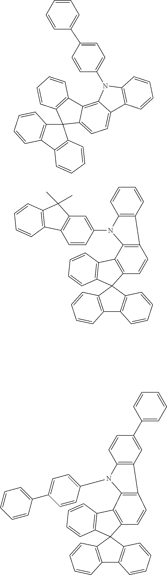


-
- 1) The compounds have improved sublimability compared to comparable compounds in which all three V1 to V3 groups are a group of the formula (3) or in which all three V1 to V3 groups are a —CR2—CR2— group.
- 2) The compounds have improved solubility compared to comparable compounds in which all three V1 to V3 groups are a group of the formula (3) or in which all three V1 to V3 groups are a —CR2—CR2— group.
- 3) The compounds, when used in an OLED, have improved efficiency compared to comparable compounds in which all three V1 to V3 groups are a group of the formula (3) or in which all three V1 to V3 groups are a CR2—CR2— group.
- 4) The compounds, when used in an OLED, have improved lifetime compared to comparable compounds in which all three V1 to V3 groups are a group of the formula (3) or in which all three V1 to V3 groups are a —CR2—CR2— group.

| Reactants | |||
| Ex. | Variant | Product | Yield |
| S2 |
 |
 |
83% |
| S3 |
 |
 |
85% |
| S4 |
 |
 |
88% |
| S5 |
 |
 |
74% |
 |
|||
| S6 |
 |
 |
70% |
| S7 |
 |
 |
65% |
 |
|||
| S8 |
 |
 |
69% |
 |
|||
| S9 |
 |
 |
67% |
 |
|||
| S10 |
 |
 |
65% |
 |
|||
| S11 |
 |
 |
70% |
 |
|||
| S12 |
 |
 |
73% |
| S13 |
 |
 |
77% |
| S14 |
 |
 |
77% |
| S15 |
 |
 |
77% |
| S16 |
 |
 |
73% |
| S17 |
 |
|
81% |
 |
|||

| Reactant | |||
| Ex. | Variant | Product | Yield |
| S51 | S2 A |
 |
90% |
| S52 | S3 A |
 |
89% |
| S53 | S4 A |
 |
87% |
| S54 | S5 A |
 |
90% |
| S55 | S6 A |
 |
87% |
| S56 | S7 A |
 |
84% |
| S57 | S8 A |
 |
88% |
| S58 | S9 B |
 |
85% |
| S59 | S10 A |
 |
87% |
| S60 | S11 A |
 |
90% |
| S61 | S12 A |
 |
94% |
| S62 | S13 A |
 |
91% |
| S63 | S14 A |
 |
90% |
| S64 | S15 A |
 |
90% |
| S65 | S16 A |
 |
90% |
| S66 |
 |
 |
55% |

| Ex. | Reactant | Product | Yield |
| S101 | S51 |
 |
90% |
| S102 | S52 |
 |
87% |
| S103 | S53 |
 |
91% |
| S104 | S54 |
 |
86% |
| S105 | S55 |
 |
93% |
| S106 | S56 |
 |
86% |
| S107 | S57 |
 |
86% |
| S108 | S58 |
 |
89% |
| S109 | S59 |
 |
87% |
| S110 | S60 |
 |
90% |
| S111 | S61 |
 |
88% |
| S112 | S62 |
 |
85% |
| S113 | S63 |
 |
83% |
| S114 | S64 |
 |
80% |
| S115 | S65 |
 |
76% |
| S116 |
 |
 |
80% |
| S117 |
 |
 |
89% |
| S118 |
 |
 |
86% |
| S119 |
 |
 |
85% |
| S120 |
 |
 |
77% |
| S121 |
 |
 |
80% |
| S122 | S66 |
 |
67% |
| S123 |
 |
 |
85% |
| S124 | S554 |
 |
76% |

| Ex. | Reactants | Product | Yield |
| S151 | S358 S101 |
 |
71% |
| S152 | S358 S102 |
 |
75% |
| S153 | S358 S103 |
 |
70% |
| S154 | S359 S101 |
 |
68% |
| S155 | S360 S103 |
 |
70% |
| S156 | S361 S100 |
 |
73% |
| S157 | S358 S104 |
 |
71% |
| S158 | S358 S105 |
 |
71% |
| S159 | S359 S105 |
 |
76% |
| S160 | S362 S106 |
 |
70% |
| S161 | S362 S107 |
 |
69% |
| S162 | S362 S108 |
 |
74% |
| S163 | S363 S106 |
 |
69% |
| S164 | S364 S106 |
 |
70% |
| S165 | S362 S109 |
 |
75% |
| S166 | S362 S110 |
 |
72% |
| S167 | S363 S109 |
 |
71% |
| S168 | S358 S111 |
 |
70% |
| S169 | S359 S112 |
 |
73% |
| S170 | S360 S113 |
 |
80% |
| S171 | S358 S114 |
 |
78% |
| S172 | S358 S115 |
 |
65% |
| S173 | S350 S100 |
 |
74% |
| S174 | S350 S104 |
 |
76% |
| S175 | S351 S100 |
 |
73% |
| S176 | S351 S105 |
 |
69% |
| S177 | S352 S105 |
 |
74% |
| S178 | S353 S104 |
 |
75% |
| S179 | S354 S104 |
 |
66% |
| S180 | S355 S101 |
 |
77% |
| S181 | S355 S104 |
 |
75% |
| S182 | S355 S110 |
 |
75% |
| S183 | S356 S104 |
 |
51% |
| S184 | S357 S104 |
 |
69% |

| Ex. | Reactants | Product | Yield |
| S201 | S151 |
 |
85% |
| S202 | S152 |
 |
90% |
| S203 | S153 |
 |
87% |
| S204 | S154 |
 |
86% |
| S205 | S155 |
 |
85% |
| S206 | S156 |
 |
90% |
| S207 | S157 |
 |
89% |
| S208 | S158 |
 |
90% |
| S209 | S159 |
 |
83% |
| S210 | S160 |
 |
81% |
| S211 | S161 |
 |
84% |
| S212 | S162 |
 |
85% |
| S213 | S163 |
 |
85% |
| S214 | S164 |
 |
82% |
| S215 | S165 |
 |
83% |
| S216 | S166 |
 |
85% |
| S217 | S167 |
 |
81% |
| S218 | S168 |
 |
84% |
| S219 | S169 |
 |
84% |
| S220 | S170 |
 |
90% |
| S221 | S171 |
 |
85% |
| S222 | S172 |
 |
86% |
| S223 | S173 |
 |
85% |
| S224 | S174 |
 |
80% |
| S225 | S175 |
 |
83% |
| S226 | S176 |
 |
81% |
| S227 | S177 |
 |
80% |
| S228 | S178 |
 |
85% |
| S229 | S179 |
 |
78% |
| S230 | S180 |
 |
80% |
| S231 | S181 |
 |
85% |
| S232 | S182 |
 |
84% |
| S233 | S183 |
 |
55% |
| S234 | S184 |
 |
83% |
| S235 | L211 |
 |
86% |

| Ex. | Reactant | Product | Yield |
| S251 | S201 |
 |
68% |
| S252 | S202 |
 |
65% |
| S253 | S203 |
 |
707% |
| S254 | S204 |
 |
71% |
| S255 | S205 |
 |
68% |
| S256 | S206 |
 |
67% |
| S257 | S207 |
 |
69% |
| S258 | S208 |
 |
70% |
| S259 | S209 |
 |
68% |
| S260 | S210 |
 |
70% |
| S261 | S211 |
 |
64% |
| S262 | S212 |
 |
66% |
| S263 | S213 |
 |
69% |
| S264 | S214 |
 |
67% |
| S265 | S215 |
 |
70% |
| S266 | S216 |
 |
70% |
| S267 | S217 |
 |
68% |
| S268 | S218 |
 |
65% |
| S269 | S219 |
 |
64% |
| S270 | S220 |
 |
69% |
| S271 | S221 |
 |
65% |
| S272 | S222 |
 |
70% |
| S273 | S223 |
 |
73% |
| S274 | S224 |
 |
69% |
| S275 | S225 |
 |
68% |
| S276 | S226 |
 |
72% |
| S277 | S227 |
 |
70% |
| S278 | S228 |
 |
65% |
| S279 | S229 |
 |
65% |
| S280 | S230 |
 |
68% |
| S281 | S231 |
 |
67% |
| S282 | S232 |
 |
90% |
| S283 | S233 |
 |
60% |
| S284 | S234 |
 |
63% |
| S285 | S235 |
 |
70% |

| Ex. | Reactant | Product | Yield |
| S301 | S401 |
 |
63% |
| S302 | S402 |
 |
66% |
| S303 | S403 |
 |
56% |
| S304 | S404 |
 |
59% |
| S305 | S405 |
 |
67% |
| S306 | S406 |
 |
27% |
| S307 | S407 |
 |
55% |
| S308 |
 |
 |
60% |
| S309 |
 |
 |
63% |
| S310 |
 |
 |
67% |
| S311 |
 |
 |
63% |
| S312 |
 |
 |
64% |
| S312- D8 |
 |
 |
70% |
| S313 |
 |
 |
51% |
| S313- D8 |
 |
 |
55% |
| S314 |
 |
 |
46% |
| S315 | S408 |
 |
28% |
| S315- D8 | S408 |
 |
32% |
| S316 | S409 |
 |
33% |
| S317 | S410 |
 |
35% |
| S318 | S411 |
 |
31% |
| S319 | S570 |
 |
35% |
| S319- D8 | S570 |
 |
30% |
| S320 | S571 |
 |
39% |
| S321 | S572 |
 |
30% |
| S322 |
 |
 |
68% |
| S323 |
 |
 |
66% |
| S324 |
 |
 |
70% |
| S324 |
 |
 |
67% |
| S325 |
 |
 |
66% |
| S326 |
 |
 |
60% |
| S327 |
|
 |
67% |

| Ex. | Reactant | Product | Yield |
| S351 | S301 |
 |
85% |
| S352 | S302 |
 |
88% |
| S353 | S303 |
 |
84% |
| S354 | S304 |
 |
76% |
| S355 | S305 |
 |
89% |
| S356 | S306 |
 |
65% |
| S357 | S307 |
 |
79% |
| S358 | S308 |
 |
87% |
| S359 | S309 |
 |
88% |
| S360 | S310 |
 |
85% |
| S361 | S311 |
 |
90% |
| S362 | S312 |
 |
86% |
| S362-D8 | S312 |
 |
84% |
| S363 | S313 |
 |
84% |
| S363-D8 | S313 |
 |
78% |
| S364 | S314 |
 |
89% |
| S365 | S315 |
 |
86% |
| S365-D8 | S315-D8 |
 |
81% |
| S366 | S316 |
 |
88% |
| S367 | S317 |
 |
83% |
| S368 | S318 |
 |
78% |
| S369 | S319 |
 |
75% |
| S369-D8 | S319-D8 |
 |
78% |
| S370 | S320 |
 |
71% |
| S371 | S321 |
 |
71% |
| S372 | S322 |
 |
75% |
| S373 | S323 |
 |
77% |
| S374 | S324 |
 |
73% |
| S374-D8 | S324-D8 |
 |
77% |
| S375 | S325 |
 |
68% |
| S376 | S326 |
 |
67% |
| S377 | S650 |
 |
55% |
| S378 | S651 |
 |
57% |
| S379 | S652 |
 |
61% |
| S379 | S653 |
 |
66% |
| S380 | S327 |
 |
68% |

| S401 |
 |
 |
56% |
| 1394374-23-2 | |||
| S402 |
 |
 |
62% |
| 1621467-82-0 | |||
| S403 |
 |
 |
66% |
| 1466412-09-8 | |||
| S404 |
 |
 |
60% |
| 1989597-13-8 | |||
| S405 |
 |
|
49% |
| 1312478-63-9 | |||
| S406 | S66 |
 |
31% |
| Recrystallization of the crude product | |||
| from acetonitrile/MeOH | |||
| S407 |
 |
 |
57% |
| 1989597-91-2 | |||
| S408 | S550 |
 |
53% |
| S409 | S551 |
 |
50% |
| S410 | S552 |
 |
56% |
| S411 | S553 |
 |
48% |

| Ex. | Reactant | Product | Yield |
| S451 |
 |
 |
68% |
| [504413-43-8] | |||
| S452 |
 |
 |
74% |
| [73402-91-2] | |||
| S453 |
 |
 |
77% |
| [1852499-57-0] | |||
| S454 |
 |
 |
75% |
| [89009-22-3] | |||
| S455 |
|
 |
80% |
| [27012-25-5] | |||
| S456 |
 |
 |
78% |
| [875462-73-0] | |||
| S457 |
 |
 |
74% |
| [1415352-89-8] | |||
| S458 |
 |
 |
75% |
| [1989596-02-2] | |||
| S459 |
 |
 |
63% |
| [1989596-06-6] | |||
| S460 | S10 |
 |
64% |

| Ex. | Reactant | Product | Yield |
| S501 | S451 |
 |
78% |
| S502 | S452 |
 |
75% |
| S503 | S453 |
 |
76% |
| S504 | S454 |
 |
70% |
| S505 | S455 |
 |
80% |
| S506 | S456 |
 |
81% |
| S507 | S457 |
 |
79% |
| S508 | S458 |
 |
77% |
| S509 | S459 |
 |
74% |
| S510 | S460 |
 |
75% |

| Ex. | Reactant | Product | Yield |
| S551 |
 |
 |
72% |
| 1493784-12-5 | |||
| S552 |
 |
 |
68% |
| 1493784-11-4 | |||
| S553 |
 |
 |
70% |
| 327096-10-6 | |||
| S554 |
|
 |
36% |
| 512171-81-2 | Purification via flash chromatography | ||

A)


| Ex. | Reactant | Product | Yield |
| S571 |
 |
 |
65% |
| 1072952-45-4 | |||
| S572 |
 |
 |
61% |
| 906744-85-2 | |||

A)


| Reactant | |||
| Ex. | Variant 1 | Product | Yield |
| S601 |
 |
 |
53% |
| 1080632-76-3 | |||
| S602 |
 |
 |
48% |
| 1383628-42-9 | |||
| S603 |
 |
 |
46% |
| 2173324-06-4 | |||
| S604 |
 |
 |
49% |
| 1191061-81-0 | |||
| S605 |
 |
 |
30% 58% |
| Variant 1 | |||
| Variant 2 | |||
| 654664-63-8 | |||
| S606 |
 |
 |
47% |
| 395087-89-5 | |||
| S607 |
 |
 |
48% |
| S607 |
 |
 |
55% |
| 854952-58-2 | |||
| S608 |
 |
 |
39% 60% |
| Variant 1 | |||
| Variant 2 | |||
| 419536-33-7 | |||
| S609 |
 |
 |
53% |
| * over three stages | |||

| Ex. | Reactants | Product | Yield |
| S651 |
|
 |
38% |
| 2096371-94-5 | |||
| 85391-13-5 | |||
| S652 |
 |
 |
27% |
| 2096371-94-5 | |||
| 1689568-10-2 | |||
| S653 |
|
 |
24% |
| 2096371-94-5 | |||
| S17 | |||

| Ex. | Reactant | Product | Yield |
| L2 |
 |
 |
78% |
| S250 | |||
| 1080632-76-3 | |||
| L3 |
 |
 |
78% |
| S250 | |||
| 912844-88-3 | |||
| L4 |
 |
 |
74% |
| S250 | |||
| 1401577-23-8 | |||
| L5 |
 |
 |
73% |
| S250 | |||
| 1115023-84-1 | |||
| L6 |
 |
 |
77% |
| S250 | |||
| 1056113-50-8 | |||
| L7 |
 |
 |
75% |
| S250 | |||
| 1362691-15-3 | |||
| L8 |
 |
 |
81% |
| S251 | |||
| 144432-80-4 | |||
| L9 |
 |
 |
77% |
| S252 | |||
| 144432-80-4 | |||
| L10 |
 |
 |
79% |
| S253 | |||
| 197770-80-1 | |||
| L11 |
 |
 |
74% |
| S254 | |||
| 144432-80-4 | |||
| L12 |
 |
 |
82% |
| S255 | |||
| 569343-09-5 | |||
| L13 |
 |
 |
78% |
| S256 | |||
| 2007912-69-6 | |||
| L14 |
 |
 |
79% |
| S257 | |||
| 144432-80-4 | |||
| L15 |
 |
 |
76% |
| S257 | |||
| 912844-88-3 | |||
| L16 |
 |
 |
80% |
| S257 | |||
| 1056113-50-8 | |||
| L17 |
 |
 |
73% |
| S258 | |||
| 1197180-12-3 | |||
| L18 |
 |
 |
74% |
| S259 | |||
| 1383628-42-9 | |||
| L19 |
 |
 |
78% |
| S260 | |||
| 144432-80-4 | |||
| L20 |
 |
 |
80% |
| S261 | |||
| 144432-80-4 | |||
| L21 |
 |
 |
73% |
| S261 | |||
| 1056113-50-8 | |||
| L22 |
 |
 |
70% |
| S262 | |||
| 144432-80-4 | |||
| L23 |
 |
 |
76% |
| S263 | |||
| 144432-80-4 | |||
| L24 |
 |
 |
72% |
| S264 | |||
| 1959608-16-2 | |||
| L25 |
 |
 |
80% |
| S265 | |||
| 144432-80-4 | |||
| L26 |
 |
 |
74% |
| S265 | |||
| 912844-88-3 | |||
| L27 |
 |
 |
78% |
| S266 | |||
| 144432-80-4 | |||
| L28 |
 |
 |
74% |
| S267 | |||
| 144432-80-4 | |||
| L29 |
 |
 |
76% |
| S267 | |||
| 583823-92-1 | |||
| L30 |
 |
 |
72% |
| S268 | |||
| 144432-80-4 | |||
| L31 |
 |
 |
74% |
| S269 | |||
| 1362691-15-3 | |||
| L32 |
 |
 |
78% |
| S270 | |||
| 912844-88-3 | |||
| L33 |
 |
 |
75% |
| S271 | |||
| 144432-80-4 | |||
| L34 |
 |
 |
80% |
| S272 | |||
| 144432-80-4 | |||
| L35 |
 |
 |
76% |
| S273 | |||
| 144432-80-4 | |||
| L36 |
 |
 |
79% |
| S274 | |||
| 144432-80-4 | |||
| L37 |
 |
 |
80% |
| S275 | |||
| 1362691-15-3 | |||
| L38 |
 |
 |
73% |
| S276 | |||
| 1056113-50-8 | |||
| L39 |
 |
 |
79% |
| S277 | |||
| 144432-80-4 | |||
| L40 |
 |
 |
71% |
| S278 | |||
| 144432-80-4 | |||
| L41 |
 |
 |
75% |
| S279 | |||
| 144432-80-4 | |||
| L42 |
 |
 |
77% |
| S280 | |||
| 1056113-50-8 | |||
| L43 |
 |
 |
79% |
| S281 | |||
| 144432-80-4 | |||
| L44 |
 |
 |
80% |
| S282 | |||
| 144432-80-4 | |||
| L45 |
 |
 |
55% |
| S283 | |||
| 1383628-42-9 | |||
| L46 |
 |
 |
77% |
| S284 | |||
| 144432-80-4 | |||
| L47 |
 |
 |
78% |
| S285 | |||
| 144432-80-4 | |||

| Ex. | Reactants | Product | Yield |
| L101 | S358  |
 |
75% |
| L102 | S359  |
 |
70% |
| L103 | S360  |
 |
72% |
| L104 | S361  |
 |
75% |
| L105 | S359  |
 |
68% |
| L106 | S362  |
 |
74% |
| L107 | S362  |
 |
80% |
| L108 | S362  |
 |
78% |
| L109 | S362  |
 |
81% |
| L109-D8 | S362-08  |
 |
79% |
| L110 | S363  |
 |
79% |
| L111 | S363  |
 |
72% |
| L112 | S363  |
 |
75% |
| L113-D8 | S363-08 S600 |
 |
70% |
| L114 | S362 S601 |
 |
71% |
| L115 | S362 S602 |
 |
63% |
| L116 | S362 S603 |
 |
59% |
| L117 | S363 S604 |
 |
65% |
| L118 | S363 S605 |
 |
78% |
| L119 | S362 S606 |
 |
74% |
| L120 | S363 S607 |
 |
70% |
| L121 | S362 S608 |
 |
77% |
| L122 | S363 S609 |
 |
68% |
| L123 | S362 S610 |
 |
65% |
| L124 | S365 S600 |
 |
66% |
| L124-D8 | S365-D8 S600 |
 |
67% |
| L125 | S366 S609 |
 |
61% |
| L126 | S367 S605 |
 |
69% |
| L127 | S368 S601 |
 |
63% |
| L128 | S369 S609 |
 |
60% |
| L128-D8 | S369-08 S609 |
 |
68% |
| L129 | S370 S601 |
 |
66% |
| L130 | S371 S605 |
 |
63% |
| L131 | S372 S600 |
 |
65% |
| L132 | S373 S601 |
 |
67% |
| L133 | S374 S609 |
 |
64% |
| L133-D8 | S374-D8 S609 |
 |
67% |
| L134 | S375 S606 |
 |
60% |
| L135 | S376 S601 |
 |
64% |
| L136 | S374 S600 |
 |
67% |
| L136-D8 | S374-08 S600 |
 |
65% |
| L137-D8 | S374-08 S601 |
 |
68% |
| L138-D8 | S374-08 S605 |
 |
65% |
| L139-D8 | S374-08 S606 |
 |
63% |
| L140 | S650  |
 |
60% |
| L141 | S651 S600 |
 |
67% |
| L142 | S651 S609 |
 |
64% |
| L143 | S652 S605 |
 |
66% |
| L144 | S652 S606 |
 |
63% |
| L145 | S359 S600 |
 |
67% |
| L146 | S359 S605 |
 |
70% |
| L147 | S359 S606 |
 |
68% |
| L148 | S359 S601 |
 |
65% |
| L149 | S379 S124 |
 |
67% |
| L150 | S380 S600 |  |
48% |
| L151 | S380 S601 |  |
53% |
| L152 | S380 S605 |  |
57% |
| L153 | S362  |
 |
63% |
| L153-D8 | S362-D8 1989597-42-3 |
 |
60% |
| L154 | S363 1989597-42-3 |
 |
65% |
| L154-D8 | S363-D8 1989597-42-3 |
 |
62% |
| L155-D8 | S365-D8 1989597-42-3 |
 |
70% |
| L156 | S371 1989597-42-3 |
 |
71% |
| L157-D8 | S374-D8 1989597-42-3 |
 |
68% |
| L158 | S380 1989597-42-3 |  |
70% |

| Ex. | Reactants | Product | Yield |
| L201 | S501  |
 |
70% |
| L202 | S501  |
 |
56% |
| L203 | S502  |
 |
74% |
| L204 | S503  |
 |
73% |
| L205 | S504  |
 |
58% |
| L206 | S505  |
 |
69% |
| L207 | S505  |
 |
70% |
| L208 | S507  |
 |
68% |
| L209 | S508  |
 |
72% |
| L210 | S509  |
 |
70% |
| L211 | S510  |
 |
67% |

| Ex. | Ligand | Product Variant A/extractant* | Yield |
| Ir(L2) | L2 |
 |
67% |
| Ir(L3) | L3 |
 |
63% |
| Ir(L4) | L4 |  |
60% |
| Ir(L5) | L5 |
 |
55% |
| Ir(L6) | L6 |
 |
61% |
| Ir(L7) | L7 |
 |
59% |
| Ir(L8) | L8 |
 |
61% |
| Ir(L9) | L9 |
 |
57% |
| Ir(L10) | L10 |
 |
62% |
| Ir(L11) | L11 |
 |
62% |
| Ir(L12) | L12 |
 |
64% |
| Ir(L13) | L13 |
 |
60% |
| Ir(L14) | L14 |
 |
58% |
| Ir(L15) | L15 |
 |
60% |
| Ir(L16) | L16 |
 |
64% |
| Ir(L17) | L17 |
 |
57% |
| Ir(L18) | L18 |
 |
59% |
| Ir(L19) | L19 |
 |
66% |
| Ir(L20) | L20 |
 |
62% |
| Ir(L21) | L21 |
 |
60% |
| Ir(L22) | L22 |
 |
57% |
| Ir(L23) | L23 |
 |
60% |
| Ir(L24) | L24 |
 |
57% |
| Ir(L25) | L25 |
 |
64% |
| Ir(L26) | L26 |
 |
63% |
| Ir(L27) | L27 |
 |
59% |
| Ir(L28) | L28 |
 |
58% |
| Ir(L29) | L29 |
 |
62% |
| Ir(L30) | L30 |
 |
58% |
| Ir(L31) | L31 |  |
60% |
| Ir(L32) | L32 |
 |
60% |
| Ir(L33) | L33 |
 |
63% |
| Ir(L34) | L34 |
 |
60% |
| Ir(L35) | L35 |
 |
61% |
| Ir(L36) | L36 |
 |
57% |
| Ir(L37) | L37 |
 |
55% |
| Ir(L38) | L38 |
 |
58% |
| Ir(L39) | L39 |
 |
56% |
| Ir(L40) | L40 |
 |
60% |
| Ir(L41) | L41 |
 |
53% |
| Ir(L42) | L42 |
 |
60% |
| Ir(L43) | L43 |
 |
63% |
| Ir(L44) | L44 |
 |
62% |
| Ir(L45) | L45 |  |
40% |
| Ir(L46) | L46 |  |
55% |
| Ir(L47) | L47 |
 |
61% |
| Ir(L100) | L100 |
 |
65% |
| Ir(L101) | L101 |
 |
67% |
| Ir(L102) | L102 |
 |
63% |
| Ir(L103) | L103 |
 |
65% |
| Ir(L104) | L104 |
 |
58% |
| Ir(L105) | L105 |
 |
61% |
| Ir(L106) | L106 |
 |
64% |
| Ir(L107) | L107 |
 |
67% |
| Ir(L108) | L108 |
 |
65% |
| Ir(L109) | L109 |
 |
67% |
| Ir(L109-D8) | L109-D8 |
 |
65% |
| Ir(L110) | L110 |
 |
63% |
| Ir(L111) | L111 |
 |
61% |
| Ir(L112) | L112 |
 |
64% |
| Ir(L113-D8) | L113-D8 |
 |
66% |
| Ir(L114) | L114 |
 |
63% |
| Ir(L115) | L115 |
 |
60% |
| Ir(L116) | L116 |
 |
51% |
| Ir(L117) | L117 |
 |
59% |
| Ir(L118) | L118 |
 |
67% |
| Ir(L119) | L119 |
 |
65% |
| Ir(L120) | L120 |
 |
63% |
| Ir(L121) | L121 |
 |
69% |
| Ir(L122) | L122 |
 |
65% |
| Ir(L123) | L123 |
 |
67% |
| Ir(L124) | L124 |
 |
55% |
| Ir(L124-D8) | L124-D8 |
 |
52% |
| Ir(L125) | L125 |
 |
43% |
| Ir(L126) | L126 |
 |
47% |
| Ir(L127) | L127 |
 |
50% |
| Ir(L128) | L128 |
 |
48% |
| Ir(L128-D8) | L128-D8 |
 |
52% |
| Ir(L129) | L129 |
 |
37% |
| Ir(L130) | L130 |
 |
39% |
| Ir(L131) | L131 |
 |
70% |
| Ir(L132) | L132 |
 |
68% |
| Ir(L133) | L133 |
 |
67% |
| Ir(L133-D8) | L133-D8 |
 |
69% |
| Ir(L134) | L134 |
 |
56% |
| Ir(L135) | L135 |
 |
61% |
| Ir(L136) | L136 |
 |
63% |
| Ir(L136-D8) | L136-D8 |
 |
66% |
| Ir(L137-D8) | L137-D8 |
 |
72% |
| Ir(L138-D8) | L138-D8 |
 |
69% |
| Ir(L139-D8) | L139-D8 |
 |
65% |
| Ir(L140) | L140 |
 |
43% |
| Ir(L141) | L141 |
 |
67% |
| Ir(L142) | L142 |
 |
64% |
| Ir(L143) | L143 |
 |
54% |
| Ir(L144) | L144 |
 |
57% |
| Ir(L145) | L145 |
 |
62% |
| Ir(L146) | L146 |
 |
65% |
| Ir(L147) | L147 |
 |
60% |
| Ir(L148) | L148 |
 |
63% |
| Ir(L149) | L149 |
 |
56% |
| Ir(L150) | L150 |
 |
45% |
| Ir(L151) | L151 |
 |
47% |
| Ir(L152) | L152 |
 |
51% |
| Ir(L153) | L153 |
 |
60% |
| Ir(L153-D8) | L153-D8 |
 |
58% |
| Ir(L154) | L154 |
 |
61% |
| Ir(L154-D8) | L154-D8 |
 |
63% |
| Ir(L155-D8) | L155-D8 |
 |
57% |
| Ir(L156) | L156 |
 |
60% |
| Ir(L157-D8) | L157-D8 |
 |
64% |
| Ir(L158) | L158 |
 |
48% |
| Ir(L200) | L200 |
 |
66% |
| Ir(L201) | L201 |
 |
63% |
| Ir(L202) | L202 |
 |
58% |
| Ir(L203) | L203 |
 |
63% |
| Ir(L204) | L204 |
 |
54% |
| Ir(L205) | L205 |
 |
56% |
| Ir(L206) | L206 |
 |
68% |
| Ir(L207) | L207 |
 |
65% |
| Ir(L208) | L208 |
 |
67% |
| Ir(L209) | L209 |
 |
61% |
| Ir(L210) | L210 |
 |
65% |
| *if different | |||
| Ex. | Reactant | Product | Yield |
| Ir(L10-D3) | Ir(L10) |
 |
90% |
| Ir(L11-D9) | Ir(L11) |
 |
89% |
| Ir(L23-D10) | Ir(L23) |
 |
88% |
| Ir(L28-D10) | Ir(L28) |
 |
91% |
| Ir(L153-D11) | Ir(L153-D8) |
 |
93% |
| Ir(L154-D17) | Ir(L154-D8) |
 |
89% |
| Ex. | Reactant | Product | Yield |
| Ir(L1-D17) | Ir(L1) |  | 90% |
2) Bromination of the Metal Complexes

| Reactant | ||
| Ex. | Bromination product | Yield |
| Ir(L6-2Br) | Ir(L6) | 94% |
 |
||
| Ir(L8-2Br) | Ir(L8) | 93% |
 |
||
| Ir(L14-3Br) | Ir(L14) | 94% |
 |
||
| Ir(L19-2Br) | Ir(L19) | 90% |
 |
||
| Ir(L28-3Br) | Ir(L28) | 90% |
 |
||
| Ir(L100-3Br) | Ir(L100) | 93% |
 |
||
| Ir(L200-3Br) | Ir(L200) | 90% |
 |
||
| Ir(L123-2Br) | Ir(L123) | 93% |
 |
||
| Ir(L124-3Br) | Ir(L124) | 90% |
 |
||
| Ir(L136-D8-Br) | Ir(L136-D8) | 75% |
| 1 eq NBS | ||
 |
||

| Reactant | ||
| Ex. | Cyanation product | Yield |
| Ir(L6-2CN) | Ir(L6-2Br) | 57% |
 |
||
| Ir(L200-3CN) | Ir(L200-3Br) | 58% |
 |
||
| Ir(L123-2CN) |
 |
53% |
| Ir(L124-3CN) |
 |
41% |
| Ir(L136-D8-CN) |
 |
61% |

| Bromide/boronic acid/variant | ||
| Ex. | Product | Yield |
| Ir2 | Ir(L8-2Br) / [5122-95-2] / A | 70% |
 |
||
| Ir3 | Ir(L14-3Br) / 1313018-07-3 / B, DMSO, K3PO4 × H20, | 62% |
| Pd(ac)2:Triphenyphosphine 1:3 | ||
 |
||
| Ir4 | Ir(L19-2Br) / [854952-58-2] / A | 74% |
 |
||
| Ir5 | Ir(L28-3Br) / [100124-06-9] / A | 56% |
 |
||
| Ir6 | Ir(L100-3Br) / [5122-95-2] / A | 68% |
 |
||
| Ir7 | Ir(L200-3Br) / [1703019-86-6] / A | 60% |
 |
||
| Example | CAS | ||
| 1 | 1448677-51-7 | ||
| 2 | 1899022-50-4 | ||
| 3 | 1448677-51-7 | ||
| 4 | 881913-00-4 | ||
| 5 | 2247552-50-5 | ||
| 6 | 491880-61-6 | ||
| 7 | 1643142-51-1 | ||
| 8 | 1443276-75-2 | ||
| 9 | 1056044-55-3 | ||
| 10 | 1622168-79-9 | ||
| 11 | 1308841-85-1 | ||
| 12 | 2182638-63-5 | ||
| 13 | 2159145-70-5 | ||
| 14 | 2101985-67-3 | ||
| 15 | 400607-34-3 | ||
| 16 | 2007912-79-8 | ||
| 17 | 1356465-28-5 | ||
| 18 | 1788946-55-3 | ||
| 19 | 2226968-34-7 | ||
| 20 | 1646636-93-2 | ||
5) Ullmann Coupling with the Brominated Iridium Complexes

| Reactants | ||
| Ex. | Product | Yield |
| Ir51 | Ir(L8-2Br) / [103012-26-6] | 67% |
 |
||
| Ir52 | Ir(L14-3Br) / [1257220-47-5] | 61% |
 |
||
| Ir53 | Ir(L28-3Br) / [88590-005] | 66% |
 |
||
| Ir54 | Ir(L200-3Br) / [244-69-9] | 60% |
 |
||


B) Introduction During the Ligand Synthesis


| TABLE 1 |
| Structure of the OLEDs |
| HTL2 | EML | HBL | ETL | |
| Ex. | thickness | thickness | thickness | thickness |
| Ref.D1 | HTM2 | M1:M2:Ir-Ref.1 | ETM1 | ETM1:ETM2 |
| 10 nm | (55%:30%:15%) | 10 nm | (50%:50%) | |
| 30 nm | 30 nm | |||
| Ref.D2 | HTM2 | M1:M2:Ir-Ref.2 | ETM1 | ETM1:ETM2 |
| 10 nm | (55%:30%:15%) | 10 nm | (50%:50%) | |
| 30 nm | 30 nm | |||
| Ref.D3 | HTM2 | M1:M2:Ir-Ref.3 | ETM1 | ETM1:ETM2 |
| 10 nm | (55%:30%:15%) | 10 nm | (50%:50%) | |
| 30 nm | 30 nm | |||
| Ref.D4 | HTM2 | M1:M2:Ir-Ref.4 | ETM1 | ETM1:ETM2 |
| 10 nm | (55%:30%:15%) | 10 nm | (50%:50%) | |
| 30 nm | 30 nm | |||
| D1 | HTM2 | M1:M2:Ir(L100) | ETM1 | ETM1:ETM2 |
| 10 nm | (55%:30%:15%) | 10 nm | (50%:50%) | |
| 30 nm | 30 nm | |||
| D2 | HTM2 | M1:M2:Ir(L107) | ETM1 | ETM1:ETM2 |
| 10 nm | (55%:30%:15%) | 10 nm | (50%:50%) | |
| 30 nm | 30 nm | |||
| D3 | HTM2 | M1:M2:Ir(L200) | ETM1 | ETM1:ETM2 |
| 10 nm | (55%:30%:15%) | 10 nm | (50%:50%) | |
| 30 nm | 30 nm | |||
| D4 | HTM2 | M1:M2:Ir(L207) | ETM1 | ETM1:ETM2 |
| 10 nm | (55%:30%:15%) | 10 nm | (50%:50%) | |
| 30 nm | 30 nm | |||
| D5A | HTM2 | M1:M2:Ir(L1) | ETM1 | ETM1:ETM2 |
| 10 nm | (55%:30%:15%) | 10 nm | (50%:50%) | |
| 30 nm | 30 nm | |||
| D5B | HTM2 | M1:M7:Ir(L1) | ETM1 | ETM1:ETM2 |
| 10 nm | (49%:29%:22%) | 10 nm | (50%:50%) | |
| 30 nm | 30 nm | |||
| D5C | HTM2 | M1:M8:Ir(L1) | ETM1 | ETM1:ETM2 |
| 10 nm | (68%:25%:7%) | 10 nm | (50%:50%) | |
| 30 nm | 30 nm | |||
| D5D | HTM2 | M1:M9:Ir(L1) | ETM1 | ETM1:ETM2 |
| 10 nm | (58%:35%:7%) | 10 nm | (50%:50%) | |
| 30 nm | 30 nm | |||
| D5E | HTM2 | M1:M9:Ir(L1) | ETM1 | ETM1:ETM2 |
| 10 nm | (46%:50%:4%) | 10 nm | (50%:50%) | |
| 30 nm | 30 nm | |||
| D6A | HTM2 | M1:M2:Ir(L14) | ETM1 | ETM1:ETM2 |
| 10 nm | (62%:31%:7%) | 10 nm | (50%:50%) | |
| 30 nm | 30 nm | |||
| D6B | HTM2 | M1:M2:Ir(L14) | ETM1 | ETM1:ETM2 |
| 10 nm | (59%:29%:12%) | 10 nm | (50%:50%) | |
| 30 nm | 30 nm | |||
| D6C | HTM2 | M1:M2:Ir(L14) | ETM1 | ETM1:ETM2 |
| 10 nm | (56%:27%:17%) | 10 nm | (50%:50%) | |
| 30 nm | 30 nm | |||
| D6D | HTM2 | M1:M2:Ir(L14) | ETM1 | ETM1:ETM2 |
| 10 nm | (41.5%:41.5%:17%) | 10 nm | (50%:50%) | |
| 30 nm | 30 nm | |||
| D6E | HTM2 | M1:M7:Ir(L14) | ETM1 | ETM1:ETM2 |
| 10 nm | (26%:52%:22%) | 10 nm | (50%:50%) | |
| 30 nm | 30 nm | |||
| D6F | HTM2 | M1:M11:Ir(L14) | ETM1 | ETM1:ETM2 |
| (26%:52%:22%) | 10 nm | (50%:50%) | ||
| 30 nm | 30 nm | |||
| D7 | HTM2 | M6:Ir(L30) | ETM1 | ETM1:ETM2 |
| 10 nm | (88%:12%) | 10 nm | (50%:50%) | |
| 40 nm | 30 nm | |||
| D8A | HTM3 | M1:M11:Ir(L43) | ETM1 | ETM1:ETM2 |
| 10 nm | (26%:52%:22%) | 10 nm | (50%:50%) | |
| 30 nm | 30 nm | |||
| D8B | HTM3 | M1:M2:Ir(L43) | ETM1 | ETM1:ETM2 |
| 10 nm | (47%:47%:6%) | 10 nm | (50%:50%) | |
| 30 nm | 30 nm | |||
| D9 | HTM3 | M1:M11:Ir(L25) | ETM1 | ETM1:ETM2 |
| 10 nm | (55%:27%:18%) | 10 nm | (50%:50%) | |
| 30 nm | 30 nm | |||
| D10 | HTM3 | M1:Ir(L136) | ETM1 | ETM1:ETM2 |
| 10 nm | (80%:20%) | 10 nm | (50%:50%) | |
| 30 nm | 30 nm | |||
| D11 | HTM3 | M1:M2:Ir(L136) | ETM1 | ETM1:ETM2 |
| 10 nm | (68%:20%:12%) | 10 nm | (50%:50%) | |
| 30 nm | 30 nm | |||
| D12 | HTM3 | M1:Ir(L136-D8) | ETM1 | ETM1:ETM2 |
| 10 nm | (80%:20%) | 10 nm | (50%:50%) | |
| 30 nm | 30 nm | |||
| D13 | HTM3 | M1:M7:Ir(L2) | ETM1 | ETM1:ETM2 |
| 10 nm | (57%:28%:15%) | 10 nm | (50%:50%) | |
| 30 nm | 30 nm | |||
| D14 | HTM3 | M1:M7:Ir(L3) | ETM1 | ETM1:ETM2 |
| 10 nm | (57%:28%:15%) | 10 nm | (50%:50%) | |
| 30 nm | 30 nm | |||
| D15 | HTM3 | M1:M7:Ir(L6) | ETM1 | ETM1:ETM2 |
| 10 nm | (57%:28%:15%) | 10 nm | (50%:50%) | |
| 30 nm | 30 nm | |||
| D16 | HTM3 | M1:M7:Ir(L7) | ETM1 | ETM1:ETM2 |
| 10 nm | (57%:28%:15%) | 10 nm | (50%:50%) | |
| 30 nm | 30 nm | |||
| D17 | HTM3 | M1:M7:Ir(L8) | ETM1 | ETM1:ETM2 |
| 10 nm | (57%:28%:15%) | 10 nm | (50%:50%) | |
| 30 nm | 30 nm | |||
| D18 | HTM3 | M1:M7:Ir(L9) | ETM1 | ETM1:ETM2 |
| 10 nm | (57%:28%:15%) | 10 nm | (50%:50%) | |
| 30 nm | 30 nm | |||
| D19 | HTM3 | M1:M7:Ir(L11) | ETM1 | ETM1:ETM2 |
| 10 nm | (57%:28%:15%) | 10 nm | (50%:50%) | |
| 30 nm | 30 nm | |||
| D20 | HTM3 | M1:M11:Ir(L15) | ETM1 | ETM1:ETM2 |
| 10 nm | (26%:52%:22%) | 10 nm | (50%:50%) | |
| 30 nm | 30 nm | |||
| D21 | HTM3 | M1:M11:Ir(L16) | ETM1 | ETM1:ETM2 |
| 10 nm | (26%:52%:22%) | 10 nm | (50%:50%) | |
| 30 nm | 30 nm | |||
| D22 | HTM3 | M1:M11:Ir(L17) | ETM1 | ETM1:ETM2 |
| 10 nm | (26%:52%:22%) | 10 nm | (50%:50%) | |
| 30 nm | 30 nm | |||
| D23 | HTM3 | M1:M2:Ir(L23) | ETM1 | ETM1:ETM2 |
| 10 nm | (62%:31%:7%) | 10 nm | (50%:50%) | |
| 30 nm | 30 nm | |||
| D24 | HTM3 | M1:M11:Ir(L26) | ETM1 | ETM1:ETM2 |
| 10 nm | (55%:27%:18%) | 10 nm | (50%:50%) | |
| 30 nm | 30 nm | |||
| D25 | HTM3 | M1:M11:Ir(L27) | ETM1 | ETM1:ETM2 |
| 10 nm | (55%:27%:18%) | 10 nm | (50%:50%) | |
| 30 nm | 30 nm | |||
| D26 | HTM3 | M1:M11:Ir(L28) | ETM1 | ETM1:ETM2 |
| 10 nm | (55%:27%:18%) | 10 nm | (50%:50%) | |
| 30 nm | 30 nm | |||
| D27 | HTM3 | M1:M11:Ir(L29) | ETM1 | ETM1:ETM2 |
| 10 nm | (55%:27%:18%) | 10 nm | (50%:50%) | |
| 30 nm | 30 nm | |||
| D28 | HTM2 | M6:Ir(L31) | ETM1 | ETM1:ETM2 |
| 10 nm | (95%:5%) | 10 nm | (50%:50%) | |
| 40 nm | 30 nm | |||
| D29 | HTM3 | M1:M2:Ir(L44) | ETM1 | ETM1:ETM2 |
| 10 nm | (47%:47%:6%) | 10 nm | (50%:50%) | |
| 30 nm | 30 nm | |||
| D30 | HTM3 | M1:M2:Ir(L42) | ETM1 | ETM1:ETM2 |
| 10 nm | (47%:47%:6%) | 10 nm | (50%:50%) | |
| 30 nm | 30 nm | |||
| D31 | HTM3 | M1:M11:Ir(L113) | ETM1 | ETM1:ETM2 |
| 10 nm | (55%:27%:18%) | 10 nm | (50%:50%) | |
| 30 nm | 30 nm | |||
| D32 | HTM3 | M1:M11:Ir(L114) | ETM1 | ETM1:ETM2 |
| 10 nm | (55%:27%:18%) | 10 nm | (50%:50%) | |
| 30 nm | 30 nm | |||
| D33 | HTM3 | M1:M11:Ir(L115) | ETM1 | ETM1:ETM2 |
| 10 nm | (55%:27%:18%) | 10 nm | (50%:50%) | |
| 30 nm | 30 nm | |||
| D34 | HTM3 | M1:M11:Ir(L118) | ETM1 | ETM1:ETM2 |
| 10 nm | (55%:27%:18%) | 10 nm | (50%:50%) | |
| 30 nm | 30 nm | |||
| D35 | HTM3 | M1:M11:Ir(L119) | ETM1 | ETM1:ETM2 |
| 10 nm | (50%:30%:20%) | 10 nm | (50%:50%) | |
| 30 nm | 30 nm | |||
| D36 | HTM3 | M1:M11:Ir(L120) | ETM1 | ETM1:ETM2 |
| 10 nm | (50%:30%:20%) | 10 nm | (50%:50%) | |
| 30 nm | 30 nm | |||
| D37 | HTM3 | M1:M11:Ir(L122) | ETM1 | ETM1:ETM2 |
| 10 nm | (55%:27%:18%) | 10 nm | (50%:50%) | |
| 30 nm | 30 nm | |||
| D38 | HTM3 | M1:M11:Ir(L123) | ETM1 | ETM1:ETM2 |
| 10 nm | (55%:27%:18%) | 10 nm | (50%:50%) | |
| 30 nm | 30 nm | |||
| D39 | HTM3 | M1:M2:Ir(L124) | ETM1 | ETM1:ETM2 |
| 10 nm | (68%:20%:12%) | 10 nm | (50%:50%) | |
| 30 nm | 30 nm | |||
| D40 | HTM3 | M1:M2:Ir(L124-D8) | ETM1 | ETM1:ETM2 |
| 10 nm | (68%:20%:12%) | 10 nm | (50%:50%) | |
| 30 nm | 30 nm | |||
| D41 | HTM3 | M1:M9:Ir(L128) | ETM1 | ETM1:ETM2 |
| 10 nm | (68%:20%:12%) | 10 nm | (50%:50%) | |
| 30 nm | 30 nm | |||
| D42 | HTM3 | M1:M2:Ir(L131) | ETM1 | ETM1:ETM2 |
| 10 nm | (62%:31%:7%) | 10 nm | (50%:50%) | |
| 30 nm | 30 nm | |||
| D43 | HTM3 | M1:M2:Ir(L132) | ETM1 | ETM1:ETM2 |
| 10 nm | (62%:31%:7%) | 10 nm | (50%:50%) | |
| 30 nm | 30 nm | |||
| D44 | HTM3 | M1:M2:Ir(L133) | ETM1 | ETM1:ETM2 |
| 10 nm | (62%:31%:7%) | 10 nm | (50%:50%) | |
| 30 nm | 30 nm | |||
| D45 | HTM3 | M1:M2:Ir(L133-D8) | ETM1 | ETM1:ETM2 |
| 10 nm | (62%:31%:7%) | 10 nm | (50%:50%) | |
| 30 nm | 30 nm | |||
| D46 | HTM3 | M1:M2:Ir(L137) | ETM1 | ETM1:ETM2 |
| 10 nm | (62%:31%:7%) | 10 nm | (50%:50%) | |
| 30 nm | 30 nm | |||
| D47 | HTM3 | M1:M2:Ir(L138) | ETM1 | ETM1:ETM2 |
| 10 nm | (62%:31%:7%) | 10 nm | (50%:50%) | |
| 30 nm | 30 nm | |||
| D48 | HTM3 | M1:M2:Ir(L139) | ETM1 | ETM1:ETM2 |
| 10 nm | (62%:31%:7%) | 10 nm | (50%:50%) | |
| 30 nm | 30 nm | |||
| D49 | HTM3 | M1:M11:Ir(L28-D10) | ETM1 | ETM1:ETM2 |
| 10 nm | (55%:27%:18%) | 10 nm | (50%:50%) | |
| 30 nm | 30 nm | |||
| D50 | HTM3 | M1:M2:Ir(L123-2CN) | ETM1 | ETM1:ETM2 |
| 10 nm | (60%:30%:10%) | 10 nm | (50%:50%) | |
| 30 nm | 30 nm | |||
| D51 | HTM3 | M1:M2:Ir(L145) | ETM1 | ETM1:ETM2 |
| 10 nm | (60%:30%:10%) | 10 nm | (50%:50%) | |
| 30 nm | 30 nm | |||
| D52 | HTM3 | M1:M2:Ir(L153-D11) | ETM1 | ETM1:ETM2 |
| 10 nm | (60%:30%:10%) | 10 nm | (50%:50%) | |
| 30 nm | 30 nm | |||
| D53 | HTM3 | M1:M2:Ir(L154-D17) | ETM1 | ETM1:ETM2 |
| 10 nm | (60%:30%:10%) | 10 nm | (50%:50%) | |
| 30 nm | 30 nm | |||
| TABLE 2 |
| Results for the vacuum-processed OLEDs |
| EQE (%) | Voltage (V) | CIE x/y | LT90 (h) | |
| Ex. | 1000 cd/m2 | 1000 cd/m2 | 1000 cd/m2 | 10000 cd/m2 |
| Ref.D1 | 20.0 | 3.1 | 0.32/0.64 | 260 |
| Ref.D2 | 19.7 | 3.1 | 0.40/0.59 | 190 |
| Ref.D3 | 18.8 | 3.2 | 0.32/0.62 | 170 |
| Ref.D4 | 18.6 | 3.2 | 0.30/0.63 | 120 |
| D1 | 21.6 | 3.0 | 0.31/0.63 | 310 |
| D2 | 20.9 | 3.1 | 0.39/0.59 | 230 |
| D3 | 21.3 | 3.1 | 0.32/0.63 | 290 |
| D4 | 20.5 | 3.1 | 0.40/0.59 | 220 |
| D5A | 22.7 | 3.1 | 0.32/0.63 | 800 |
| D5B | 22.9 | 3.3 | 0.33/0.64 | 1000 |
| D5C | 20.3 | 2.9 | 0.33/0.64 | 700 |
| D5D | 22.5 | 3.0 | 0.32/0.63 | 1100 |
| D5E | 22.7 | 3.0 | 0.33/0.64 | 800 |
| D6A | 29.5 | 3.0 | 0.53/0.45 | 750 |
| D6B | 29.0 | 3.0 | 0.52/0.47 | 1000 |
| D6C | 27.6 | 3.1 | 0.51/0.48 | 1500 |
| D6D | 27.5 | 3.0 | 0.51/0.48 | 1400 |
| D6E | 25.8 | 3.0 | 0.50/0.48 | 4600 |
| D6F | 24.2 | 3.1 | 0.53/0.46 | 8000 |
| D7 | 23.0 | 2.9 | 0.65/0.35 | 1700 |
| D8A | 26.8 | 2.9 | 0.49/0.51 | 200 |
| D8B | 31.0 | 3.0 | 0.44/0.55 | 240 |
| D9 | 23.8 | 2.9 | 0.51/0.49 | 1500 |
| D10 | 31.9 | 2.9 | 0.35/0.62 | 450 |
| D11 | 31.0 | 2.9 | 0.34/0.63 | 350 |
| D12 | 32.1 | 2.9 | 0.36/0.61 | 550 |
| D13 | 23.6 | 3.2 | 0.33/0.64 | 700 |
| D14 | 21.4 | 3.2 | 0.32/0.64 | 500 |
| D15 | 22.3 | 3.1 | 0.35/0.63 | 450 |
| D16 | 22.9 | 3.1 | 0.35/0.62 | 500 |
| D17 | 21.4 | 3.1 | 0.34/0.62 | 500 |
| D18 | 22.2 | 3.1 | 0.34/0.63 | 550 |
| D19 | 21.9 | 3.2 | 0.35/0.62 | 600 |
| D20 | 22.9 | 3.1 | 0.50/0.48 | 6500 |
| D21 | 24.6 | 3.1 | 0.55/0.43 | 9000 |
| D22 | 22.0 | 3.1 | 0.45/0.54 | 3500 |
| D23 | 21.7 | 2.9 | 0.37/0.62 | 800 |
| D24 | 23.0 | 2.9 | 0.49/0.51 | 1300 |
| D25 | 24.0 | 2.9 | 0.52/0.48 | 1600 |
| D26 | 23.6 | 2.9 | 0.51/0.49 | 1900 |
| D27 | 21.7 | 2.9 | 0.44/0.55 | 900 |
| D28 | 26.1 | 2.9 | 0.66/0.34 | 6500 |
| D29 | 28.7 | 3.0 | 0.46/0.53 | 270 |
| D30 | 23.1 | 3.1 | 0.30/0.62 | 200 |
| D31 | 23.4 | 2.9 | 0.52/0.48 | 1800 |
| D32 | 24.3 | 2.9 | 0.53/0.46 | 2000 |
| D33 | 21.4 | 2.9 | 0.38/0.60 | 800 |
| D34 | 23.9 | 2.9 | 0.53/0.46 | 2200 |
| D35 | 23.6 | 2.9 | 0.53/0.46 | 2000 |
| D36 | 23.5 | 2.8 | 0.51/0.49 | 2000 |
| D37 | 23.9 | 2.9 | 0.56/0.44 | 3100 |
| D38 | 22.7 | 3.0 | 0.53/0.47 | 1500 |
| D39 | 30.0 | 2.9 | 0.35/0.62 | 800 |
| D40 | 30.3 | 2.9 | 0.35/0.62 | 1000 |
| D41 | 27.5 | 2.9 | 0.35/0.63 | 500 |
| D42 | 29.7 | 2.8 | 0.36/0.61 | 450 |
| D43 | 30.4 | 2.9 | 0.37/0.61 | 500 |
| D44 | 30.7 | 2.9 | 0.37/0.62 | 700 |
| D45 | 30.9 | 2.9 | 0.37/0.62 | 800 |
| D46 | 32.4 | 2.9 | 0.36/0.62 | 500 |
| D47 | 31.4 | 2.9 | 0.36/0.62 | 550 |
| D48 | 30.0 | 2.9 | 0.37/0.61 | 500 |
| D49 | 24.4 | 2.9 | 0.53/0.47 | 1600 |
| D50 | 30.5 | 2.9 | 0.34/0.63 | 550 |
| D51 | 20.4 | 2.9 | 0.57/0.41 | 1100 |
| D52 | 24.5 | 3.0 | 0.35/0.62 | 1200 |
| D53 | 24.2 | 3.0 | 0.37/0.61 | 1350 |
Solution-Processed Devices:
| TABLE 3 |
| Results with materials processed from solution |
| EQE | Voltage | LT50 | |||
| (%) | (V) | (h) | |||
| Emitter | 1000 | 1000 | 1000 | ||
| Ex. | Device | cd/m2 | cd/m2 | CIE x/y | cd/m2 |
| Sol- | Ir-Sol-Ref.1 | 21.7 | 4.4 | 0.34/0.62 | 350000 |
| Ref.GreenD1 | Typ1 | ||||
| Sol-GreenD1 | Ir(L2) | 22.4 | 4.3 | 0.34/0.63 | 380000 |
| Typ1 | |||||
| Sol-GreenD2 | Ir(L13) | 22.5 | 4.2 | 0.33/0.62 | 410000 |
| Typ1 | |||||
| Sol-GreenD3 | Ir(L18) | 21.9 | 4.4 | 0.32/0.62 | 370000 |
| Typ1 | |||||
| Sol-GreenD4 | Ir(L23) | 22.0 | 4.3 | 0.39/0.59 | 420000 |
| Typ1 | |||||
| Sol-GreenD5 | Ir(L23-D8) | 22.4 | 4.3 | 0.39/0.59 | 460000 |
| Typ1 | |||||
| Sol-GreenD6 | Ir6 | 21.9 | 4.4 | 0.33/0.63 | 390000 |
| Typ1 | |||||
| Sol-GreenD7 | Ir51 | 21.6 | 4.3 | 0.31/0.64 | 320000 |
| Typ1 | |||||
| Sol-GreenD8 | Ir(L12) | 22.2 | 4.2 | 0.33/0.62 | 350000 |
| Typ1 | |||||
| Sol-Green D9 | Ir(L19) | 22.1 | 4.2 | 0.36/0.62 | 300000 |
| Typ1 | |||||
| Sol-GreenD10 | Ir(L21) | 21.8 | 4.2 | 0.35/0.61 | 440000 |
| Typ1 | |||||
| Sol-GreenD11 | Ir(L40) | 22.7 | 4.2 | 0.37/0.59 | 280000 |
| Typ1 | |||||
| Sol-GreenD12 | Ir(L41) | 22.7 | 4.2 | 0.36/0.62 | 340000 |
| Typ1 | |||||
| Sol-GreenD13 | Ir(L45) | 22.0 | 4.4 | 0.30/0.62 | 350000 |
| Typ1 | |||||
| Sol-GreenD14 | Ir(L46) | 22.7 | 4.3 | 0.38/0.61 | 350000 |
| Typ1 | |||||
| Sol-GreenD15 | Ir(L202) | 21.9 | 4.2 | 0.39/0.59 | 330000 |
| Typ1 | |||||
| Sol-GreenD16 | Ir(L36) | 22.7 | 4.3 | 0.38/0.59 | 290000 |
| Typ1 | |||||
| Sol-GreenD17 | Ir(L40) | 23.0 | 4.2 | 0.40/0.59 | 370000 |
| Typ1 | |||||
| Sol-GreenD18 | Ir(L46) | 23.2 | 4.3 | 0.38/0.61 | 370000 |
| Typ1 | |||||
| Sol-GreenD19 | Ir(L112) | 23.0 | 4.3 | 0.37/0.62 | 380000 |
| Typ1 | |||||
| Sol-Green D20 | Ir(L129) | 22.7 | 4.3 | 0.34/0.63 | 370000 |
| Typ1 | |||||
| Sol-GreenD21 | Ir(L23-D10) | 22.7 | 4.3 | 0.37/0.61 | 390000 |
| Typ1 | |||||
| Sol-GreenD22 | Ir(L136-D8- | 22.9 | 4.4 | 0.30/0.63 | 300000 |
| CN) | |||||
| Typ1 | |||||
| Sol-GreenD23 | Ir1 | 22.0 | 4.4 | 0.33/0.63 | 390000 |
| Typ1 | |||||
| Sol-GreenD24 | Ir4 | 23.2 | 4.0 | 0.35/0.61 | 430000 |
| Typ1 | |||||
| Sol-GreenD25 | Ir7 | 23.6 | 4.0 | 0.34/0.62 | 420000 |
| Typ1 | |||||
| Sol-GreenD26 | Ir53 | 23.4 | 4.0 | 0.33/0.62 | 450000 |
| Typ1 | |||||
| Sol-GreenD27 | Ir(L151) | 22.8 | 4.2 | 0.38/0.61 | 290000 |
| Typ1 | |||||
| Sol-GreenD28 | Ir(L156) | 22.9 | 4.3 | 0.33/0.62 | 300000 |
| Typ1 | |||||
| Sol-Green D29 | Ir(L157-D8) | 22.4 | 4.0 | 0.29/0.62 | 290000 |
| Typ1 | |||||
| Sol-YellowD1 | Ir(L15) | 23.1 | 4.2 | 0.44/0.55 | 560000 |
| Typ1 | |||||
| Sol-YellowD2 | Ir(L28-D10) | 22.4 | 4.2 | 0.43/0.54 | 400000 |
| Typ1 | |||||
| Sol-YellowD3 | Ir(L141) | 22.8 | 4.2 | 0.45/0.54 | 300000 |
| Typ1 | |||||
| Sol-YellowD4 | Ir(L146) | 21.2 | 4.1 | 0.57/0.41 | 380000 |
| Typ1 | |||||
| Sol-YellowD5 | Ir(L204) | 23.3 | 4.2 | 0.45/0.54 | 540000 |
| Typ1 | |||||
| Sol-YellowD6 | Ir(L201) | 23.0 | 4.2 | 0.44/0.55 | 500000 |
| Typ1 | |||||
| Sol-YellowD7 | Ir(L209) | 22.5 | 4.2 | 0.47/0.52 | 430000 |
| Typ1 | |||||
| Sol-YellowD8 | Ir(L210) | 22.7 | 4.2 | 0.49/0.51 | 430000 |
| Typ1 | |||||
| Sol-YellowD9 | Ir(L141) | 22.5 | 4.2 | 0.49/0.50 | 320000 |
| Typ1 | |||||
| Sol-YellowD10 | Ir(L127) | 21.4 | 4.2 | 0.48/0.50 | 280000 |
| Typ1 | |||||
| Sol-YellowD11 | Ir(L135) | 21.4 | 4.2 | 0.51/0.48 | 300000 |
| Typ1 | |||||
| Sol- | Ir(15) | 18.6 | 4.4 | 0.66/0.34 | 130000 |
| Ref.RedD1 | Ir-Sol-Ref.2 | ||||
| Typ2 | |||||
| Sol-RedD1 | Ir(L15) | 21.3 | 4.3 | 0.66/0.34 | 330000 |
| Ir(L33) | |||||
| Typ2 | |||||
| Sol-RedD2 | Ir(L15) | 21.0 | 4.3 | 0.65/0.35 | 300000 |
| Ir(L32) | |||||
| Typ2 | |||||
| Sol-RedD3 | Ir(L15) | 18.1 | 4.3 | 0.69/0.31 | 170000 |
| Ir(L34) | |||||
| Typ2 | |||||
| Sol-RedD4 | Ir(L147) | 18.5 | 4.2 | 0.67/0.33 | 220000 |
| Ir(L34) | |||||
| Typ2 | |||||
| Sol-RedD5 | Ir(L15) | 21.0 | 4.3 | 0.65/0.35 | 300000 |
| Ir(L203) | |||||
| Typ2 | |||||
| TABLE 4 |
| Structural formulae of the materials used |
 |
| HTM1 |
| [136463-07-5] |
 |
| HTM2 |
| [1450933-43-3] |
 |
| HTM3 |
| [1450933-44-4] |
 |
| M1 |
| [1257248-13-7] |
 |
| M2 |
| [1357150-54-9] |
 |
| M4 |
| [1616231-60-7] |
 |
| M5 |
| [1246496-85-4] |
 |
| M6 |
| [1398395-92-0] |
 |
| M7 |
| [1915695-76-5] |
 |
| M8 |
| [1257248-72-8] |
 |
| M9 |
| [1643479-47-3] |
 |
| ETM1 = M10 |
| [1233900-52-6] |
 |
| M11 |
| [1615703-24-6] |
 |
| ETM2 |
| [25387-93-3] |
 |
| Ir-Ref. 1 |
| [1989600-78-3] |
 |
| Ir-Ref. 2 |
| [1989600-75-0] |
 |
| Ir-Ref. 3 |
| [861806-74-8] |
 |
| Ir-Ref. 4 |
| [861806-70-4] |
 |
| Ir-Sol-Ref. 1 |
| [1989601-89-9] |
 |
| Ir-Sol-Ref. 2 |
| [1989605-98-2] |
Claims (15)


Applications Claiming Priority (4)
| Application Number | Priority Date | Filing Date | Title |
|---|---|---|---|
| EP18156388 | 2018-02-13 | ||
| EP18156388.3 | 2018-02-13 | ||
| EP18156388 | 2018-02-13 | ||
| PCT/EP2019/053231 WO2019158453A1 (en) | 2018-02-13 | 2019-02-11 | Metal complexes |
Related Parent Applications (1)
| Application Number | Title | Priority Date | Filing Date |
|---|---|---|---|
| PCT/EP2019/053231 A-371-Of-International WO2019158453A1 (en) | 2018-02-13 | 2019-02-11 | Metal complexes |
Related Child Applications (1)
| Application Number | Title | Priority Date | Filing Date |
|---|---|---|---|
| US18/914,688 Continuation US20250115630A1 (en) | 2018-02-13 | 2024-10-14 | Metal complexes |
Publications (2)
| Publication Number | Publication Date |
|---|---|
| US20220289778A1 US20220289778A1 (en) | 2022-09-15 |
| US12180233B2 true US12180233B2 (en) | 2024-12-31 |
Family
ID=61198729
Family Applications (2)
| Application Number | Title | Priority Date | Filing Date |
|---|---|---|---|
| US16/969,584 Active 2041-09-06 US12180233B2 (en) | 2018-02-13 | 2019-02-11 | Metal complexes |
| US18/914,688 Pending US20250115630A1 (en) | 2018-02-13 | 2024-10-14 | Metal complexes |
Family Applications After (1)
| Application Number | Title | Priority Date | Filing Date |
|---|---|---|---|
| US18/914,688 Pending US20250115630A1 (en) | 2018-02-13 | 2024-10-14 | Metal complexes |
Country Status (7)
| Country | Link |
|---|---|
| US (2) | US12180233B2 (en) |
| EP (1) | EP3752512B1 (en) |
| JP (1) | JP7422668B2 (en) |
| KR (1) | KR102768366B1 (en) |
| CN (1) | CN111699192B (en) |
| TW (1) | TWI820084B (en) |
| WO (1) | WO2019158453A1 (en) |
Families Citing this family (81)
| Publication number | Priority date | Publication date | Assignee | Title |
|---|---|---|---|---|
| JP7247121B2 (en) * | 2017-07-05 | 2023-03-28 | メルク パテント ゲーエムベーハー | Compositions for organic electronic devices |
| TWI776926B (en) | 2017-07-25 | 2022-09-11 | 德商麥克專利有限公司 | Metal complexes |
| EP3752512B1 (en) | 2018-02-13 | 2023-03-01 | Merck Patent GmbH | Metal complexes |
| TW202035345A (en) | 2019-01-17 | 2020-10-01 | 德商麥克專利有限公司 | Materials for organic electroluminescent devices |
| TWI850329B (en) * | 2019-02-11 | 2024-08-01 | 愛爾蘭商Udc愛爾蘭責任有限公司 | Metal complexes |
| JP7625573B2 (en) * | 2019-07-22 | 2025-02-03 | ユー・ディー・シー アイルランド リミテッド | Method for preparing orthometallated metal compounds |
| WO2021037401A1 (en) | 2019-08-26 | 2021-03-04 | Merck Patent Gmbh | Materials for organic electroluminescent devices |
| US20220416172A1 (en) | 2019-10-22 | 2022-12-29 | Merck Patent Gmbh | Materials for organic electroluminescent devices |
| KR20220090539A (en) | 2019-10-25 | 2022-06-29 | 메르크 파텐트 게엠베하 | Compounds that can be used in organic electronic devices |
| WO2021110720A1 (en) * | 2019-12-04 | 2021-06-10 | Merck Patent Gmbh | Metal complexes |
| TW202136471A (en) | 2019-12-17 | 2021-10-01 | 德商麥克專利有限公司 | Materials for organic electroluminescent devices |
| JP7620631B2 (en) | 2019-12-18 | 2025-01-23 | メルク パテント ゲゼルシャフト ミット ベシュレンクテル ハフツング | Aromatic Compounds for Organic Electroluminescent Devices |
| CN114867729A (en) | 2019-12-19 | 2022-08-05 | 默克专利有限公司 | Polycyclic compound for organic electroluminescent device |
| CN115135741A (en) | 2020-02-25 | 2022-09-30 | 默克专利有限公司 | Use of heterocyclic compounds in organic electronic devices |
| WO2021175706A1 (en) | 2020-03-02 | 2021-09-10 | Merck Patent Gmbh | Use of sulfone compounds in an organic electronic device |
| EP4122028B1 (en) | 2020-03-17 | 2024-10-16 | Merck Patent GmbH | Heterocyclic compounds for organic electroluminescent devices |
| CN115298187A (en) | 2020-03-17 | 2022-11-04 | 默克专利有限公司 | Heteroaromatic compounds for organic electroluminescent devices |
| EP4126880A1 (en) | 2020-03-26 | 2023-02-08 | Merck Patent GmbH | Cyclic compounds for organic electroluminescent devices |
| US20230151026A1 (en) | 2020-04-02 | 2023-05-18 | Merck Patent Gmbh | Multi-layer body for diffuse transillumination |
| EP4132939B1 (en) | 2020-04-06 | 2024-01-31 | Merck Patent GmbH | Polycyclic compounds for organic electroluminescent devices |
| CN115669281A (en) | 2020-05-29 | 2023-01-31 | 默克专利有限公司 | Organic electroluminescent device |
| CN115867426A (en) | 2020-06-23 | 2023-03-28 | 默克专利有限公司 | method of producing the mixture |
| WO2022002771A1 (en) | 2020-06-29 | 2022-01-06 | Merck Patent Gmbh | Heterocyclic compounds for organic electroluminescent devices |
| JP2023531470A (en) | 2020-06-29 | 2023-07-24 | メルク パテント ゲゼルシャフト ミット ベシュレンクテル ハフツング | Heteroaromatic compounds for organic electroluminescent devices |
| JP2023533855A (en) * | 2020-07-16 | 2023-08-04 | ダーマヴァント サイエンシーズ ゲーエムベーハー | Isoquinoline compounds and their use in the treatment of AhR imbalance |
| WO2022029096A1 (en) | 2020-08-06 | 2022-02-10 | Merck Patent Gmbh | Materials for organic electroluminescent devices |
| CN116134113B (en) | 2020-08-13 | 2025-12-26 | Udc爱尔兰有限公司 | Metal complexes |
| US12433160B2 (en) | 2020-08-18 | 2025-09-30 | Merck Patent Gmbh | Materials for organic electroluminescent devices |
| CN115956073A (en) | 2020-08-19 | 2023-04-11 | 默克专利有限公司 | Materials for Organic Electroluminescent Devices |
| EP4222155B1 (en) * | 2020-09-29 | 2025-06-11 | UDC Ireland Limited | Mononuclear tripodal hexadentate iridium complexes for use in oleds |
| TW202222748A (en) | 2020-09-30 | 2022-06-16 | 德商麥克專利有限公司 | Compounds usable for structuring of functional layers of organic electroluminescent devices |
| TW202229215A (en) | 2020-09-30 | 2022-08-01 | 德商麥克專利有限公司 | Compounds for structuring of functional layers of organic electroluminescent devices |
| WO2022079067A1 (en) | 2020-10-16 | 2022-04-21 | Merck Patent Gmbh | Compounds comprising heteroatoms for organic electroluminescent devices |
| EP4229064A1 (en) | 2020-10-16 | 2023-08-23 | Merck Patent GmbH | Heterocyclic compounds for organic electroluminescent devices |
| CN116568690A (en) | 2020-12-10 | 2023-08-08 | 默克专利有限公司 | Material for organic electroluminescent device |
| TW202241905A (en) | 2020-12-18 | 2022-11-01 | 德商麥克專利有限公司 | Nitrogen compounds for organic electroluminescent devices |
| US20240101560A1 (en) | 2020-12-18 | 2024-03-28 | Merck Patent Gmbh | Nitrogenous heteroaromatic compounds for organic electroluminescent devices |
| WO2022129116A1 (en) | 2020-12-18 | 2022-06-23 | Merck Patent Gmbh | Indolo[3.2.1-jk]carbazole-6-carbonitrile derivatives as blue fluorescent emitters for use in oleds |
| EP4274827A1 (en) | 2021-01-05 | 2023-11-15 | Merck Patent GmbH | Materials for organic electroluminescent devices |
| KR20240005782A (en) | 2021-04-29 | 2024-01-12 | 메르크 파텐트 게엠베하 | Materials for organic electroluminescent devices |
| CN117279902A (en) | 2021-04-29 | 2023-12-22 | 默克专利有限公司 | Materials for organic electroluminescent devices |
| WO2022229234A1 (en) | 2021-04-30 | 2022-11-03 | Merck Patent Gmbh | Nitrogenous heterocyclic compounds for organic electroluminescent devices |
| EP4340969A1 (en) | 2021-05-21 | 2024-03-27 | Merck Patent GmbH | Method for the continuous purification of at least one functional material and device for the continuous purification of at least one functional material |
| WO2022200638A1 (en) | 2021-07-06 | 2022-09-29 | Merck Patent Gmbh | Materials for organic electroluminescent devices |
| EP4402141A1 (en) | 2021-09-13 | 2024-07-24 | Merck Patent GmbH | Materials for organic electroluminescent devices |
| KR20240064697A (en) | 2021-09-14 | 2024-05-13 | 메르크 파텐트 게엠베하 | Boron heterocyclic compounds for organic electroluminescent devices |
| EP4410074B1 (en) | 2021-09-28 | 2025-05-21 | Merck Patent GmbH | Materials for electronic devices |
| WO2023052272A1 (en) | 2021-09-28 | 2023-04-06 | Merck Patent Gmbh | Materials for electronic devices |
| EP4410071A1 (en) | 2021-09-28 | 2024-08-07 | Merck Patent GmbH | Materials for electronic devices |
| CN118056486A (en) | 2021-09-28 | 2024-05-17 | 默克专利有限公司 | Materials for electronic devices |
| EP4423209B1 (en) | 2021-10-27 | 2025-05-07 | Merck Patent GmbH | Boronic and nitrogenous heterocyclic compounds for organic electroluminescent devices |
| EP4437814A1 (en) | 2021-11-25 | 2024-10-02 | Merck Patent GmbH | Materials for electronic devices |
| KR20240122858A (en) | 2021-12-13 | 2024-08-13 | 메르크 파텐트 게엠베하 | Materials for organic electroluminescent devices |
| KR20240128020A (en) | 2021-12-21 | 2024-08-23 | 메르크 파텐트 게엠베하 | Method for producing deuterated organic compounds |
| KR20240146680A (en) | 2022-02-09 | 2024-10-08 | 메르크 파텐트 게엠베하 | Materials for organic electroluminescent devices |
| EP4479385A1 (en) | 2022-02-14 | 2024-12-25 | Merck Patent GmbH | Materials for electronic devices |
| WO2023161168A1 (en) | 2022-02-23 | 2023-08-31 | Merck Patent Gmbh | Aromatic hetreocycles for organic electroluminescent devices |
| WO2023161167A1 (en) | 2022-02-23 | 2023-08-31 | Merck Patent Gmbh | Nitrogenous heterocycles for organic electroluminescent devices |
| CN119156361A (en) | 2022-05-18 | 2024-12-17 | 默克专利有限公司 | Process for the preparation of organic compounds for deuteration |
| KR20250027272A (en) | 2022-06-24 | 2025-02-25 | 메르크 파텐트 게엠베하 | Composition for organic electronic devices |
| WO2023247663A1 (en) | 2022-06-24 | 2023-12-28 | Merck Patent Gmbh | Composition for organic electronic devices |
| CN119452060A (en) | 2022-07-11 | 2025-02-14 | 默克专利有限公司 | Materials for electronic devices |
| EP4311849B1 (en) | 2022-07-27 | 2025-01-29 | UDC Ireland Limited | Metal complexes |
| EP4568964A1 (en) | 2022-08-09 | 2025-06-18 | Merck Patent GmbH | Materials for organic electroluminescent devices |
| TW202438505A (en) | 2022-12-19 | 2024-10-01 | 德商麥克專利有限公司 | Materials for organic electroluminescent devices |
| EP4640022A1 (en) | 2022-12-19 | 2025-10-29 | Merck Patent GmbH | Materials for electronic devices |
| CN120379953A (en) | 2022-12-20 | 2025-07-25 | 默克专利有限公司 | Process for preparing deuterated aromatic compounds |
| EP4683925A1 (en) | 2023-03-20 | 2026-01-28 | Merck Patent GmbH | Materials for organic electroluminescent devices |
| KR20260015809A (en) | 2023-04-20 | 2026-02-03 | 메르크 파텐트 게엠베하 | Materials for electronic devices |
| EP4720070A1 (en) | 2023-05-25 | 2026-04-08 | Merck Patent GmbH | Tris[1,2,4]triazolo[1,5-a:1',5'-c:1'',5''-e][1,3,5]triazine derivatives for use in organic electroluminescent devices |
| EP4486099B1 (en) | 2023-06-30 | 2026-04-29 | UDC Ireland Limited | Compounds for organic electroluminescent devices |
| KR20260044229A (en) | 2023-07-27 | 2026-04-01 | 메르크 파텐트 게엠베하 | Materials for organic light-emitting devices and organic sensors |
| WO2025045842A1 (en) | 2023-08-30 | 2025-03-06 | Merck Patent Gmbh | Materials for organic light-emitting devices |
| CN121753521A (en) | 2023-08-30 | 2026-03-27 | 默克专利有限公司 | Material for organic light emitting device |
| CN121773745A (en) | 2023-08-30 | 2026-03-31 | 默克专利有限公司 | Material for organic light emitting device |
| WO2025132551A1 (en) | 2023-12-22 | 2025-06-26 | Merck Patent Gmbh | Materials for electronic devices |
| WO2026008710A1 (en) | 2024-07-05 | 2026-01-08 | Merck Patent Gmbh | Cyclic silicon compounds for organic electroluminescent devices |
| WO2026017611A1 (en) | 2024-07-15 | 2026-01-22 | Merck Patent Gmbh | Organic light emitting device |
| WO2026022016A1 (en) | 2024-07-22 | 2026-01-29 | Merck Patent Gmbh | Materials for organic light-emitting devices |
| WO2026041632A1 (en) | 2024-08-21 | 2026-02-26 | Merck Patent Gmbh | Heterocyclic materials for organic light-emitting devices |
| WO2026073855A1 (en) | 2024-10-01 | 2026-04-09 | Merck Patent Gmbh | Silicon compounds for organic electroluminescent devices |
Citations (9)
| Publication number | Priority date | Publication date | Assignee | Title |
|---|---|---|---|---|
| US7332232B2 (en) | 2004-02-03 | 2008-02-19 | Universal Display Corporation | OLEDs utilizing multidentate ligand systems |
| JP2013168552A (en) | 2012-02-16 | 2013-08-29 | Konica Minolta Inc | Organic electroluminescent element, and display device and lighting device including the same |
| WO2016124304A1 (en) | 2015-02-03 | 2016-08-11 | Merck Patent Gmbh | Metal complexes |
| WO2017032439A1 (en) | 2015-08-25 | 2017-03-02 | Merck Patent Gmbh | Metal complexes |
| TW201718613A (en) | 2015-07-30 | 2017-06-01 | 麥克專利有限公司 | Metal complex |
| US20180026208A1 (en) | 2016-07-19 | 2018-01-25 | Universal Display Corporation | Organic electroluminescent materials and devices |
| WO2018019688A1 (en) | 2016-07-25 | 2018-02-01 | Merck Patent Gmbh | Metal complexes for use as emitters in organic electroluminescence devices |
| WO2018178001A1 (en) | 2017-03-29 | 2018-10-04 | Merck Patent Gmbh | Metal complexes |
| US20220289778A1 (en) | 2018-02-13 | 2022-09-15 | Merck Patent Gmbh | Metal complexes |
Family Cites Families (62)
| Publication number | Priority date | Publication date | Assignee | Title |
|---|---|---|---|---|
| US5061569A (en) | 1990-07-26 | 1991-10-29 | Eastman Kodak Company | Electroluminescent device with organic electroluminescent medium |
| JP3295088B2 (en) | 1993-09-29 | 2002-06-24 | 出光興産株式会社 | Organic electroluminescence device |
| JPH07133483A (en) | 1993-11-09 | 1995-05-23 | Shinko Electric Ind Co Ltd | Organic light emitting material for EL device and EL device |
| KR100377321B1 (en) | 1999-12-31 | 2003-03-26 | 주식회사 엘지화학 | Electronic device comprising organic compound having p-type semiconducting characteristics |
| US6660410B2 (en) | 2000-03-27 | 2003-12-09 | Idemitsu Kosan Co., Ltd. | Organic electroluminescence element |
| DE10058578C2 (en) | 2000-11-20 | 2002-11-28 | Univ Dresden Tech | Light-emitting component with organic layers |
| KR100832766B1 (en) | 2000-12-22 | 2008-05-27 | 메르크 파텐트 게엠베하 | Boron or aluminum based spiro compounds and their use in the electronics industry |
| DE10104426A1 (en) | 2001-02-01 | 2002-08-08 | Covion Organic Semiconductors | Process for the production of high-purity, tris-ortho-metallated organo-iridium compounds |
| US6597012B2 (en) | 2001-05-02 | 2003-07-22 | Junji Kido | Organic electroluminescent device |
| ITRM20020411A1 (en) | 2002-08-01 | 2004-02-02 | Univ Roma La Sapienza | SPIROBIFLUORENE DERIVATIVES, THEIR PREPARATION AND USE. |
| JP4411851B2 (en) | 2003-03-19 | 2010-02-10 | コニカミノルタホールディングス株式会社 | Organic electroluminescence device |
| DE10314102A1 (en) | 2003-03-27 | 2004-10-14 | Covion Organic Semiconductors Gmbh | Process for the production of high-purity organo-iridium compounds |
| EP1618170A2 (en) | 2003-04-15 | 2006-01-25 | Covion Organic Semiconductors GmbH | Mixtures of matrix materials and organic semiconductors capable of emission, use of the same and electronic components containing said mixtures |
| JP4635870B2 (en) | 2003-04-23 | 2011-02-23 | コニカミノルタホールディングス株式会社 | Organic electroluminescence element, lighting device and display device |
| DE10333232A1 (en) | 2003-07-21 | 2007-10-11 | Merck Patent Gmbh | Organic electroluminescent element |
| US7795801B2 (en) | 2003-09-30 | 2010-09-14 | Konica Minolta Holdings, Inc. | Organic electroluminescent element, illuminator, display and compound |
| US7790890B2 (en) | 2004-03-31 | 2010-09-07 | Konica Minolta Holdings, Inc. | Organic electroluminescence element material, organic electroluminescence element, display device and illumination device |
| KR100787425B1 (en) | 2004-11-29 | 2007-12-26 | 삼성에스디아이 주식회사 | Phenylcarbazole compound and organic electroluminescent device using same |
| DE102004023277A1 (en) | 2004-05-11 | 2005-12-01 | Covion Organic Semiconductors Gmbh | New material mixtures for electroluminescence |
| JP4862248B2 (en) | 2004-06-04 | 2012-01-25 | コニカミノルタホールディングス株式会社 | Organic electroluminescence element, lighting device and display device |
| ITRM20040352A1 (en) | 2004-07-15 | 2004-10-15 | Univ Roma La Sapienza | OLIGOMERIC DERIVATIVES OF SPIROBIFLUORENE, THEIR PREPARATION AND THEIR USE. |
| TWI382079B (en) | 2004-07-30 | 2013-01-11 | Sanyo Electric Co | Organic electric field light-emitting element and organic electric field light-emitting display device |
| JP2006135145A (en) | 2004-11-08 | 2006-05-25 | Sony Corp | Organic material for display element and display element |
| JP4747558B2 (en) | 2004-11-08 | 2011-08-17 | ソニー株式会社 | Organic material for display element and display element |
| KR100949214B1 (en) | 2005-03-18 | 2010-03-24 | 이데미쓰 고산 가부시키가이샤 | Aromatic Amine Derivatives and Organic Electroluminescent Devices Using The Same |
| EP1888706B1 (en) | 2005-05-03 | 2017-03-01 | Merck Patent GmbH | Organic electroluminescent device and boric acid and borinic acid derivatives used therein |
| DE102005023437A1 (en) | 2005-05-20 | 2006-11-30 | Merck Patent Gmbh | Connections for organic electronic devices |
| WO2007063754A1 (en) | 2005-12-01 | 2007-06-07 | Nippon Steel Chemical Co., Ltd. | Compound for organic electroluminescent element and organic electroluminescent element |
| DE102006025777A1 (en) | 2006-05-31 | 2007-12-06 | Merck Patent Gmbh | New materials for organic electroluminescent devices |
| DE102006025846A1 (en) | 2006-06-02 | 2007-12-06 | Merck Patent Gmbh | New materials for organic electroluminescent devices |
| DE102006031990A1 (en) | 2006-07-11 | 2008-01-17 | Merck Patent Gmbh | New materials for organic electroluminescent devices |
| US8062769B2 (en) | 2006-11-09 | 2011-11-22 | Nippon Steel Chemical Co., Ltd. | Indolocarbazole compound for use in organic electroluminescent device and organic electroluminescent device |
| DE102007002714A1 (en) | 2007-01-18 | 2008-07-31 | Merck Patent Gmbh | New materials for organic electroluminescent devices |
| DE102007053771A1 (en) | 2007-11-12 | 2009-05-14 | Merck Patent Gmbh | Organic electroluminescent devices |
| US7862908B2 (en) | 2007-11-26 | 2011-01-04 | National Tsing Hua University | Conjugated compounds containing hydroindoloacridine structural elements, and their use |
| US8221905B2 (en) | 2007-12-28 | 2012-07-17 | Universal Display Corporation | Carbazole-containing materials in phosphorescent light emitting diodes |
| CN102056911B (en) | 2008-06-05 | 2015-07-22 | 出光兴产株式会社 | Halogen compound, polycyclic compound, and organic electroluminescent element using same |
| DE102008033943A1 (en) | 2008-07-18 | 2010-01-21 | Merck Patent Gmbh | New materials for organic electroluminescent devices |
| DE102008036982A1 (en) | 2008-08-08 | 2010-02-11 | Merck Patent Gmbh | Organic electroluminescent device |
| KR101506919B1 (en) | 2008-10-31 | 2015-03-30 | 롬엔드하스전자재료코리아유한회사 | Novel compounds for organic electronic material and organic electronic device using the same |
| DE102008056688A1 (en) | 2008-11-11 | 2010-05-12 | Merck Patent Gmbh | Materials for organic electroluminescent devices |
| JP5701766B2 (en) | 2008-11-11 | 2015-04-15 | メルク パテント ゲーエムベーハー | Organic electroluminescent device |
| DE102009014513A1 (en) | 2009-03-23 | 2010-09-30 | Merck Patent Gmbh | Organic electroluminescent device |
| DE102009023155A1 (en) | 2009-05-29 | 2010-12-02 | Merck Patent Gmbh | Materials for organic electroluminescent devices |
| DE102009031021A1 (en) | 2009-06-30 | 2011-01-05 | Merck Patent Gmbh | Materials for organic electroluminescent devices |
| DE102009048791A1 (en) | 2009-10-08 | 2011-04-14 | Merck Patent Gmbh | Materials for organic electroluminescent devices |
| DE102010005697A1 (en) | 2010-01-25 | 2011-07-28 | Merck Patent GmbH, 64293 | Connections for electronic devices |
| WO2012008550A1 (en) | 2010-07-16 | 2012-01-19 | 住友化学株式会社 | Polymer compound, composition containing polymer compound, liquid composition, thin film and element, and surface light source and display device using element |
| DE102010045405A1 (en) | 2010-09-15 | 2012-03-15 | Merck Patent Gmbh | Materials for organic electroluminescent devices |
| DE102010048498A1 (en) | 2010-10-14 | 2012-04-19 | Merck Patent Gmbh | Materials for organic electroluminescent devices |
| DE112011104715A5 (en) | 2011-01-13 | 2014-02-06 | Merck Patent Gmbh | Compounds for organic electroluminescent devices |
| KR101970940B1 (en) | 2011-05-05 | 2019-04-22 | 메르크 파텐트 게엠베하 | Compounds for electronic devices |
| US10305040B2 (en) | 2011-11-17 | 2019-05-28 | Merck Patent Gmbh | Spiro dihydroacridine derivatives and the use thereof as materials for organic electroluminescence devices |
| KR101807925B1 (en) | 2012-07-23 | 2017-12-11 | 메르크 파텐트 게엠베하 | Compounds and organic electroluminescent devices |
| EP3424907B1 (en) | 2012-07-23 | 2025-03-12 | Merck Patent GmbH | Connections and organic electronic devices |
| CN104488359B (en) | 2012-07-23 | 2018-01-23 | 默克专利有限公司 | Derivatives of 2-diarylaminofluorenes and organic electronic complexes containing said 2-diarylaminofluorene derivatives |
| KR102153871B1 (en) | 2012-10-09 | 2020-09-09 | 메르크 파텐트 게엠베하 | Electronic device |
| KR102179608B1 (en) | 2012-12-18 | 2020-11-17 | 메르크 파텐트 게엠베하 | Organic electroluminescent device |
| DE102013215342B4 (en) | 2013-08-05 | 2023-05-04 | Novaled Gmbh | Process for the production of organic phosphorescent layers with the addition of heavy main group metal complexes, layer produced therewith, their use and organic semiconductor component comprising these |
| KR102310370B1 (en) | 2013-10-02 | 2021-10-07 | 메르크 파텐트 게엠베하 | Boron-containing compounds for use in oleds |
| CN106459018B (en) | 2014-05-05 | 2022-01-25 | 默克专利有限公司 | Material for organic light emitting device |
| EP3297978B1 (en) | 2015-05-18 | 2020-04-01 | Merck Patent GmbH | Materials for organic electroluminescent devices |
-
2019
- 2019-02-11 EP EP19702926.7A patent/EP3752512B1/en active Active
- 2019-02-11 CN CN201980012185.9A patent/CN111699192B/en active Active
- 2019-02-11 US US16/969,584 patent/US12180233B2/en active Active
- 2019-02-11 JP JP2020543172A patent/JP7422668B2/en active Active
- 2019-02-11 KR KR1020207026241A patent/KR102768366B1/en active Active
- 2019-02-11 TW TW108104365A patent/TWI820084B/en active
- 2019-02-11 WO PCT/EP2019/053231 patent/WO2019158453A1/en not_active Ceased
-
2024
- 2024-10-14 US US18/914,688 patent/US20250115630A1/en active Pending
Patent Citations (15)
| Publication number | Priority date | Publication date | Assignee | Title |
|---|---|---|---|---|
| US7332232B2 (en) | 2004-02-03 | 2008-02-19 | Universal Display Corporation | OLEDs utilizing multidentate ligand systems |
| JP2013168552A (en) | 2012-02-16 | 2013-08-29 | Konica Minolta Inc | Organic electroluminescent element, and display device and lighting device including the same |
| US20180026209A1 (en) | 2015-02-03 | 2018-01-25 | Merck Patent Gmbh | Metal Complexes |
| WO2016124304A1 (en) | 2015-02-03 | 2016-08-11 | Merck Patent Gmbh | Metal complexes |
| TW201718613A (en) | 2015-07-30 | 2017-06-01 | 麥克專利有限公司 | Metal complex |
| US20180226591A1 (en) | 2015-07-30 | 2018-08-09 | Merck Patent Gmbh | Electroluminescent bridged metal complexes for use in electronic devices |
| WO2017032439A1 (en) | 2015-08-25 | 2017-03-02 | Merck Patent Gmbh | Metal complexes |
| TW201722980A (en) | 2015-08-25 | 2017-07-01 | 麥克專利有限公司 | Metal complex |
| US20180254416A1 (en) | 2015-08-25 | 2018-09-06 | Merck Patent Gmbh | Metal complexes |
| US20180026208A1 (en) | 2016-07-19 | 2018-01-25 | Universal Display Corporation | Organic electroluminescent materials and devices |
| WO2018019688A1 (en) | 2016-07-25 | 2018-02-01 | Merck Patent Gmbh | Metal complexes for use as emitters in organic electroluminescence devices |
| US20190161510A1 (en) * | 2016-07-25 | 2019-05-30 | Merck Patent Gmbh | Metal complexes for use as emitters in organic electroluminescence devices |
| WO2018178001A1 (en) | 2017-03-29 | 2018-10-04 | Merck Patent Gmbh | Metal complexes |
| US20200083463A1 (en) | 2017-03-29 | 2020-03-12 | Merck Patent Gmbh | Metal complexes |
| US20220289778A1 (en) | 2018-02-13 | 2022-09-15 | Merck Patent Gmbh | Metal complexes |
Non-Patent Citations (2)
| Title |
|---|
| International Search Report for PCT/EP2019/053231 mailed Apr. 15, 2019. |
| Written Opinion of the International Searching Authority for PCT/EP2019/053231 mailed Apr. 15, 2019. |
Also Published As
| Publication number | Publication date |
|---|---|
| US20220289778A1 (en) | 2022-09-15 |
| JP7422668B2 (en) | 2024-01-26 |
| KR20200120698A (en) | 2020-10-21 |
| JP2021513546A (en) | 2021-05-27 |
| US20250115630A1 (en) | 2025-04-10 |
| KR102768366B1 (en) | 2025-02-18 |
| EP3752512B1 (en) | 2023-03-01 |
| WO2019158453A1 (en) | 2019-08-22 |
| TWI820084B (en) | 2023-11-01 |
| EP3752512A1 (en) | 2020-12-23 |
| TW201942125A (en) | 2019-11-01 |
| CN111699192A (en) | 2020-09-22 |
| CN111699192B (en) | 2024-03-08 |
Similar Documents
| Publication | Publication Date | Title |
|---|---|---|
| US12180233B2 (en) | Metal complexes | |
| US12402523B2 (en) | Metal complexes | |
| US12479873B2 (en) | Metal complexes | |
| US11535640B2 (en) | Metal complexes | |
| US11322696B2 (en) | Metal complexes | |
| US11917903B2 (en) | Metal complexes | |
| US11145828B2 (en) | Metal complexes | |
| US11437592B2 (en) | Dinuclear and oligonuclear metal complexes containing tripodal bidentate part ligands and their use in electronic devices | |
| US11031562B2 (en) | Metal complexes | |
| US11569458B2 (en) | Metal complexes | |
| US11024815B2 (en) | Metal complexes | |
| US9853228B2 (en) | Metal complexes | |
| US20230403927A1 (en) | Aromatic compounds | |
| US9831448B2 (en) | Metal complexes | |
| US9673402B2 (en) | Platinum metal complexes with divalent groups bridging two ligands | |
| US20190280220A1 (en) | Metal complexes | |
| US20230056324A1 (en) | Metal complexes |
Legal Events
| Date | Code | Title | Description |
|---|---|---|---|
| FEPP | Fee payment procedure |
Free format text: ENTITY STATUS SET TO UNDISCOUNTED (ORIGINAL EVENT CODE: BIG.); ENTITY STATUS OF PATENT OWNER: LARGE ENTITY |
|
| STPP | Information on status: patent application and granting procedure in general |
Free format text: DOCKETED NEW CASE - READY FOR EXAMINATION |
|
| AS | Assignment |
Owner name: UDC IRELAND LIMITED, IRELAND Free format text: ASSIGNMENT OF ASSIGNORS INTEREST;ASSIGNOR:MERCK PATENT GMBH;REEL/FRAME:064004/0725 Effective date: 20230502 |
|
| STPP | Information on status: patent application and granting procedure in general |
Free format text: NON FINAL ACTION MAILED |
|
| STPP | Information on status: patent application and granting procedure in general |
Free format text: RESPONSE TO NON-FINAL OFFICE ACTION ENTERED AND FORWARDED TO EXAMINER |
|
| STPP | Information on status: patent application and granting procedure in general |
Free format text: FINAL REJECTION MAILED |
|
| STPP | Information on status: patent application and granting procedure in general |
Free format text: DOCKETED NEW CASE - READY FOR EXAMINATION |
|
| STPP | Information on status: patent application and granting procedure in general |
Free format text: NON FINAL ACTION MAILED |
|
| STPP | Information on status: patent application and granting procedure in general |
Free format text: RESPONSE TO NON-FINAL OFFICE ACTION ENTERED AND FORWARDED TO EXAMINER |
|
| STPP | Information on status: patent application and granting procedure in general |
Free format text: NOTICE OF ALLOWANCE MAILED -- APPLICATION RECEIVED IN OFFICE OF PUBLICATIONS |
|
| ZAAB | Notice of allowance mailed |
Free format text: ORIGINAL CODE: MN/=. |
|
| STPP | Information on status: patent application and granting procedure in general |
Free format text: NOTICE OF ALLOWANCE MAILED -- APPLICATION RECEIVED IN OFFICE OF PUBLICATIONS |
|
| STPP | Information on status: patent application and granting procedure in general |
Free format text: PUBLICATIONS -- ISSUE FEE PAYMENT VERIFIED |
|
| STCF | Information on status: patent grant |
Free format text: PATENTED CASE |