US12174264B2 - Method for detecting inconsistency of single cells in vehicle battery, device and medium - Google Patents
Method for detecting inconsistency of single cells in vehicle battery, device and medium Download PDFInfo
- Publication number
- US12174264B2 US12174264B2 US18/397,957 US202318397957A US12174264B2 US 12174264 B2 US12174264 B2 US 12174264B2 US 202318397957 A US202318397957 A US 202318397957A US 12174264 B2 US12174264 B2 US 12174264B2
- Authority
- US
- United States
- Prior art keywords
- current
- cell
- determining
- inconsistency
- battery
- Prior art date
- Legal status (The legal status is an assumption and is not a legal conclusion. Google has not performed a legal analysis and makes no representation as to the accuracy of the status listed.)
- Active
Links
- 238000000034 method Methods 0.000 title claims abstract description 48
- 238000007599 discharging Methods 0.000 claims abstract description 78
- 238000004458 analytical method Methods 0.000 claims description 95
- 230000008859 change Effects 0.000 claims description 22
- 238000001514 detection method Methods 0.000 abstract description 35
- 230000002708 enhancing effect Effects 0.000 abstract description 2
- 238000004590 computer program Methods 0.000 description 6
- 238000013459 approach Methods 0.000 description 5
- 230000008569 process Effects 0.000 description 5
- 238000012545 processing Methods 0.000 description 4
- 238000004891 communication Methods 0.000 description 2
- 238000010586 diagram Methods 0.000 description 2
- 238000005516 engineering process Methods 0.000 description 2
- 230000006870 function Effects 0.000 description 2
- 238000012986 modification Methods 0.000 description 2
- 230000004048 modification Effects 0.000 description 2
- 230000002159 abnormal effect Effects 0.000 description 1
- 238000004364 calculation method Methods 0.000 description 1
- 238000004140 cleaning Methods 0.000 description 1
- 239000004020 conductor Substances 0.000 description 1
- 230000001934 delay Effects 0.000 description 1
- 230000003111 delayed effect Effects 0.000 description 1
- 238000011161 development Methods 0.000 description 1
- 230000007257 malfunction Effects 0.000 description 1
- 238000005259 measurement Methods 0.000 description 1
- 230000007246 mechanism Effects 0.000 description 1
- 238000012821 model calculation Methods 0.000 description 1
- 230000003287 optical effect Effects 0.000 description 1
- 239000013307 optical fiber Substances 0.000 description 1
- 238000011897 real-time detection Methods 0.000 description 1
- 230000002269 spontaneous effect Effects 0.000 description 1
Images


Classifications
-
- G—PHYSICS
- G01—MEASURING; TESTING
- G01R—MEASURING ELECTRIC VARIABLES; MEASURING MAGNETIC VARIABLES
- G01R31/00—Arrangements for testing electric properties; Arrangements for locating electric faults; Arrangements for electrical testing characterised by what is being tested not provided for elsewhere
- G01R31/36—Arrangements for testing, measuring or monitoring the electrical condition of accumulators or electric batteries, e.g. capacity or state of charge [SoC]
- G01R31/3644—Constructional arrangements
- G01R31/3646—Constructional arrangements for indicating electrical conditions or variables, e.g. visual or audible indicators
-
- G—PHYSICS
- G01—MEASURING; TESTING
- G01R—MEASURING ELECTRIC VARIABLES; MEASURING MAGNETIC VARIABLES
- G01R31/00—Arrangements for testing electric properties; Arrangements for locating electric faults; Arrangements for electrical testing characterised by what is being tested not provided for elsewhere
- G01R31/36—Arrangements for testing, measuring or monitoring the electrical condition of accumulators or electric batteries, e.g. capacity or state of charge [SoC]
- G01R31/3644—Constructional arrangements
- G01R31/3648—Constructional arrangements comprising digital calculation means, e.g. for performing an algorithm
-
- G—PHYSICS
- G01—MEASURING; TESTING
- G01R—MEASURING ELECTRIC VARIABLES; MEASURING MAGNETIC VARIABLES
- G01R31/00—Arrangements for testing electric properties; Arrangements for locating electric faults; Arrangements for electrical testing characterised by what is being tested not provided for elsewhere
- G01R31/36—Arrangements for testing, measuring or monitoring the electrical condition of accumulators or electric batteries, e.g. capacity or state of charge [SoC]
- G01R31/367—Software therefor, e.g. for battery testing using modelling or look-up tables
-
- G—PHYSICS
- G01—MEASURING; TESTING
- G01R—MEASURING ELECTRIC VARIABLES; MEASURING MAGNETIC VARIABLES
- G01R31/00—Arrangements for testing electric properties; Arrangements for locating electric faults; Arrangements for electrical testing characterised by what is being tested not provided for elsewhere
- G01R31/36—Arrangements for testing, measuring or monitoring the electrical condition of accumulators or electric batteries, e.g. capacity or state of charge [SoC]
- G01R31/385—Arrangements for measuring battery or accumulator variables
- G01R31/387—Determining ampere-hour charge capacity or SoC
- G01R31/388—Determining ampere-hour charge capacity or SoC involving voltage measurements
-
- G—PHYSICS
- G01—MEASURING; TESTING
- G01R—MEASURING ELECTRIC VARIABLES; MEASURING MAGNETIC VARIABLES
- G01R31/00—Arrangements for testing electric properties; Arrangements for locating electric faults; Arrangements for electrical testing characterised by what is being tested not provided for elsewhere
- G01R31/36—Arrangements for testing, measuring or monitoring the electrical condition of accumulators or electric batteries, e.g. capacity or state of charge [SoC]
- G01R31/392—Determining battery ageing or deterioration, e.g. state of health
-
- G—PHYSICS
- G01—MEASURING; TESTING
- G01R—MEASURING ELECTRIC VARIABLES; MEASURING MAGNETIC VARIABLES
- G01R31/00—Arrangements for testing electric properties; Arrangements for locating electric faults; Arrangements for electrical testing characterised by what is being tested not provided for elsewhere
- G01R31/36—Arrangements for testing, measuring or monitoring the electrical condition of accumulators or electric batteries, e.g. capacity or state of charge [SoC]
- G01R31/396—Acquisition or processing of data for testing or for monitoring individual cells or groups of cells within a battery
-
- H—ELECTRICITY
- H01—ELECTRIC ELEMENTS
- H01M—PROCESSES OR MEANS, e.g. BATTERIES, FOR THE DIRECT CONVERSION OF CHEMICAL ENERGY INTO ELECTRICAL ENERGY
- H01M10/00—Secondary cells; Manufacture thereof
- H01M10/42—Methods or arrangements for servicing or maintenance of secondary cells or secondary half-cells
- H01M10/425—Structural combination with electronic components, e.g. electronic circuits integrated to the outside of the casing
-
- H—ELECTRICITY
- H01—ELECTRIC ELEMENTS
- H01M—PROCESSES OR MEANS, e.g. BATTERIES, FOR THE DIRECT CONVERSION OF CHEMICAL ENERGY INTO ELECTRICAL ENERGY
- H01M10/00—Secondary cells; Manufacture thereof
- H01M10/42—Methods or arrangements for servicing or maintenance of secondary cells or secondary half-cells
- H01M10/4285—Testing apparatus
-
- H—ELECTRICITY
- H01—ELECTRIC ELEMENTS
- H01M—PROCESSES OR MEANS, e.g. BATTERIES, FOR THE DIRECT CONVERSION OF CHEMICAL ENERGY INTO ELECTRICAL ENERGY
- H01M2220/00—Batteries for particular applications
- H01M2220/20—Batteries in motive systems, e.g. vehicle, ship, plane
-
- Y—GENERAL TAGGING OF NEW TECHNOLOGICAL DEVELOPMENTS; GENERAL TAGGING OF CROSS-SECTIONAL TECHNOLOGIES SPANNING OVER SEVERAL SECTIONS OF THE IPC; TECHNICAL SUBJECTS COVERED BY FORMER USPC CROSS-REFERENCE ART COLLECTIONS [XRACs] AND DIGESTS
- Y02—TECHNOLOGIES OR APPLICATIONS FOR MITIGATION OR ADAPTATION AGAINST CLIMATE CHANGE
- Y02T—CLIMATE CHANGE MITIGATION TECHNOLOGIES RELATED TO TRANSPORTATION
- Y02T10/00—Road transport of goods or passengers
- Y02T10/60—Other road transportation technologies with climate change mitigation effect
- Y02T10/70—Energy storage systems for electromobility, e.g. batteries
Definitions
- the present disclosure relates to the field of electrical variable measurement technology, particularly to a method and a device for detecting inconsistency of single cells in vehicle battery, and a medium.
- the present disclosure provides a method for detecting inconsistency of single cells in a vehicle battery, aiming to achieve accurate detection of cell inconsistency while addressing the low accuracy and high computational demands in the prior art.
- Embodiments of the present disclosure provides a method for detecting inconsistency of single cells in a vehicle battery, including the following steps:
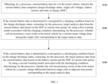
- the current battery data is determined to correspond to a discharging condition based on the charge-discharge status, using a second warning model corresponding to the discharging condition to extract target analysis data from the current battery data based on the battery current and state of charge at various time points: determining whether the cell inconsistency exists in the to-be-tested vehicle or not by a current voltage differential between single cells at adjacent time points corresponding to the target analysis data.
- Embodiments of the present disclosure provides an electronic device, the electronic device including: a processor and a memory.
- the processor by invoking a program or instruction stored in the memory, is configured to execute the steps of the method for detecting inconsistency of single cells of a vehicle battery according to any one of the embodiments.
- Embodiments of the present disclosure provides a computer-readable storage medium, storing a program or instruction, where the program or instruction causes a computer to execute the steps of the method for detecting inconsistency of single cells in a vehicle battery according to any one of the embodiments.
- Embodiments of the present disclosure have the following advantages.
- FIG. 1 is a flowchart of a method for detecting inconsistency of single cells in a vehicle battery according to embodiments of the present disclosure.
- FIG. 2 is a flowchart of a method for determining whether the cell inconsistency exists in the to-be-tested vehicle by a current mean voltage drop among the single cells corresponding to the target analysis data.
- FIG. 3 is a flowchart of a method for whether the cell inconsistency exists in the to-be-tested vehicle by the current voltage differential between the single cells at the adjacent time points corresponding to the target analysis data.
- FIG. 4 is a schematic diagram of an electronic device according to embodiments of the present disclosure.
- One embodiment of the present disclosure provides a method for detecting inconsistency in single cells of a vehicle battery, primarily applicable to platforms, servers, or cloud systems that determine whether a vehicle has inconsistency in single cells based on the received current battery data of a new energy vehicle and issue timely warnings for cell inconsistency.
- the method may be executed by electronic devices integrated into on-board, server, cloud, or platform devices.
- FIG. 1 is a flowchart of a method for detecting inconsistency in single cells of the vehicle battery according to embodiment of the present disclosure.
- the method for detecting inconsistency in single cells of the vehicle battery includes:
- S 110 obtaining current battery data for a to-be-tested vehicle, where the current battery data comprises charge-discharge status, single cell voltages, battery current, and state of charge (SOC).
- the current battery data comprises charge-discharge status, single cell voltages, battery current, and state of charge (SOC).
- the to-be-tested vehicle may be a vehicle currently being identified for the presence of inconsistency in single cells.
- the platform can receive real-time current battery data sent by various to-be-tested vehicles through a Telematics-BOX (T-BOX), a vehicle communication device.
- T-BOX Telematics-BOX
- the current battery data can include charge-discharge status, single cell voltages, battery current, and state of charge (SOC).
- the charge-discharge status may be specifically a charging state or discharging state, representing the state of the battery in the to-be-tested vehicle.
- the single cell voltage may be the actual voltage corresponding to each single cell of the power battery in the to-be-tested vehicle.
- the battery current may be the actual current of the power battery in the to-be-tested vehicle.
- the state of charge may be the actual remaining capacity of the power battery in the to-be-tested vehicle.
- current battery data may also include real-time vehicle speed, location information, and other data.
- determining whether the current battery data for the to-be-tested vehicle corresponds to a charging condition or a discharging condition For example, if the charge-discharge status is a charging state, the current battery data corresponds to a charging condition: if the charge-discharge status is a discharging state, the current battery data corresponds to a discharging condition.
- the current battery data corresponds to a charging condition
- using the first warning model to determine whether the to-be-tested vehicle has inconsistency in single cells may be used to identify the presence of inconsistency in single cells based on the current battery data under charging conditions.
- the first warning model may select a portion of the current battery data as target analysis data from the current battery data. For example, randomly select data from the current battery data at a preset number of time points as target analysis data.
- extracting target analysis data from the current battery data based on the state of charge at various time points in the current battery data includes: obtaining a first preset charge analysis range: based on the first preset charge analysis range selecting time points at which the state of charge is within the first preset charge analysis range in the current battery data; and constructing target analysis data based on the single cell voltages at the selected time points.
- the first preset charge analysis range includes a SOC upper limit and a SOC lower limit.
- the first preset charge analysis range may be SOC in the range of 90-100. It should be noted that selecting SOC in the range of 90-100 as the first preset charge analysis range aims to enhance the detection of inconsistency in single cells when the battery is more prone to malfunction in the charging state within the SOC range of 90-100. This selection allows for efficient analysis while ensuring accuracy.
- time points where the state of charge is within the first preset charge analysis range may be filtered, and then the target analysis data based on the single cell voltages at the filtered time points is constructed.
- time points within the first preset charge analysis range may be selected from the current battery data for subsequent detection of inconsistency in single cells based on the voltages of single cells. This significantly improves analysis efficiency while ensuring accuracy.
- the first warning model may determine the current mean voltage drop among the single cells based on the single cell voltages at various time points in the target analysis data. For example, determine the maximum voltage difference between single cells at each time point, and then use the maximum mean voltage drops at all time points as the current mean voltage drop. Furthermore, inconsistency in single cells may be detected based on the current mean voltage drops.
- the step, determining whether the cell inconsistency exists in the to-be-tested vehicle or not by the current mean voltage drop among the single cells corresponding to the target analysis data includes:
- determining the maximum mean voltage drop between single cells based on the single cell voltages at the time point determining the current mean voltage drop corresponding to the target analysis data based on the maximum mean voltage drop at each time point: determining whether the current mean voltage drop is greater than a first preset threshold. If so, confirming the presence of inconsistency in single cells of the to-be-tested vehicle under the current single charging condition, and generating a first warning signal and transmitting the first warning signal to an associated terminal corresponding to the to-be-tested vehicle.
- U max_v is the maximum cell voltage at time point p
- U min_v is the minimum cell voltage at time point p
- ⁇ U p is the maximum voltage drop at time point p.
- the first warning model may assess whether the current mean voltage drop exceeds the first preset threshold.
- the first preset threshold is a predefined critical value used to determine cell inconsistency during the single charging condition, for example, 60 mV.
- the platform may generate a first warning signal and transmit the first warning signal to the associated terminal of the to-be-tested vehicle to alert the driver to move away from the vehicle promptly or replace the vehicle battery promptly.
- the associated terminal may be a control screen of the vehicle or any user terminal linked to the vehicle, such as the user's smartphone, smartwatch, etc.
- the first warning signal may be in the form of text, voice, or a combination of text and voice, without limitation.
- continuous detection of cell inconsistency under the continuous charging conditions may also be implemented based on real-time battery data.
- determining whether the cell inconsistency exists in the to-be-tested vehicle or not by the current mean voltage drop among the single cells corresponding to the target analysis data further includes: based on a historical battery data from the nearest preset number of historical charging conditions to the current moment determining, at step S 210 , a historical mean voltage drop among cells for each historical charging condition: based on the historical mean voltage drop, the time that each historical charging condition elapsed from the first charging condition, the current mean voltage drop under the current single charging condition, and the time elapsed from the first charging condition to the current single charging condition, constructing, at step S 220 , a mean drop change curve and determining a first slope corresponding to the mean drop change curve: if the first slope of the mean drop change curve is greater than a second preset threshold, and the difference between the maximum and minimum values of the historical and current mean voltage drops is greater than a third preset threshold, determining, at step S 230 , the existence of cell inconsistency under the continuous
- the first warning model can obtain the historical battery data for the to-be-tested vehicle from the nearest preset number of historical charging conditions at the current moment.
- Each historical charging condition may be a single charging condition.
- the historical data from the nearest N1 (e.g., 10 ) historical charging conditions may be obtained.
- the historical mean voltage drop among cells is determined based on the historical battery data for the charging condition.
- the determination method for the historical mean voltage drop may be similar to the method used for the current mean voltage drop.
- the first warning model can plot points with the historical mean voltage drop of the historical charging conditions, the current mean voltage drop of the current single charging condition as a vertical axis, and the time that each historical charging condition elapsed from the first charging condition and the time elapsed from the first charging condition to the current single charging condition as a horizontal axis. Subsequently, a linear fit can be performed based on the plotted points to obtain the mean drop change curve.
- the horizontal axis of the mean drop change curve represents the time elapsed from the first charging condition, and the vertical axis represents the mean voltage drop.
- the mean drip curve can reflect the change in the mean voltage drops under continuous charging conditions.
- the first charging condition may be the first single charging condition obtained by the platform for the to-be-tested vehicle.
- the first warning model can determine the first slope of the mean drop change curve, where the first slope reflects the rate of change in the mean voltage drop over continuous charging conditions.
- the first warning model can determine the presence of cell inconsistency in the to-be-tested vehicle under the continuous charging conditions. At this point, the platform can generate the second warning signal and send the second warning signal to the associated terminal of the to-be-tested vehicle.
- the second preset threshold may be a preset critical value used to detect the rate of change in mean voltage drops under continuous charging conditions, e.g., 0.05.
- the third preset threshold may be a preset critical value for the mean drops used to detect the cell inconsistency under continuous charging conditions, e.g., 40 mV.
- the detection of cell inconsistency is achieved under continuous charging conditions, further ensuring the accuracy of the cell inconsistency detection. This helps avoid the situation of false detection or missed detection of cell inconsistency under single charging conditions due to signal interference. Additionally, based on the trend of changes in continuous charging conditions, potential hazards of the vehicle may be identified earlier, ensuring vehicle safety.
- the second warning model is used to assess whether there is inconsistency in single cells in the to-be-tested vehicle.
- the second warning model may be used to identify the presence of inconsistency in single cells under the discharging condition.
- the second warning model can initially select a portion of data from the current battery data as target analysis data to determine the presence of inconsistency in single cells. For example, randomly select data at a preset number of time points from the current battery data as target analysis data.
- extracting target analysis data from the current battery data based on the battery current and state of charge at various time points includes: obtaining a second preset charge analysis range and a preset current analysis range for current analysis: selecting time points where the state of charge is within the second preset charge analysis range and the battery current is within the preset current analysis range; and constructing the target analysis data based on the voltages of single cells at the selected time points.
- the second preset charge analysis range can include a SOC upper limit and a SOC lower limit.
- the second range for analyzing charge may be SOC in the range of 0-10.
- the current analysis range can include a battery current upper limit and a battery current lower limit.
- the current analysis range may be battery current in the range of 0-5.
- the target analysis data is constructed.
- various time points within the second preset charge analysis range and the preset current analysis range may be selected from the current battery data. This facilitates the subsequent detection of cell inconsistency based on the voltages of the selected time points. This not only ensures analytical accuracy but also significantly improves efficiency.
- determining whether the cell inconsistency exists in the to-be-tested vehicle or not by a current voltage differential between single cells at adjacent time points corresponding to the target analysis data includes the following steps.
- determining the current voltage differentials between the single cells at adjacent time points Based on each of the current voltage differentials, determining a current voltage coefficient of variation (CV) for each cell. Determining a current maximum CV and a current maximum CV difference among all cells based on the current voltage CV of each cell. If the current maximum CV is greater than a fourth preset threshold and the current maximum CV difference is greater than a fifth preset threshold, determining the presence of inconsistency in single cells in the to-be-tested vehicle under the current single discharging condition, and generating and transmitting the first warning signal and to the associated terminal of the to-be-tested vehicle.
- CV current voltage coefficient of variation
- the second warning model can calculate the current voltage CV based on all the current voltage differentials for the cells.
- the current voltage CV describes the fluctuation level of the single cell voltage under the current discharging condition.
- determining the current voltage CV for each cell based on the various current voltage differentials includes: determining a mean voltage differential of each current voltage differential: determining a voltage differential standard deviation based on each current voltage differential and the mean voltage differential; and determining the current voltage CV for each cell based on the mean voltage differential and the voltage differential standard deviation.
- the average value of the current voltage differentials i.e., the mean voltage differential
- the mean voltage differential may be calculated based on all the current voltage differentials for the cells, as follows:
- ⁇ q is the mean voltage differential for the q-th cell
- n represents the number of the time points in the target analysis.
- the voltage differential standard deviation for the cells is calculated. For example:
- ⁇ q is the voltage differential standard deviation for the q-th cell.
- the second warning model can determine the current voltage CV for the cells based on the mean voltage differential and the voltage differential standard deviation, as follows:
- ⁇ a is the current voltage CV for the q-th cell.
- accurately describing the fluctuation level of single cells in the current discharging condition is achieved by calculating the mean voltage differential of all current voltage differentials for each single cell, followed by calculating the voltage differential standard deviation using the mean voltage differential and all current voltage differentials, and determining the current voltage CV for the single cells using the mean voltage differential and the voltage differential standard deviation. This facilitates the detection of cell inconsistency based on the current voltage CV, ensuring detection accuracy.
- the second warning model can identify the current maximum voltage CV as the current maximum CV, and determine the difference between the current maximum and current minimum voltage CVs as a current maximum CV difference.
- the second warning model can assess whether the current maximum CV exceeds the fourth preset threshold, and whether the current maximum CV difference is greater than the fifth preset threshold. If both conditions are met, it indicates the presence of cells with significant fluctuations, and the differences in fluctuation levels among single cells are substantial. This allows the determination that the to-be-tested vehicle exhibits cell inconsistency in the current single discharging condition, prompting the platform to send the first warning signal to the associated terminal.
- the fourth preset threshold may be a predefined CV critical value for detecting inconsistency in single cells under single discharging condition, such as 0.1.
- the fifth preset threshold may be a predefined difference critical value in the single discharging condition, such as 0.1.
- continuous detection of cell inconsistency in multiple discharging conditions may be implemented based on real-time battery data.
- determining whether the cell inconsistency exists in the to-be-tested vehicle or not by a current voltage differential between single cells at adjacent time points corresponding to the target analysis data further includes:
- step S 310 Based on historical battery data from the nearest preset number of historical discharging conditions to the current time, at step S 310 , determining a historical maximum CV and a historical maximum CV difference for each historical discharging condition. Based on the historical maximum CV difference of each historical discharging condition, the time elapsed from the first discharging condition to the each historical discharging conditions, the current maximum CV difference of the current single discharging condition, and the time elapsed from the first discharging condition to the current single discharging condition, constructing, at step S 320 , a CV difference change curve, and determining a second slope corresponding to the CV difference change curve.
- the second slope is greater than a sixth preset threshold, and a maximum value among each historical maximum CV and the current maximum CV is greater than a seventh threshold, then confirming the presence of cell inconsistency in multiple discharging conditions, and generating and transmitting the second warning signal to the associated terminal of the to-be-tested vehicle.
- the second warning model can obtain the historical battery data for the to-be-tested vehicle from the discharging conditions nearest to the current moment.
- Each of the historical discharging conditions may be a single discharging condition. For example, obtaining the historical battery data for the N2 (e.g., 5) most recent discharging conditions nearest to the current moment.
- the second warning model can determine the historical maximum CV and the historical maximum CV difference based on the historical battery data under the each discharging condition.
- the method for determining the historical maximum CV and the historical maximum CV difference can follow the approach used for determining the current maximum CV and the current maximum CV difference.
- the second warning model can plot points with the historical maximum CV difference of each historical discharging condition, the current maximum CV difference of the current single discharging condition as a vertical axis, and the time elapsed from the first discharging condition to each historical discharging condition, and the time elapsed from the first discharging condition to the current single charging condition as a horizontal axis. Subsequently, a linear fit can be performed based on the plotted points to obtain the CV difference change curve.
- the horizontal axis of the CV difference change curve represents the time elapsed from the first discharging condition, and the vertical axis represents the maximum CV difference.
- the CV difference change curve can reflect the fluctuation level of the single cells under continuous discharging conditions.
- the second warning model may determine the second slope corresponding to the CV difference change curve.
- the second slope may reflect the rate of change in fluctuation level of the single cells under continuous discharging conditions.
- the second warning model may determine the existence of cell inconsistency in the to-be-tested vehicle under multiple discharging conditions. In such a case, the platform can generate the second warning signal and transmit the second warning signal to the associated terminal of the to-be-tested vehicle.
- the sixth preset threshold may be a predefined CV difference critical value for detecting cell inconsistency under multiple discharging conditions, such as 0.001.
- the seventh preset threshold may be a predefined maximum CV critical value for detecting cell inconsistency under multiple discharging conditions, such as 0.05.
- detection of cell inconsistency in continuous discharging conditions is realized, further ensuring the accuracy of cell inconsistency detection. It prevents false detections or omissions of cell inconsistency that may occur due to signal interference or other reasons in single discharging conditions. Simultaneously, based on the changing trends of continuous discharging conditions, potential hazards in the vehicle may be detected earlier, ensuring vehicle safety.
- data cleaning may be performed on the current battery data. For example, data points outside a predefined voltage range (e.g., 2-5V) or outside a predefined SOC range (e.g., 0-100) may be excluded. This approach eliminates abnormal data caused by vehicle hardware resource influences, improving the accuracy of detecting single cell inconsistency.
- a predefined voltage range e.g., 2-5V
- a predefined SOC range e.g., 0-100
- the method provided in embodiments of the disclosure divides the current battery data obtained by the platform, combines the characteristics of charging and discharging conditions, and proposes different warning models for different conditions.
- the methods in the prior art employ a unified model and parameters. Processing data collected in both charging and discharging conditions can result in errors in the model calculation, leading to false alarms.
- the method provided in embodiments of the present disclosure proposes different battery inconsistency warning models for two conditions.
- the charging condition the vehicle state is relatively stable, and inconsistency is identified by the difference between the maximum and minimum voltages and their further calculations.
- inconsistency is identified by the differences in the voltage fluctuations over time and their derived calculated values. This approach addresses issues with traditional methods.
- analyzing a portion of the data for inconsistency reduces the computational load of the warning model.
- the method provided in embodiments of the present disclosure can reduce the computational load and improve detection efficiency.
- Single-condition detection often results in false alarms due to occasional data anomalies, and delays in warnings may occur if the data exceeds a threshold.
- Multiple-condition detection avoids false alarms caused by data anomalies and, based on the changing trends of variables in multiple conditions, can detect potential hazards in the vehicle earlier, addressing the issue of delayed warnings in traditional methods based on a single charging or discharging result exceeding a threshold.
- the method for detecting inconsistency in vehicle cells may be executed by hardware devices installed on new energy vehicles.
- the hardware device serves as an independent warning device to ensure driver safety.
- it may be executed by a safety warning cloud platform, which analyzes the results and provides feedback to the vehicle terminal or user terminal.
- the present disclosure has the following advantages: obtaining current battery data for the to-be-tested vehicle, determining whether the current battery data corresponds to a charging condition based on the charge and discharge status in the current battery data. If it does, using the first warning model corresponding to the charging condition to extract target analysis data in the current battery data based on the battery charge status at each time point. Subsequently, the method determines whether there is inconsistency among single cells based on the mean voltage drop between the current cells corresponding to the target analysis data.
- the method uses the second warning model corresponding to the discharging condition to extract target analysis data in the current battery data based on battery current and charge status at each time point, and determines whether there is inconsistency among single cells based on the voltage differential between the current cells at adjacent time points corresponding to the target analysis data.
- This allows for distinguishing between charging and discharging conditions, proposing different warning models for different conditions, achieving separate detection for charging and discharging conditions, improving the accuracy of battery inconsistency warnings, addressing the issue of low detection accuracy in the prior art.
- charging and discharging conditions only a portion of the current battery data is extracted as target analysis data for subsequent detection, reducing the required data volume, thereby reducing the computational load during detection and improving efficiency, addressing the problem of high computational load in existing technologies.
- FIG. 4 is a schematic diagram of an electronic device according to embodiments of the present disclosure. As shown in FIG. 4 , the electronic device 400 includes one or more processors 401 and a memory 402 .
- the processor 401 may be a central processing unit (CPU) or another form of processing unit with data processing and/or instruction execution capabilities. It can control other components in the electronic device 400 to perform desired functions.
- CPU central processing unit
- the processor 401 may be a central processing unit (CPU) or another form of processing unit with data processing and/or instruction execution capabilities. It can control other components in the electronic device 400 to perform desired functions.
- the memory 402 may include one or more computer program products, which can include various forms of computer-readable storage media, such as volatile memory and/or non-volatile memory. Volatile memory, for example, may include random access memory (RAM) and/or cache. Non-volatile memory, for example, may include read-only memory (ROM), hard drives, flash memory, and the like.
- the memory 402 can store one or more computer program instructions, and the processor 401 can run the program instructions to implement the methods for detecting inconsistency in vehicle cells provided in any embodiment of the present disclosure and/or other desired functions.
- the memory 402 may also store various contents, such as initial external parameters, thresholds, and the like.
- the electronic device 400 may further include: an input device 403 and an output device 404 , which are interconnected through a bus system and/or other forms of connection mechanisms (not shown).
- the input device 403 may include, for example, a keyboard, mouse, and the like.
- the output device 404 can output various information to the outside, including warning messages, braking intensity, and the like.
- the output device 404 may include, for example, a display, speaker, printer, communication network, and its connected remote output device, and the like.
- the electronic device 400 may include any other appropriate components.
- embodiments of the present disclosure may also be computer program products comprising computer program instructions that, when executed by a processor, cause the processor to perform the steps of any embodiment of the method for detecting inconsistency in vehicle cells according to the present disclosure.
- the computer program product may be written in one or more programming languages, including object-oriented programming languages such as Java, C++, and the like, and conventional procedural programming languages such as “C.”
- the program code may be executed entirely on a user computing device, partially on a user device, as a standalone software package, partially on a user computing device and partially on a remote computing device, or entirely on a remote computing device or server.
- embodiments of the present disclosure may also be computer-readable storage media containing computer program instructions that, when executed by a processor, cause the processor to perform the steps of any embodiment of the method for detecting inconsistency in vehicle cells provided in the present disclosure.
- the computer-readable storage medium may include one or more combinations of readable media.
- the readable medium may be a readable signal medium or a readable storage medium.
- Readable storage media may include volatile and/or non-volatile media, such as RAM, ROM, electrically erasable programmable read-only memory (EEPROM) or flash memory, or any combination thereof.
- Specific examples of computer-readable storage media include: systems, devices, or apparatuses with one or more conductors, portable disks, hard disks, random access memory (RAM), read-only memory (ROM), erasable programmable read-only memory (EPROM or flash memory), optical fibers, portable compact disc read-only memory (CD-ROM), optical storage devices, and magnetic storage devices or any combination thereof.
- orientation or positional relationships are based on the orientation or positional relationships shown in the drawings for ease of describing the present disclosure and simplifying the description. They do not indicate or imply that the device or element referred to must have a specific orientation, be constructed, or operated in a specific orientation. Therefore, they should not be understood as limiting the present disclosure unless explicitly specified and limited. Terms such as “install,” “connect,” “link,” etc., should be broadly understood.
- they may be fixed connections, detachable connections, or integral connections: they may be mechanical connections or electrical connections: they may be directly connected or indirectly connected through an intermediate medium, and they may be connections within two components.
- Ordinary skilled artisans in the field can understand the specific meanings of these terms in the present disclosure based on specific situations.
Landscapes
- Physics & Mathematics (AREA)
- General Physics & Mathematics (AREA)
- Engineering & Computer Science (AREA)
- Manufacturing & Machinery (AREA)
- Chemical & Material Sciences (AREA)
- Chemical Kinetics & Catalysis (AREA)
- Electrochemistry (AREA)
- General Chemical & Material Sciences (AREA)
- Microelectronics & Electronic Packaging (AREA)
- Secondary Cells (AREA)
- Tests Of Electric Status Of Batteries (AREA)
Abstract
Description
-
- obtaining current battery data corresponding to a to-be-tested vehicle, where the current battery data includes charge-discharge status, single cell voltages, battery current, and state of charge;
- if the current battery data is determined to correspond to a charging condition based on the charge-discharge status, using a first warning model corresponding to the charging condition to extract target analysis data from the current battery data based on the state of charge at various time points: determining whether the cell inconsistency exists in the to-be-tested vehicle or not by a current mean voltage drop among the single cells corresponding to the target analysis data.
ΔU=U max_v −U min_v:
ΔU lp =U t
Claims (8)
Applications Claiming Priority (2)
| Application Number | Priority Date | Filing Date | Title |
|---|---|---|---|
| CN202310293013.1 | 2023-03-24 | ||
| CN202310293013.1A CN116008820B (en) | 2023-03-24 | 2023-03-24 | Detection methods, equipment and media for vehicle battery cell inconsistency |
Publications (2)
| Publication Number | Publication Date |
|---|---|
| US20240319288A1 US20240319288A1 (en) | 2024-09-26 |
| US12174264B2 true US12174264B2 (en) | 2024-12-24 |
Family
ID=86021302
Family Applications (1)
| Application Number | Title | Priority Date | Filing Date |
|---|---|---|---|
| US18/397,957 Active US12174264B2 (en) | 2023-03-24 | 2023-12-27 | Method for detecting inconsistency of single cells in vehicle battery, device and medium |
Country Status (2)
| Country | Link |
|---|---|
| US (1) | US12174264B2 (en) |
| CN (1) | CN116008820B (en) |
Families Citing this family (9)
| Publication number | Priority date | Publication date | Assignee | Title |
|---|---|---|---|---|
| CN116442786B (en) * | 2023-05-30 | 2025-10-17 | 深蓝汽车科技有限公司 | Power battery differential pressure abnormality identification method, device, server and storage medium |
| CN117783872A (en) * | 2023-12-26 | 2024-03-29 | 北汽福田汽车股份有限公司 | Data anomaly detection method, device, server and storage medium for power battery |
| CN117574306B (en) * | 2024-01-17 | 2024-03-22 | 卓然天工自动化仪表(北京)有限公司 | An abnormal value detection method, device and electronic equipment for sensor data |
| CN118731760A (en) * | 2024-06-06 | 2024-10-01 | 东风汽车集团股份有限公司 | Battery voltage consistency judgment method and related equipment |
| CN119974980B (en) * | 2025-02-28 | 2025-11-04 | 奇瑞新能源汽车股份有限公司 | Battery early warning method, device, equipment and readable storage medium |
| CN120468688B (en) * | 2025-05-14 | 2025-10-03 | 安徽大学 | Power battery pack multi-parameter inconsistency detection method based on incremental capacity analysis |
| CN120280585B (en) * | 2025-06-10 | 2025-09-02 | 湖南省国智云科技有限公司 | Energy-saving liquid cooling energy storage method and system |
| CN120565866B (en) * | 2025-07-23 | 2025-10-21 | 江苏智慧优视电子科技有限公司 | A battery operation management system and method based on multi-parameter fusion analysis |
| CN120802073B (en) * | 2025-09-02 | 2025-12-12 | 山东圣阳电源股份有限公司 | UPS high-voltage lithium battery pack operation data acquisition method and system |
Citations (17)
| Publication number | Priority date | Publication date | Assignee | Title |
|---|---|---|---|---|
| FR2961351A1 (en) | 2010-06-15 | 2011-12-16 | Saft Groupe Sa | SYSTEM FOR MONITORING THE STATUS OF A BATTERY |
| CN103081212A (en) * | 2010-06-07 | 2013-05-01 | 丰田自动车株式会社 | Deterioration judgment system and deterioration judgment method of lithium ion secondary battery |
| JP2013213684A (en) * | 2012-03-30 | 2013-10-17 | Toyota Motor Corp | Power storage system and charging state estimation method |
| CN104183878A (en) | 2014-08-19 | 2014-12-03 | 国家电网公司 | Equalized battery access point determination method and device |
| CN107085187A (en) | 2017-04-13 | 2017-08-22 | 华北电力科学研究院有限责任公司 | Echelon utilizes the determination method and device of battery energy storage system consistency maintenance index |
| US20210218257A1 (en) * | 2020-01-09 | 2021-07-15 | Changxing Taihu Electric Corporation | Method for charging a cell, and method and system for charging a battery in full life cycle including pulse charging at an overcharge voltage or an overcharge current |
| WO2021259196A1 (en) * | 2020-06-22 | 2021-12-30 | 北京理工大学 | Battery pack consistency evaluation method and system |
| CN114247663A (en) | 2021-12-20 | 2022-03-29 | 天津仁爱学院 | Method for sorting single batteries for producing lithium ion battery pack |
| WO2022134988A1 (en) * | 2020-12-26 | 2022-06-30 | 华为技术有限公司 | Battery fault detection method, system and apparatus, and device |
| TWI773306B (en) | 2021-05-10 | 2022-08-01 | 加百裕工業股份有限公司 | Method of detecting state of charge of battery |
| CN114879066A (en) | 2022-05-31 | 2022-08-09 | 合肥国轩高科动力能源有限公司 | Battery pack consistency evaluation method and system |
| WO2022174679A1 (en) * | 2021-02-18 | 2022-08-25 | 中国第一汽车股份有限公司 | Method and apparatus for predicting voltage inconsistency fault of battery cells, and server |
| CN115616410A (en) | 2022-09-21 | 2023-01-17 | 岚图汽车科技有限公司 | Battery abnormal self-discharge early warning method, system, electronic equipment and storage medium |
| CN115648944A (en) | 2022-10-25 | 2023-01-31 | 中国汽车技术研究中心有限公司 | Early warning method, device, equipment and storage medium for power battery |
| US20230084779A1 (en) * | 2021-09-11 | 2023-03-16 | Industrial Technology Research Institute | Battery system and protection method thereof |
| US20230236264A1 (en) * | 2022-01-26 | 2023-07-27 | Shanghai Makesens Energy Storage Technology Co., Ltd. | Methods, systems and terminal devices for analyzing cell states based on cell parameters |
| CN114050633B (en) * | 2021-06-11 | 2023-11-10 | 上海玫克生储能科技有限公司 | Dynamic management and control method and device for lithium battery energy storage system and electronic equipment |
-
2023
- 2023-03-24 CN CN202310293013.1A patent/CN116008820B/en active Active
- 2023-12-27 US US18/397,957 patent/US12174264B2/en active Active
Patent Citations (17)
| Publication number | Priority date | Publication date | Assignee | Title |
|---|---|---|---|---|
| CN103081212A (en) * | 2010-06-07 | 2013-05-01 | 丰田自动车株式会社 | Deterioration judgment system and deterioration judgment method of lithium ion secondary battery |
| FR2961351A1 (en) | 2010-06-15 | 2011-12-16 | Saft Groupe Sa | SYSTEM FOR MONITORING THE STATUS OF A BATTERY |
| JP2013213684A (en) * | 2012-03-30 | 2013-10-17 | Toyota Motor Corp | Power storage system and charging state estimation method |
| CN104183878A (en) | 2014-08-19 | 2014-12-03 | 国家电网公司 | Equalized battery access point determination method and device |
| CN107085187A (en) | 2017-04-13 | 2017-08-22 | 华北电力科学研究院有限责任公司 | Echelon utilizes the determination method and device of battery energy storage system consistency maintenance index |
| US20210218257A1 (en) * | 2020-01-09 | 2021-07-15 | Changxing Taihu Electric Corporation | Method for charging a cell, and method and system for charging a battery in full life cycle including pulse charging at an overcharge voltage or an overcharge current |
| WO2021259196A1 (en) * | 2020-06-22 | 2021-12-30 | 北京理工大学 | Battery pack consistency evaluation method and system |
| WO2022134988A1 (en) * | 2020-12-26 | 2022-06-30 | 华为技术有限公司 | Battery fault detection method, system and apparatus, and device |
| WO2022174679A1 (en) * | 2021-02-18 | 2022-08-25 | 中国第一汽车股份有限公司 | Method and apparatus for predicting voltage inconsistency fault of battery cells, and server |
| TWI773306B (en) | 2021-05-10 | 2022-08-01 | 加百裕工業股份有限公司 | Method of detecting state of charge of battery |
| CN114050633B (en) * | 2021-06-11 | 2023-11-10 | 上海玫克生储能科技有限公司 | Dynamic management and control method and device for lithium battery energy storage system and electronic equipment |
| US20230084779A1 (en) * | 2021-09-11 | 2023-03-16 | Industrial Technology Research Institute | Battery system and protection method thereof |
| CN114247663A (en) | 2021-12-20 | 2022-03-29 | 天津仁爱学院 | Method for sorting single batteries for producing lithium ion battery pack |
| US20230236264A1 (en) * | 2022-01-26 | 2023-07-27 | Shanghai Makesens Energy Storage Technology Co., Ltd. | Methods, systems and terminal devices for analyzing cell states based on cell parameters |
| CN114879066A (en) | 2022-05-31 | 2022-08-09 | 合肥国轩高科动力能源有限公司 | Battery pack consistency evaluation method and system |
| CN115616410A (en) | 2022-09-21 | 2023-01-17 | 岚图汽车科技有限公司 | Battery abnormal self-discharge early warning method, system, electronic equipment and storage medium |
| CN115648944A (en) | 2022-10-25 | 2023-01-31 | 中国汽车技术研究中心有限公司 | Early warning method, device, equipment and storage medium for power battery |
Non-Patent Citations (3)
| Title |
|---|
| First Office Action issued in counterpart Chinese Patent Application No. 202310293013.1, dated May 6, 2023. |
| Li et al., Research on Consistency Maintenance Method of Battery Energy Storage System with Hierarchical Utilization, Sino-Global Energy, 2017, 22(4), pp. 89-96, dated Apr. 15, 2017. |
| Zhang et al., Analysis and modeling of nonuniformity characteristics of tractive Li-ion batteries, Chinese Battery Industry, 2008, 13(2), pp. 103-108, dated Apr. 25, 2008. |
Also Published As
| Publication number | Publication date |
|---|---|
| US20240319288A1 (en) | 2024-09-26 |
| CN116008820B (en) | 2023-10-10 |
| CN116008820A (en) | 2023-04-25 |
Similar Documents
| Publication | Publication Date | Title |
|---|---|---|
| US12174264B2 (en) | Method for detecting inconsistency of single cells in vehicle battery, device and medium | |
| CN113310647B (en) | Method and device for detecting leakage of battery pack, electronic equipment and storage medium | |
| CN114148216A (en) | Battery self-discharge rate abnormality detection method, system, device and storage medium | |
| US9767671B2 (en) | System for determining sensor condition | |
| CN104202765B (en) | Transducer-fault Detecting Method and device based on distributed network | |
| CN101720453A (en) | System and method for predictive maintenance of a battery assembly using temporal signal processing | |
| CN112644336B (en) | Power battery thermal runaway prediction method and device | |
| CN110749829B (en) | Power supply equipment abnormality detection method and device | |
| US20220381848A1 (en) | Method and system for detecting vehicle battery cell imbalance | |
| CN110247725A (en) | The line fault investigation method, apparatus and terminal device of OTN network | |
| CN115219935B (en) | New energy equipment health condition assessment method, system, device and medium | |
| CN113985202B (en) | Capacitor fault early warning method and device, electronic equipment and storage medium | |
| CN109033147B (en) | A data presentation method, terminal and computer storable medium | |
| CN115599077A (en) | Vehicle fault delimiting method and device, electronic equipment and storage medium | |
| CN121309045A (en) | A safety early warning method, device and equipment | |
| CN117466153B (en) | Fault detection method, device, computer equipment and readable storage medium | |
| KR20260033095A (en) | Early warning method and device, network device, electric energy device and medium | |
| EP4307205A1 (en) | System for managing battery data, and method therefor | |
| CN119085902A (en) | Method and device for detecting expansion force of battery cell, electronic device and storage medium | |
| CN116719654A (en) | Evaluation method and device of software service, electronic equipment and storage medium | |
| CN114978629A (en) | Safety monitoring, early warning and emergency disposal system based on industrial internet | |
| CN115476684A (en) | Control method, processor, control system and storage medium for engineering vehicle | |
| RU2859097C1 (en) | Method, device and apparatus for vehicle warning, and data carrier | |
| CN120171351B (en) | Method, device, equipment and medium for detecting abnormality of vehicle charging station | |
| KR102636574B1 (en) | The Method and System That Deep Learning-based used Smart Device Rating Management Using Non-destructive Testing |
Legal Events
| Date | Code | Title | Description |
|---|---|---|---|
| AS | Assignment |
Owner name: AUTOMOTIVE DATA OF CHINA CO., LTD., CHINA Free format text: ASSIGNMENT OF ASSIGNORS INTEREST;ASSIGNORS:HE, SHAOQING;WANG, FANG;ZHANG, PENG;AND OTHERS;REEL/FRAME:065965/0270 Effective date: 20231114 Owner name: AUTOMOTIVE DATA OF CHINA (TIANJIN) CO., LTD., CHINA Free format text: ASSIGNMENT OF ASSIGNORS INTEREST;ASSIGNORS:HE, SHAOQING;WANG, FANG;ZHANG, PENG;AND OTHERS;REEL/FRAME:065965/0270 Effective date: 20231114 Owner name: CHINA AUTOMOTIVE TECHNOLOGY AND RESEARCH CENTER CO., LTD., CHINA Free format text: ASSIGNMENT OF ASSIGNORS INTEREST;ASSIGNORS:HE, SHAOQING;WANG, FANG;ZHANG, PENG;AND OTHERS;REEL/FRAME:065965/0270 Effective date: 20231114 |
|
| FEPP | Fee payment procedure |
Free format text: ENTITY STATUS SET TO UNDISCOUNTED (ORIGINAL EVENT CODE: BIG.); ENTITY STATUS OF PATENT OWNER: LARGE ENTITY |
|
| STPP | Information on status: patent application and granting procedure in general |
Free format text: NOTICE OF ALLOWANCE MAILED -- APPLICATION RECEIVED IN OFFICE OF PUBLICATIONS |
|
| STPP | Information on status: patent application and granting procedure in general |
Free format text: PUBLICATIONS -- ISSUE FEE PAYMENT VERIFIED |
|
| STCF | Information on status: patent grant |
Free format text: PATENTED CASE |