US12167166B2 - Multi-channel image receiving device and method - Google Patents
Multi-channel image receiving device and method Download PDFInfo
- Publication number
- US12167166B2 US12167166B2 US17/981,052 US202217981052A US12167166B2 US 12167166 B2 US12167166 B2 US 12167166B2 US 202217981052 A US202217981052 A US 202217981052A US 12167166 B2 US12167166 B2 US 12167166B2
- Authority
- US
- United States
- Prior art keywords
- channel
- image
- network camera
- profile information
- access
- Prior art date
- Legal status (The legal status is an assumption and is not a legal conclusion. Google has not performed a legal analysis and makes no representation as to the accuracy of the status listed.)
- Active
Links
Images


Classifications
-
- H—ELECTRICITY
- H04—ELECTRIC COMMUNICATION TECHNIQUE
- H04N—PICTORIAL COMMUNICATION, e.g. TELEVISION
- H04N7/00—Television systems
- H04N7/12—Systems in which the television signal is transmitted via one channel or a plurality of parallel channels, the bandwidth of each channel being less than the bandwidth of the television signal
-
- H—ELECTRICITY
- H04—ELECTRIC COMMUNICATION TECHNIQUE
- H04N—PICTORIAL COMMUNICATION, e.g. TELEVISION
- H04N21/00—Selective content distribution, e.g. interactive television or video on demand [VOD]
- H04N21/40—Client devices specifically adapted for the reception of or interaction with content, e.g. set-top-box [STB]; Operations thereof
- H04N21/43—Processing of content or additional data, e.g. demultiplexing additional data from a digital video stream; Elementary client operations, e.g. monitoring of home network or synchronising decoder's clock; Client middleware
- H04N21/438—Interfacing the downstream path of the transmission network originating from a server, e.g. retrieving encoded video stream packets from an IP network
- H04N21/4383—Accessing a communication channel
-
- G—PHYSICS
- G06—COMPUTING OR CALCULATING; COUNTING
- G06F—ELECTRIC DIGITAL DATA PROCESSING
- G06F21/00—Security arrangements for protecting computers, components thereof, programs or data against unauthorised activity
- G06F21/30—Authentication, i.e. establishing the identity or authorisation of security principals
- G06F21/44—Program or device authentication
- G06F21/445—Program or device authentication by mutual authentication, e.g. between devices or programs
-
- G—PHYSICS
- G11—INFORMATION STORAGE
- G11B—INFORMATION STORAGE BASED ON RELATIVE MOVEMENT BETWEEN RECORD CARRIER AND TRANSDUCER
- G11B31/00—Arrangements for the associated working of recording or reproducing apparatus with related apparatus
- G11B31/006—Arrangements for the associated working of recording or reproducing apparatus with related apparatus with video camera or receiver
-
- H—ELECTRICITY
- H04—ELECTRIC COMMUNICATION TECHNIQUE
- H04N—PICTORIAL COMMUNICATION, e.g. TELEVISION
- H04N21/00—Selective content distribution, e.g. interactive television or video on demand [VOD]
- H04N21/20—Servers specifically adapted for the distribution of content, e.g. VOD servers; Operations thereof
- H04N21/21—Server components or server architectures
- H04N21/218—Source of audio or video content, e.g. local disk arrays
- H04N21/2187—Live feed
-
- H—ELECTRICITY
- H04—ELECTRIC COMMUNICATION TECHNIQUE
- H04N—PICTORIAL COMMUNICATION, e.g. TELEVISION
- H04N21/00—Selective content distribution, e.g. interactive television or video on demand [VOD]
- H04N21/20—Servers specifically adapted for the distribution of content, e.g. VOD servers; Operations thereof
- H04N21/23—Processing of content or additional data; Elementary server operations; Server middleware
- H04N21/238—Interfacing the downstream path of the transmission network, e.g. adapting the transmission rate of a video stream to network bandwidth; Processing of multiplex streams
- H04N21/2385—Channel allocation; Bandwidth allocation
-
- H—ELECTRICITY
- H04—ELECTRIC COMMUNICATION TECHNIQUE
- H04N—PICTORIAL COMMUNICATION, e.g. TELEVISION
- H04N21/00—Selective content distribution, e.g. interactive television or video on demand [VOD]
- H04N21/20—Servers specifically adapted for the distribution of content, e.g. VOD servers; Operations thereof
- H04N21/27—Server based end-user applications
- H04N21/274—Storing end-user multimedia data in response to end-user request, e.g. network recorder
-
- H—ELECTRICITY
- H04—ELECTRIC COMMUNICATION TECHNIQUE
- H04N—PICTORIAL COMMUNICATION, e.g. TELEVISION
- H04N21/00—Selective content distribution, e.g. interactive television or video on demand [VOD]
- H04N21/40—Client devices specifically adapted for the reception of or interaction with content, e.g. set-top-box [STB]; Operations thereof
- H04N21/41—Structure of client; Structure of client peripherals
- H04N21/422—Input-only peripherals, i.e. input devices connected to specially adapted client devices, e.g. global positioning system [GPS]
- H04N21/4223—Cameras
-
- H—ELECTRICITY
- H04—ELECTRIC COMMUNICATION TECHNIQUE
- H04N—PICTORIAL COMMUNICATION, e.g. TELEVISION
- H04N21/00—Selective content distribution, e.g. interactive television or video on demand [VOD]
- H04N21/40—Client devices specifically adapted for the reception of or interaction with content, e.g. set-top-box [STB]; Operations thereof
- H04N21/41—Structure of client; Structure of client peripherals
- H04N21/426—Internal components of the client ; Characteristics thereof
- H04N21/42684—Client identification by a unique number or address, e.g. serial number, MAC address, socket ID
-
- H—ELECTRICITY
- H04—ELECTRIC COMMUNICATION TECHNIQUE
- H04N—PICTORIAL COMMUNICATION, e.g. TELEVISION
- H04N21/00—Selective content distribution, e.g. interactive television or video on demand [VOD]
- H04N21/40—Client devices specifically adapted for the reception of or interaction with content, e.g. set-top-box [STB]; Operations thereof
- H04N21/45—Management operations performed by the client for facilitating the reception of or the interaction with the content or administrating data related to the end-user or to the client device itself, e.g. learning user preferences for recommending movies, resolving scheduling conflicts
- H04N21/4508—Management of client data or end-user data
- H04N21/4532—Management of client data or end-user data involving end-user characteristics, e.g. viewer profile, preferences
-
- H—ELECTRICITY
- H04—ELECTRIC COMMUNICATION TECHNIQUE
- H04N—PICTORIAL COMMUNICATION, e.g. TELEVISION
- H04N21/00—Selective content distribution, e.g. interactive television or video on demand [VOD]
- H04N21/40—Client devices specifically adapted for the reception of or interaction with content, e.g. set-top-box [STB]; Operations thereof
- H04N21/45—Management operations performed by the client for facilitating the reception of or the interaction with the content or administrating data related to the end-user or to the client device itself, e.g. learning user preferences for recommending movies, resolving scheduling conflicts
- H04N21/458—Scheduling content for creating a personalised stream, e.g. by combining a locally stored advertisement with an incoming stream; Updating operations, e.g. for OS modules ; time-related management operations
-
- H—ELECTRICITY
- H04—ELECTRIC COMMUNICATION TECHNIQUE
- H04N—PICTORIAL COMMUNICATION, e.g. TELEVISION
- H04N23/00—Cameras or camera modules comprising electronic image sensors; Control thereof
- H04N23/90—Arrangement of cameras or camera modules, e.g. multiple cameras in TV studios or sports stadiums
-
- H—ELECTRICITY
- H04—ELECTRIC COMMUNICATION TECHNIQUE
- H04N—PICTORIAL COMMUNICATION, e.g. TELEVISION
- H04N7/00—Television systems
- H04N7/08—Systems for the simultaneous or sequential transmission of more than one television signal, e.g. additional information signals, the signals occupying wholly or partially the same frequency band, e.g. by time division
- H04N7/0806—Systems for the simultaneous or sequential transmission of more than one television signal, e.g. additional information signals, the signals occupying wholly or partially the same frequency band, e.g. by time division the signals being two or more video signals
-
- H—ELECTRICITY
- H04—ELECTRIC COMMUNICATION TECHNIQUE
- H04N—PICTORIAL COMMUNICATION, e.g. TELEVISION
- H04N7/00—Television systems
- H04N7/18—Closed-circuit television [CCTV] systems, i.e. systems in which the video signal is not broadcast
- H04N7/181—Closed-circuit television [CCTV] systems, i.e. systems in which the video signal is not broadcast for receiving images from a plurality of remote sources
-
- H—ELECTRICITY
- H04—ELECTRIC COMMUNICATION TECHNIQUE
- H04W—WIRELESS COMMUNICATION NETWORKS
- H04W12/00—Security arrangements; Authentication; Protecting privacy or anonymity
- H04W12/06—Authentication
- H04W12/068—Authentication using credential vaults, e.g. password manager applications or one time password [OTP] applications
-
- H—ELECTRICITY
- H04—ELECTRIC COMMUNICATION TECHNIQUE
- H04N—PICTORIAL COMMUNICATION, e.g. TELEVISION
- H04N21/00—Selective content distribution, e.g. interactive television or video on demand [VOD]
- H04N21/40—Client devices specifically adapted for the reception of or interaction with content, e.g. set-top-box [STB]; Operations thereof
- H04N21/43—Processing of content or additional data, e.g. demultiplexing additional data from a digital video stream; Elementary client operations, e.g. monitoring of home network or synchronising decoder's clock; Client middleware
- H04N21/438—Interfacing the downstream path of the transmission network originating from a server, e.g. retrieving encoded video stream packets from an IP network
-
- H—ELECTRICITY
- H04—ELECTRIC COMMUNICATION TECHNIQUE
- H04N—PICTORIAL COMMUNICATION, e.g. TELEVISION
- H04N5/00—Details of television systems
- H04N5/76—Television signal recording
- H04N5/765—Interface circuits between an apparatus for recording and another apparatus
- H04N5/77—Interface circuits between an apparatus for recording and another apparatus between a recording apparatus and a television camera
Definitions
- the present disclosure relates to an image receiving device for receiving a channel image from a network camera supporting multiple channels, and more particularly, to an image receiving device and method capable of receiving an image through other channels without registering a separate channel after registering one channel.
- Patent Document 1 Korean Patent Laid-Publication No. 2013-0119248 (Patent Document 1) suggests a technology that may solve an inconvenience of having to manually set the network settings for an NVR and an IP camera one by one for a user without professional knowledge related to IP network settings by implementing an automatic establishment of a connection between the NVR device and the IP camera with minimal user intervention.
- Patent Document 1 has a limit to the use of an automatic registration function of a wireless camera because it is not a fully automated method when connecting between a wireless NVR device and the wireless camera in a connection process before establishing the connection between the wireless NVR device and the wireless camera.
- Patent Document 2 discloses a function of automatically registering wireless cameras in an NVR. According to Patent Document 2, user convenience is improved by automating the connection between the wireless NVR device and the wireless camera in a plug-and-play manner in the connection process before establishing the connection between the wireless NVR device and the wireless camera. Specifically, Patent Document 2 proposes a two-step connection structure in which a virtual connection is sequentially attempted to each wireless NVR device by using an initial connection password for each channel of the NVR, and an actual connection is made when authentication is confirmed.
- the conventional technologies including the above-described technologies suggest a more automated method for registering each channel from the network camera supporting multiple channels, but in order to receive an image from a necessary channel, because the image needs to be received after registering the corresponding channel each time, a procedure is cumbersome and it is difficult to avoid an occurrence of time delays.
- aspects of the present disclosure receive, display, or retransmit an image by setting a virtual channel for channels other than a registered channel when one channel is registered in a multi-channel image receiving device such as a network video recorder in multi-channel termination equipment such as a multi-channel monitoring camera and a multi-channel encoder.
- a multi-channel image receiving device such as a network video recorder in multi-channel termination equipment such as a multi-channel monitoring camera and a multi-channel encoder.
- aspects of the present disclosure also improve asymmetric performance by enabling more channels to be used quickly when performing display or retransmission without storage in a multi-channel image receiving device that has superior display performance or network performance compared to storage performance.
- a multi-channel image receiving method performed by the instructions under the control of the processor, the multi-channel image receiving method includes: receiving, from a network camera supporting a plurality of channels, access information for registering a first channel among the plurality of channels and profile information on a second channel other than the first channel; registering the first channel as a regular channel by using the access information; registering the second channel as a virtual channel by using the profile information; requesting the network camera to transmit an image through the second channel by using the profile information; and receiving and storing the image transmitted from the network camera through the second channel.
- the access information includes an Internet protocol address of the network camera, an access ID, an access password, and the profile information.
- the profile information includes streaming capability and streaming uniform resource identifier (URI).
- URI streaming uniform resource identifier
- An image transmitted through the first channel is an original fisheye image
- the image transmitted through the second channel is a dewarp image of a partial region of the original fisheye image.
- An image transmitted through the first channel is a live image and/or an image for storage, and the image transmitted through the second channel is a live image.
- the streaming capability includes at least one of a communication protocol, a support resolution, a support frame rate, and a support bit rate supported by the second channel.
- the second channel When the second channel is registered as the virtual channel, the second channel is displayed to a user as a hierarchical sub-connection to the first channel.
- the third channel is displayed to the user in parallel with the first channel.
- the multi-channel image receiving method further includes deleting the second channel registered as the virtual channel by deleting the profile information on the second channel stored in the memory.
- a multi-channel image receiving method performed by the instructions under the control of the processor, the multi-channel image receiving method includes: receiving access information on a first channel from a network camera supporting the first channel and a second channel; registering the first channel as a registration channel by using the access information of the first channel; requesting an image of the second channel from the network camera by using the access information of the first channel; and receiving the image of the second channel through the registration channel.
- the multi-channel receiving method further includes retransmitting the image of the second channel to a display and/or another device.
- the access information includes an Internet protocol address of the network camera, an access ID, an access password, and profile information.
- the requesting of the image of the second channel includes requesting the network camera to transmit an image through the second channel by using the access information of the first channel and profile information of the second channel.
- the profile information includes streaming capability and streaming uniform resource identifier (URI).
- URI streaming uniform resource identifier
- the streaming capability includes at least one of a communication protocol, a support resolution, a support frame rate, and a support bit rate supported by the second channel.
- the multi-channel image receiving method further includes receiving an image of the first channel through the registration channel, wherein the image of the first channel is an original fisheye image, and the image of the second channel is a dewarp image of a partial region of the original fisheye image.
- the multi-channel image receiving method further includes receiving an image of the first channel through the registration channel, wherein the image of the first channel is a live image and/or an image for storage, and the image of the second channel is a live image.
- the multi-channel image receiving device such as the network video recorder to receive and display or retransmit all channels of the multi-channel termination equipment, it is possible to quickly receive or stream the image when it is necessary to receive a specific channel depending on the situation.
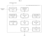
- FIG. 1 is a diagram illustrating a configuration of a monitoring system according to an exemplary embodiment of the present disclosure
- FIG. 2 is a block diagram illustrating a configuration of a network camera according to an exemplary embodiment of the present disclosure
- FIG. 3 is a block diagram illustrating a configuration of a multi-channel image receiving device according to an exemplary embodiment of the present disclosure
- FIG. 4 is a diagram in which channel access information is displayed in a GUI according to an exemplary embodiment of the present disclosure.
- FIG. 5 is a block diagram illustrating the hardware configuration of a computing device that implements a multi-channel image receiving device.
- FIG. 6 is a flowchart illustrating a multi-channel image receiving method performed by the multi-channel image receiving device.
- FIG. 1 is a diagram illustrating a configuration of a monitoring system 200 according to an exemplary embodiment of the present disclosure.
- a monitoring system 200 includes a plurality of network cameras 50 ( 50 A, 50 B, and 50 C), a multi-channel image receiving device 100 , and a user terminal device 30 , and the plurality of network cameras 50 A, 50 B, and 50 C, the multi-channel image receiving device 100 , and the user terminal device 30 are connected to each other through a network 10 such as the Internet or an intranet.
- a representative example of the multi-channel image receiving device may include a network video recorder 100 .
- the present disclosure is not limited thereto.
- the network camera 50 captures an image (monitoring image) of a monitoring area, processes the captured image according to the Internet protocol, and transmits the processed image.
- the network camera 50 may broadcast a LAN ID tag matching a corresponding channel number connected according to a request of the multi-channel image receiving device 200 and receive the Internet protocol address allocated accordingly.
- the multi-channel image receiving device 100 has a built-in network interface connected to the plurality of network cameras 50 , and receives access information such as a channel number of a specific network camera 50 .
- the multi-channel image receiving device 100 may broadcast by allocating an Internet protocol address by using the received channel number.
- the user terminal device 30 may be implemented as a personal computer, a mobile terminal, and the like, and may be connected to the multi-channel image receiving device 200 through the network 10 and receives the monitoring area stored in the multi-channel image receiving device 200 to provide an Internet protocol-based monitoring service.
- FIG. 2 is a block diagram illustrating a configuration of a network camera 50 according to an exemplary embodiment of the present disclosure.
- the network camera 50 may include a processor and a memory for storing instructions executable by the processor, and may include, as functional blocks thereof, an imaging element 51 , a video encoder 52 , a storage 53 , a channel setting unit 54 , an image transmission unit 55 , a network interface 56 , and a control unit 59 that generally controls the functional blocks.
- the imaging element 51 may be implemented by a charge coupled device (CCD) or a complementary metal-oxide semiconductor (CMOS), and captures an external monitoring image and stores the captured image in the storage 52 .
- event information obtained through video analytics (VA) together with the monitoring image may be additionally stored in the storage 52 .
- the event information is metadata capable of expressing contents of an image obtained from the captured image, and includes a type of object, a situation of an event, and the like.
- the captured monitoring image is first encoded by the video encoder 52 for storage efficiency and then stored in the storage 53 .
- the video encoder 52 may embed an image codec such as H.264/AVC, HEVC, or Mpeg-4 for image compression.
- the channel setting unit 54 sets channel information included in the plurality of channels supported by the network camera 50 by using a communication port and a LAN ID.
- the image transmission unit 55 generates a transmission packet from the monitoring image stored in the storage 53 .
- the transmission packet is generated according to a protocol for transmission, and the transmission packet may be generated based on, for example, Transmission Control Protocol/Internet Protocol (TCP/IP) or Real-Time Streaming Protocol (RTSP).
- TCP/IP Transmission Control Protocol/Internet Protocol
- RTSP Real-Time Streaming Protocol
- the network interface 56 includes a physical layer for network communication, transmits access information for channel registration to the multi-channel image receiving device 200 , and transmits a monitoring image to a specific channel according to an image transmission request when receiving the image transmission request through the specific channel from the multi-channel image receiving device 200 .
- FIG. 3 is a block diagram illustrating a configuration of a multi-channel image receiving device 100 according to an exemplary embodiment of the present disclosure.
- the multi-channel image receiving device 100 may include a processor and a memory for storing instructions executable by the processor, and may include, as functional blocks thereof, a network interface 120 , a channel image request unit 125 , a regular channel registration unit 130 , a virtual channel registration unit 135 , a storage 140 , an image forwarding unit 145 , a video decoder 150 , a graphic user interface (GUI) generation unit 155 , an I/O device 160 , and a control unit 59 that generally controls the functional blocks.
- GUI graphic user interface
- the channel image request unit 125 transmits a message requesting image transmission for a specific channel to the network camera 50 through the network interface 120 .
- the channel image request unit 125 requests access information for a corresponding channel from the network camera 50 prior to the image transmission.
- Such access information includes an Internet protocol address of the network camera 50 , channel information, access ID, access password, and profile information.
- a user of the multi-channel image receiving device 100 uses the Internet protocol address for connection to the network camera 50 , and uses a pair of the access ID and the access password to authenticate the access to the network camera 50 .
- the channel information means channel information (channel information, number of channels, and the like) set in the network camera 50 by using the communication port and the LAN ID.
- the profile information means transmission information for actually receiving the transmission packet, such as streaming capability and streaming uniform resource identifier (URI).
- the streaming capability includes options supported by the network camera 50 for image transmission, such as a communication protocol, a support resolution, a support frame rate, and a support bit rate supported by the channel.
- the network interface 120 receives additional information on channels other than the channel supported by the network camera 50 , for example, profile information, together with the access information for registering the channel from the network camera 50 .
- the image receiving device when it is necessary to transmit an image for a certain channel, the image receiving device has to register the corresponding channel one by one. This causes various problems such as not only consuming resources, but also delaying time when an image is requested while changing a channel. Therefore, according to the present disclosure, when access information of a certain channel (first channel) is received for the first time, additional information on other channels that may be supported by network camera 50 than the certain channel in addition to the access information of the first channel is also received. Since unique information on the network camera 50 has already been received when the access information of the first channel is received, such additional information may minimally include only information necessary for image transmission of another channel (second channel), for example, profile information.
- second channel for example, profile information.
- the regular channel registration unit 130 registers the first channel as a normal physical channel by using the access information on the first channel and stores related information in the storage 140
- the virtual channel registration unit 135 registers the second channel as a virtual channel by using additional information on the second channel other than another channel, that is, profile information.
- the profile information means transmission information for actually receiving the transmission packet, such as streaming capability and streaming uniform resource identifier (URI) as described above, and the streaming capability includes options supported by the network camera 50 for image transmission, such as a communication protocol, a support resolution, a support frame rate, and a support bit rate supported by the channel.
- the virtual channel means a “virtual” channel that exists only as a data set in the memory without performing a general registration procedure unlike an actually registered regular channel and is used to equally process the registration of the actual regular channel.
- an original fisheye image may be received through the first channel that is the regular channel, and a dewarp image of a partial region of the original fisheye image may be received through another channel that is the virtual channel. Therefore, the user of the multi-channel image receiving device 100 may receive a distorted original fisheye image through the physical first channel and quickly receive the dewarp image at a specific location through other channels whenever necessary. If the image transmission is frequently requested while changing to any one of the first channel and other channels, it is possible to quickly request and receive the corresponding dewarp image from the network camera 50 only with the profile information stored in the memory as the virtual channel without performing a separate registration procedure, according to the present disclosure.
- an image for storage that is received and stored in the storage 140 may be received through the first channel that is the regular channel, and a live image to be played directly through a display or to be retransmitted to the user terminal device 30 without needing to be permanently/semi-permanently stored may be received through another channel, that is the virtual channel.
- a live image to be played directly through a display or to be retransmitted to the user terminal device 30 without needing to be permanently/semi-permanently stored may be received through another channel, that is the virtual channel.
- the channel image request unit 125 requests the network camera 50 to transmit the image through the second channel by using the profile information stored in the memory. Thereafter, the network interface 120 receives the image transmitted from the network camera through the second channel, and the storage 140 stores the received image.
- the image forwarding unit 145 may regenerate the monitoring image stored in the storage 140 as a retransmission packet and forward the retransmission packet to the user terminal device 30 through the network interface 120 .
- the video decoder 150 generates a restored image by decoding the transmission packet of the monitoring image received from the network camera 50 through the network interface 120 .
- the video decoder 150 may embed an image codec such as H.264/AVC, HEVC, or Mpeg-4 for image restoration.
- the GUI generation unit 155 may display the monitoring image decoded by the video decoder 150 to the user through the I/O device 160 together with a graphic user interface (GUI) through which the user may visually confirm.
- GUI graphic user interface
- the GUI may include access information of a plurality of channels of a specific network camera 50 . For example, when the second channel is registered as the virtual channel, the second channel may be displayed to the user as a hierarchical sub-connection to the first channel.
- the I/O device 160 includes an input/output means capable of interacting with the user, such as a display device such as an LCD and an LED, a touch panel, and a mouse.
- a display device such as an LCD and an LED
- a touch panel such as a touch panel
- a mouse such as a mouse
- FIG. 4 is a diagram in which channel access information is displayed in a GUI according to an exemplary embodiment of the present disclosure.
- the multi-channel image receiving device 100 registers channel information on a camera A and a camera B and displays the channel information in a GUI.
- the camera A has N channels of channels A-1 to A-N
- the camera B has M channels of channels B-1 to B-M.
- all channels of camera A are registered through a regular channel registration process and are thus displayed in parallel, while only the channel B-1 among the channels of the camera B is registered through the regular channel registration process and the remaining channels are registered as the virtual channels.
- all virtual channels B-2 to B-M of the camera B are registered as the virtual channels together in the registration process of the channel B-1. That is, the multi-channel image receiving device 100 receives additional information on the remaining channels when channel B-1 is registered, and stores the received additional information as a data set in the memory. Thereafter, when it is necessary to receive a monitoring image through the channels other than the channel B-1, it is possible to request the monitoring image from the camera B without a separate registration process and to quickly receive the monitoring image.
- a virtual channel generation process (“makeNewNetCam4VC”) may be created, for example, in pseudo code as illustrated in Table 1 below.
- virtual channel information through the registered channel is performed by a “MAKE_VC_CHANNEL(1Ch, subCh)” function.
- 1Ch means a channel that is regularly registered
- subCh means a channel that is registered as a virtual channel as a lower hierarchical structure of the channel.
- a virtual channel deletion process (“deleteNetCam4VC”) may be created, for example, in pseudo code as illustrated in Table 2 below.
- profile information related to the deleted virtual channel is also deleted from the memory.
- the deletion of the virtual channel may be performed through the virtual channel registration unit 135 when the memory is saturated or there is no need to receive the monitoring image through the corresponding virtual channel.
- the process of registering one channel (the first channel) as the regular channel from the network camera supporting a plurality of channels and registering the remaining channels (the second channel) as the virtual channel by using the access information of the regular channel without the registration process as described above has been described.
- the multi-channel image receiving device 100 may receive an image of each channel by regularly registering only one channel (the first channel) and registering the remaining channels (the second channel) as the virtual channels without registration, instead of registering all of the plurality of channels of the network camera 50 .
- the present disclosure is not limited thereto, and another exemplary embodiment is also possible in which the multi-channel image receiving device 100 receives the image through the plurality of channels of the network camera 50 by using access information on the registered regular channel (registration channel) without registering the virtual channel as it is.
- the multi-channel image receiving device 100 may register only one channel among the plurality of channels supported by the network camera 50 and then may request and receive the images of the remaining channels through the registered channel by using the access information of the registered channel.
- the multi-channel image receiving device 100 may perform the following process.
- the network interface 120 receives, from a network camera supporting a plurality of channels, access information on a first channel among the plurality of channels.
- the access information may include an Internet protocol address of the network camera, an access ID, an access password, and the profile information.
- the regular channel registration unit 130 registers the first channel as a registration channel by using the access information of the first channel.
- the channel image request unit 125 requests images of the remaining channels (second channel) among the plurality of channels from the network camera 50 by using the access information of the first channel as it is.
- the channel image request unit 125 may request the network camera 50 to transmit an image through the second channel by using the access information of the first channel and the profile information of the remaining channels.
- the profile information may include streaming capability and streaming uniform resource identifier (URI).
- URI streaming uniform resource identifier
- the streaming capability may include at least one of a communication protocol, a support resolution, a support frame rate, and a support bit rate supported by the second channel.
- the network interface 120 may receive the image of the second channel through the registration channel (the channel regularly registered with respect to the first channel).
- the received image of the second channel may be displayed on a screen by the GUI generation unit 155 or may be retransmitted to another device by the image forwarding unit 145 .
- the image of the first channel may be an original fisheye image
- the image of the second channel may be a dewarp image of a partial region of the original fisheye image.
- one original fisheye image and a plurality of dewarp images processed therefrom may be received through the one registration channel.
- the network camera 50 may be a fisheye camera.
- the image of the first channel may be a live image and/or an image for storage
- the image of the second channel may be a live image.
- the image of the first channel may be an image (e.g., a front image) obtained by imaging an object in a main direction
- the image of the second channel may be an image obtained by imaging an object in a plurality of different directions (e.g., a plurality of images obtained by imaging the object at different angles).
- the network camera 50 may be a multi-sensor camera.
- the multi-channel image receiving device 100 may receive the plurality of images through one channel registered in the multi-channel image receiving device 100 from the network camera 50 that images/generates one image and derivative images related to the image.
- FIG. 5 is a block diagram illustrating the hardware configuration of a computing device 300 that implements a multi-channel image receiving device 100 .
- a computing device 300 includes a bus 320 , a processor 330 , a memory 340 , a storage 350 , an input/output interface 310 , and a network interface 360 .
- the bus 320 is a path for the transmission of data between the processor 330 , the memory 340 , the storage 350 , the input/output interface 310 , and the network interface 360 .
- the processor 330 is an arithmetic processing unit such as a central processing unit (CPU) or a graphics processing unit (GPU).
- the memory 340 is a memory such as a random-access memory (RAM) or a read-only memory (ROM).
- the storage 350 is a storage device such as a hard disk, a solid state drive (SSD), or a memory card.
- the storage 350 may also be a memory such as a RAM or a ROM.
- the input/output interface 310 is an interface for connecting the computing device 300 and an input/output device.
- a keyboard or a mouse is connected to the input/output interface 310 .
- the network interface 360 is an interface for communicatively connecting the computing device 300 and an external device to exchange transport packets with each other.
- the network interface 360 may be a network interface for connection to a wired line or for connection to a wireless line.
- the computing device 300 may be connected to another computing device 300 - 1 via a network 10 .
- the storage 350 stores program modules that implement the functions of the computing device 300 .
- the processor 330 implements the functions of the computing device 300 by executing the program modules.
- the processor 330 may read the program modules into the memory 340 and may then execute the program modules.
- the hardware configuration of the computing device 300 is not particularly limited.
- the program modules may be stored in the memory 340 .
- the computing device 300 may not include the storage 350 .
- the multi-channel image receiving device 100 may at least include the processor 330 and the memory 340 , which stores instructions that can be executed by the processor 330 .
- the multi-channel image receiving device 100 of FIG. 3 in particular, can be driven by executing instructions including a variety of functional blocks or steps included in the multi-channel image receiving device 100 , via the processor 330 .
- FIG. 6 is a flowchart illustrating a multi-channel image receiving method performed by the multi-channel image receiving device 100 .
- the channel image request unit 125 requests access information of a first channel among a plurality of channels from the network camera 50 supporting the plurality of channels (S 60 ). Accordingly, the network interface 120 receives the access information for registering the first channel from the network camera 50 (S 61 ), and at the same time, receives profile information on a second channel other than the first channel (S 62 ).
- the regular channel registration unit 130 registers the first channel as a regular channel by using the access information (S 63 ), and the virtual channel registration unit 135 registers the second channel as a virtual channel by using the profile information on the second channel (S 64 ).
- the channel image request unit 125 requests the network camera 50 to transmit an image through the second channel by using the profile information on the second channel (S 65 ). Then, the network interface 120 receives the image transmitted from the network camera through the second channel, and the storage 140 stores the received image (S 66 ).
- the virtual channel registration unit 135 may also delete the second channel registered as the virtual channel by deleting the profile information on the second channel stored in the memory.
Landscapes
- Engineering & Computer Science (AREA)
- Multimedia (AREA)
- Signal Processing (AREA)
- Databases & Information Systems (AREA)
- Computer Security & Cryptography (AREA)
- Computer Networks & Wireless Communication (AREA)
- Software Systems (AREA)
- Theoretical Computer Science (AREA)
- Power Engineering (AREA)
- Computer Hardware Design (AREA)
- Physics & Mathematics (AREA)
- General Engineering & Computer Science (AREA)
- General Physics & Mathematics (AREA)
- Two-Way Televisions, Distribution Of Moving Picture Or The Like (AREA)
Abstract
Description
| TABLE 1 |
| NetCamera* NetCameraManager::makeNewNetCam4VC(unsigned |
| intlCh, int subCh, EncUsage_t usage ) |
| { |
| NetCamera* pNetCam = getNetCamera( lCh ); |
| if( NULL == pNetCam ) |
| { |
| LOG_WARN( ″Invalid NVR Channel : %u\n″, lCh ); |
| return NULL; |
| } |
| DeviceConnInfo conInfo = pNetCam->getConnInfo( ); |
| if( VIDEO_ENCODER_TYPE::VIDEO_ENCODER_VNP2 != |
| conInfo.getProtocolType( ) ) |
| { |
| LOG_WARN( ″Invalid protocol type : %d\n″, conInfo. |
| getProtocolType( ) ); |
| return NULL; |
| } |
| if( CAM_PROTOCOL::CAM_SAMSUNG != conInfo.GetProtocol( ) ) |
| { |
| LOG_WARN( ″Invalid protocol : %u\n″, conInfo.GetProtocol( ) ); |
| return NULL; |
| } |
| if( pNetCam->isMultiChannelSupported( ) == false ) |
| { |
| LOG_WARN( ″not support multi channel device( %s ).\n″, |
| conInfo.getIP( ).c_str( ) ); |
| return NULL; |
| } |
| if( subCh == conInfo.getMultiChIndex( ) ) |
| { |
| LOG_WARN( ″subchannel(%d) of MDC is already registerd.\n″, |
| conInfo.getMultiChIndex( ) ); |
| return NULL; |
| } |
| conInfo.setMultiChIndex( subCh ); |
| conInfo.SetVirtualCam( true ); |
| pNetCam = makeNewNetCamera( conInfo ); |
| pNetCam->SetOwnerUsage( usage ); |
| std::list<int> chs; |
| int vch = MAKE VC CHANNEL( lCh, subCh ); |
| chs.push back( vch ); |
| pNetCam->setChannels( chs, true ); |
| pNetCam->connect( ); |
| cam_conn_info_list camConnInfo; |
| camConnInfo.cam_conn_info = conInfo; |
| camConnInfo.pNetCam = pNetCam; |
| camConnInfo.chs = chs; |
| pthread_mutex_lock( &m_mutex_curCamlists ); |
| m_curCamlists.push_back( camConnInfo ); |
| pthread_mutex_unlock( &m_mutex_curCamlists ); |
| return pNetCam; |
| } |
| TABLE 2 |
| int NetCameraManager::deleteNetCam4VC( unsigned int lCh, int |
| subCh, bool bForceDelete /*= false*/ ) |
| { |
| int nRet = −1; |
| int nVC = MAKE_VC_CHANNEL( lCh, subCh ); |
| pthread_mutex_lock( &m_mutex_curCamlists ); |
| for( auto it = m_curCamlists.begin( ); it != m_curCamlists.end( ); ) |
| { |
| std::list<int> chs = it->chs; |
| auto find_it = std::find( chs.begin( ), chs.end( ), nVC ); |
| if( find_it == chs.end( ) ) |
| { |
| ++it; |
| continue; |
| } |
| SUNAPINetCamera* pSunapiNetCamera = dynamic_cast< |
| SUNAPINetCamera* >( it->pNetCam ); |
| if( pSunapiNetCamera == NULL ) |
| { |
| ++it; |
| continue; |
| } |
| if( it->pNetCam->getmProfilesCount( ) == 0 ∥ bForceDelete == |
| true ) |
| { |
| int nTotalUsageCount = 0; |
| net::netCamera::NetVirtualCameraLimiter::getInstance( )->DeleteUsage |
| ( nVC, nTotalUsageCount ); |
| deleteNetCamera( it->pNetCam ); |
| it = m curCamlists.erase( it ); |
| nRet = 0; |
| } |
| else |
| { |
| ++it; |
| nRet = 1; |
| } |
| } |
| pthread_mutex_unlock( &m_mutex_curCamlists ); |
| return nRet; |
| } |
Claims (13)
Applications Claiming Priority (2)
| Application Number | Priority Date | Filing Date | Title |
|---|---|---|---|
| KR10-2021-0151450 | 2021-11-05 | ||
| KR1020210151450A KR20230065655A (en) | 2021-11-05 | 2021-11-05 | Apparatus and method for compressing images |
Publications (2)
| Publication Number | Publication Date |
|---|---|
| US20230144726A1 US20230144726A1 (en) | 2023-05-11 |
| US12167166B2 true US12167166B2 (en) | 2024-12-10 |
Family
ID=84330234
Family Applications (1)
| Application Number | Title | Priority Date | Filing Date |
|---|---|---|---|
| US17/981,052 Active US12167166B2 (en) | 2021-11-05 | 2022-11-04 | Multi-channel image receiving device and method |
Country Status (4)
| Country | Link |
|---|---|
| US (1) | US12167166B2 (en) |
| EP (1) | EP4178200A1 (en) |
| KR (1) | KR20230065655A (en) |
| CN (1) | CN116095260B (en) |
Families Citing this family (1)
| Publication number | Priority date | Publication date | Assignee | Title |
|---|---|---|---|---|
| KR20230065655A (en) * | 2021-11-05 | 2023-05-12 | 한화비전 주식회사 | Apparatus and method for compressing images |
Citations (15)
| Publication number | Priority date | Publication date | Assignee | Title |
|---|---|---|---|---|
| KR100783713B1 (en) | 2006-11-28 | 2007-12-07 | 웹게이트 주식회사 | Internet Protocol-based Surveillance System, Internet Protocol Address Allocation Method and Network Camera Operation Method |
| US20080049116A1 (en) * | 2006-08-28 | 2008-02-28 | Masayoshi Tojima | Camera and camera system |
| US20090016622A1 (en) * | 2007-07-13 | 2009-01-15 | Sony Corporation | Image transmitting apparatus, image transmitting method, receiving apparatus, and image transmitting system |
| US20120262576A1 (en) * | 2011-04-14 | 2012-10-18 | Andrew Blough Sechrist | Method And System For A Network Of Multiple Live Video Sources |
| KR20130119248A (en) | 2012-04-23 | 2013-10-31 | 주식회사 아이디스 | System for setting auto connection of ip cameras on a nvr |
| US8630526B1 (en) * | 2002-04-12 | 2014-01-14 | At&T Intellectual Property Ii, L.P. | Method of indexing multimedia content by creating database records that include location data |
| EP2819407A1 (en) | 2013-06-27 | 2014-12-31 | Idis Co., Ltd. | System for automatic connection between NVR and IP camera |
| US20150125124A1 (en) * | 2013-11-01 | 2015-05-07 | Charles W. Dozier | Camera Video Recorder |
| KR20150141095A (en) | 2014-06-09 | 2015-12-17 | 주식회사 아이티엑스시큐리티 | Wireless camera, wireless Network Video Recoder and method for automatic registration ability thereof |
| CN106453370A (en) * | 2016-10-27 | 2017-02-22 | 浙江宇视科技有限公司 | Method and device for allowing IPC to register to NVR |
| US20170289214A1 (en) * | 2016-04-04 | 2017-10-05 | Hanwha Techwin Co., Ltd. | Method and apparatus for playing media stream on web browser |
| US20170339392A1 (en) * | 2016-05-20 | 2017-11-23 | Qualcomm Incorporated | Circular fisheye video in virtual reality |
| US20180176449A1 (en) * | 2016-12-15 | 2018-06-21 | Hanwha Techwin Co., Ltd. | Camera registering apparatus and method |
| KR101904050B1 (en) | 2017-03-21 | 2018-10-04 | 주식회사 세연테크 | A proxy ap-camera and the surveillance system by using the same |
| US20230144726A1 (en) * | 2021-11-05 | 2023-05-11 | Hanwha Techwin Co., Ltd. | Multi-channel image receiving device and method |
Family Cites Families (3)
| Publication number | Priority date | Publication date | Assignee | Title |
|---|---|---|---|---|
| CN105282486A (en) * | 2014-05-30 | 2016-01-27 | 中国电信股份有限公司 | Video monitoring data transmission method, video monitoring data transmission system and NVR (Network Video Recorder) |
| CN109151815A (en) * | 2017-06-15 | 2019-01-04 | 杭州海康威视数字技术股份有限公司 | Equipment cut-in method, apparatus and system |
| CN113133075B (en) * | 2019-12-31 | 2022-09-16 | 杭州萤石软件有限公司 | Channel switching method in wireless grid network and wireless node equipment |
-
2021
- 2021-11-05 KR KR1020210151450A patent/KR20230065655A/en active Pending
-
2022
- 2022-11-02 EP EP22204997.5A patent/EP4178200A1/en active Pending
- 2022-11-04 US US17/981,052 patent/US12167166B2/en active Active
- 2022-11-04 CN CN202211381765.5A patent/CN116095260B/en active Active
Patent Citations (15)
| Publication number | Priority date | Publication date | Assignee | Title |
|---|---|---|---|---|
| US8630526B1 (en) * | 2002-04-12 | 2014-01-14 | At&T Intellectual Property Ii, L.P. | Method of indexing multimedia content by creating database records that include location data |
| US20080049116A1 (en) * | 2006-08-28 | 2008-02-28 | Masayoshi Tojima | Camera and camera system |
| KR100783713B1 (en) | 2006-11-28 | 2007-12-07 | 웹게이트 주식회사 | Internet Protocol-based Surveillance System, Internet Protocol Address Allocation Method and Network Camera Operation Method |
| US20090016622A1 (en) * | 2007-07-13 | 2009-01-15 | Sony Corporation | Image transmitting apparatus, image transmitting method, receiving apparatus, and image transmitting system |
| US20120262576A1 (en) * | 2011-04-14 | 2012-10-18 | Andrew Blough Sechrist | Method And System For A Network Of Multiple Live Video Sources |
| KR20130119248A (en) | 2012-04-23 | 2013-10-31 | 주식회사 아이디스 | System for setting auto connection of ip cameras on a nvr |
| EP2819407A1 (en) | 2013-06-27 | 2014-12-31 | Idis Co., Ltd. | System for automatic connection between NVR and IP camera |
| US20150125124A1 (en) * | 2013-11-01 | 2015-05-07 | Charles W. Dozier | Camera Video Recorder |
| KR20150141095A (en) | 2014-06-09 | 2015-12-17 | 주식회사 아이티엑스시큐리티 | Wireless camera, wireless Network Video Recoder and method for automatic registration ability thereof |
| US20170289214A1 (en) * | 2016-04-04 | 2017-10-05 | Hanwha Techwin Co., Ltd. | Method and apparatus for playing media stream on web browser |
| US20170339392A1 (en) * | 2016-05-20 | 2017-11-23 | Qualcomm Incorporated | Circular fisheye video in virtual reality |
| CN106453370A (en) * | 2016-10-27 | 2017-02-22 | 浙江宇视科技有限公司 | Method and device for allowing IPC to register to NVR |
| US20180176449A1 (en) * | 2016-12-15 | 2018-06-21 | Hanwha Techwin Co., Ltd. | Camera registering apparatus and method |
| KR101904050B1 (en) | 2017-03-21 | 2018-10-04 | 주식회사 세연테크 | A proxy ap-camera and the surveillance system by using the same |
| US20230144726A1 (en) * | 2021-11-05 | 2023-05-11 | Hanwha Techwin Co., Ltd. | Multi-channel image receiving device and method |
Non-Patent Citations (1)
| Title |
|---|
| Extended European Search Report issued Mar. 27, 2023 from the European Patent Office to EP Application No. 22204997.5. |
Also Published As
| Publication number | Publication date |
|---|---|
| KR20230065655A (en) | 2023-05-12 |
| CN116095260A (en) | 2023-05-09 |
| EP4178200A1 (en) | 2023-05-10 |
| US20230144726A1 (en) | 2023-05-11 |
| CN116095260B (en) | 2025-08-19 |
Similar Documents
| Publication | Publication Date | Title |
|---|---|---|
| US12526331B2 (en) | Adaptive media streaming method and apparatus according to decoding performance | |
| US10412130B2 (en) | Method and apparatus for playing media stream on web browser | |
| JP5326234B2 (en) | Image transmitting apparatus, image transmitting method, and image transmitting system | |
| US9172907B2 (en) | Method and apparatus for dynamically adjusting aspect ratio of images during a video call | |
| US20220014574A1 (en) | Data distribution method and network device | |
| TW201811057A (en) | Image frame processing method | |
| US12167166B2 (en) | Multi-channel image receiving device and method | |
| WO2023142714A1 (en) | Video processing collaboration method, apparatus, device, and storage medium | |
| EP3399713B1 (en) | Device, system, and method to perform real-time communication | |
| CN114710568A (en) | Audio and video data communication method, equipment and storage medium | |
| TWI519131B (en) | Video transmission system and transmitting device and receiving device thereof | |
| US20220201245A1 (en) | Methods and system for transmitting content during a networked conference | |
| JP2011147025A (en) | Distribution apparatus, distribution program and distribution method | |
| JP6658504B2 (en) | Imaging device, imaging method, and imaging system | |
| US20250317583A1 (en) | Method and apparatus for transmitting a plurality of data streams, device, and medium | |
| CN114827638A (en) | VR video cloud live broadcast method, device and equipment | |
| CN106210867A (en) | A kind of method and apparatus of data sharing | |
| US11800158B2 (en) | Video production systems and methods | |
| US12483745B2 (en) | Rendering media streams | |
| CN119697424A (en) | Video transmission method, device, equipment and medium | |
| Fraz et al. | Design and implementation of real time video streaming and ROI transmission system using RTP on an embedded digital signal processing (DSP) platform | |
| JP5094826B2 (en) | Unicast redistribution device and packet processing program | |
| WO2025010270A2 (en) | Method and server for producing live video broadcasting from a plurality of video sources | |
| CN117579873A (en) | Code stream data transmission method, system, electronic device and readable storage medium |
Legal Events
| Date | Code | Title | Description |
|---|---|---|---|
| AS | Assignment |
Owner name: HANWHA TECHWIN CO., LTD., KOREA, REPUBLIC OF Free format text: ASSIGNMENT OF ASSIGNORS INTEREST;ASSIGNOR:KO, JONG PIL;REEL/FRAME:061661/0885 Effective date: 20221031 |
|
| FEPP | Fee payment procedure |
Free format text: ENTITY STATUS SET TO UNDISCOUNTED (ORIGINAL EVENT CODE: BIG.); ENTITY STATUS OF PATENT OWNER: LARGE ENTITY |
|
| STPP | Information on status: patent application and granting procedure in general |
Free format text: DOCKETED NEW CASE - READY FOR EXAMINATION |
|
| AS | Assignment |
Owner name: HANWHA VISION CO., LTD., KOREA, REPUBLIC OF Free format text: CHANGE OF NAME;ASSIGNOR:HANWHA TECHWIN CO., LTD.;REEL/FRAME:064549/0075 Effective date: 20230228 |
|
| STPP | Information on status: patent application and granting procedure in general |
Free format text: NON FINAL ACTION MAILED |
|
| STPP | Information on status: patent application and granting procedure in general |
Free format text: RESPONSE TO NON-FINAL OFFICE ACTION ENTERED AND FORWARDED TO EXAMINER |
|
| STPP | Information on status: patent application and granting procedure in general |
Free format text: FINAL REJECTION MAILED |
|
| STPP | Information on status: patent application and granting procedure in general |
Free format text: RESPONSE AFTER FINAL ACTION FORWARDED TO EXAMINER |
|
| STPP | Information on status: patent application and granting procedure in general |
Free format text: NOTICE OF ALLOWANCE MAILED -- APPLICATION RECEIVED IN OFFICE OF PUBLICATIONS |
|
| STCF | Information on status: patent grant |
Free format text: PATENTED CASE |