US12166540B2 - Exchange of data between a NFC reader and a dual NFC interface transponder - Google Patents
Exchange of data between a NFC reader and a dual NFC interface transponder Download PDFInfo
- Publication number
- US12166540B2 US12166540B2 US17/608,666 US202017608666A US12166540B2 US 12166540 B2 US12166540 B2 US 12166540B2 US 202017608666 A US202017608666 A US 202017608666A US 12166540 B2 US12166540 B2 US 12166540B2
- Authority
- US
- United States
- Prior art keywords
- contactless
- reader
- interface
- data
- transponder
- Prior art date
- Legal status (The legal status is an assumption and is not a legal conclusion. Google has not performed a legal analysis and makes no representation as to the accuracy of the status listed.)
- Active, expires
Links
Images


Classifications
-
- H—ELECTRICITY
- H04—ELECTRIC COMMUNICATION TECHNIQUE
- H04B—TRANSMISSION
- H04B5/00—Near-field transmission systems, e.g. inductive or capacitive transmission systems
- H04B5/70—Near-field transmission systems, e.g. inductive or capacitive transmission systems specially adapted for specific purposes
- H04B5/77—Near-field transmission systems, e.g. inductive or capacitive transmission systems specially adapted for specific purposes for interrogation
-
- G—PHYSICS
- G06—COMPUTING OR CALCULATING; COUNTING
- G06F—ELECTRIC DIGITAL DATA PROCESSING
- G06F13/00—Interconnection of, or transfer of information or other signals between, memories, input/output devices or central processing units
- G06F13/38—Information transfer, e.g. on bus
- G06F13/42—Bus transfer protocol, e.g. handshake; Synchronisation
- G06F13/4282—Bus transfer protocol, e.g. handshake; Synchronisation on a serial bus, e.g. I2C bus, SPI bus
- G06F13/4291—Bus transfer protocol, e.g. handshake; Synchronisation on a serial bus, e.g. I2C bus, SPI bus using a clocked protocol
-
- G—PHYSICS
- G06—COMPUTING OR CALCULATING; COUNTING
- G06K—GRAPHICAL DATA READING; PRESENTATION OF DATA; RECORD CARRIERS; HANDLING RECORD CARRIERS
- G06K19/00—Record carriers for use with machines and with at least a part designed to carry digital markings
- G06K19/06—Record carriers for use with machines and with at least a part designed to carry digital markings characterised by the kind of the digital marking, e.g. shape, nature, code
- G06K19/067—Record carriers with conductive marks, printed circuits or semiconductor circuit elements, e.g. credit or identity cards also with resonating or responding marks without active components
- G06K19/07—Record carriers with conductive marks, printed circuits or semiconductor circuit elements, e.g. credit or identity cards also with resonating or responding marks without active components with integrated circuit chips
- G06K19/0701—Record carriers with conductive marks, printed circuits or semiconductor circuit elements, e.g. credit or identity cards also with resonating or responding marks without active components with integrated circuit chips at least one of the integrated circuit chips comprising an arrangement for power management
- G06K19/0707—Record carriers with conductive marks, printed circuits or semiconductor circuit elements, e.g. credit or identity cards also with resonating or responding marks without active components with integrated circuit chips at least one of the integrated circuit chips comprising an arrangement for power management the arrangement being capable of collecting energy from external energy sources, e.g. thermocouples, vibration, electromagnetic radiation
- G06K19/0708—Record carriers with conductive marks, printed circuits or semiconductor circuit elements, e.g. credit or identity cards also with resonating or responding marks without active components with integrated circuit chips at least one of the integrated circuit chips comprising an arrangement for power management the arrangement being capable of collecting energy from external energy sources, e.g. thermocouples, vibration, electromagnetic radiation the source being electromagnetic or magnetic
- G06K19/0709—Record carriers with conductive marks, printed circuits or semiconductor circuit elements, e.g. credit or identity cards also with resonating or responding marks without active components with integrated circuit chips at least one of the integrated circuit chips comprising an arrangement for power management the arrangement being capable of collecting energy from external energy sources, e.g. thermocouples, vibration, electromagnetic radiation the source being electromagnetic or magnetic the source being an interrogation field
-
- G—PHYSICS
- G06—COMPUTING OR CALCULATING; COUNTING
- G06K—GRAPHICAL DATA READING; PRESENTATION OF DATA; RECORD CARRIERS; HANDLING RECORD CARRIERS
- G06K19/00—Record carriers for use with machines and with at least a part designed to carry digital markings
- G06K19/06—Record carriers for use with machines and with at least a part designed to carry digital markings characterised by the kind of the digital marking, e.g. shape, nature, code
- G06K19/067—Record carriers with conductive marks, printed circuits or semiconductor circuit elements, e.g. credit or identity cards also with resonating or responding marks without active components
- G06K19/07—Record carriers with conductive marks, printed circuits or semiconductor circuit elements, e.g. credit or identity cards also with resonating or responding marks without active components with integrated circuit chips
- G06K19/0716—Record carriers with conductive marks, printed circuits or semiconductor circuit elements, e.g. credit or identity cards also with resonating or responding marks without active components with integrated circuit chips at least one of the integrated circuit chips comprising a sensor or an interface to a sensor
- G06K19/0717—Record carriers with conductive marks, printed circuits or semiconductor circuit elements, e.g. credit or identity cards also with resonating or responding marks without active components with integrated circuit chips at least one of the integrated circuit chips comprising a sensor or an interface to a sensor the sensor being capable of sensing environmental conditions such as temperature history or pressure
-
- G—PHYSICS
- G06—COMPUTING OR CALCULATING; COUNTING
- G06K—GRAPHICAL DATA READING; PRESENTATION OF DATA; RECORD CARRIERS; HANDLING RECORD CARRIERS
- G06K19/00—Record carriers for use with machines and with at least a part designed to carry digital markings
- G06K19/06—Record carriers for use with machines and with at least a part designed to carry digital markings characterised by the kind of the digital marking, e.g. shape, nature, code
- G06K19/067—Record carriers with conductive marks, printed circuits or semiconductor circuit elements, e.g. credit or identity cards also with resonating or responding marks without active components
- G06K19/07—Record carriers with conductive marks, printed circuits or semiconductor circuit elements, e.g. credit or identity cards also with resonating or responding marks without active components with integrated circuit chips
- G06K19/0723—Record carriers with conductive marks, printed circuits or semiconductor circuit elements, e.g. credit or identity cards also with resonating or responding marks without active components with integrated circuit chips the record carrier comprising an arrangement for non-contact communication, e.g. wireless communication circuits on transponder cards, non-contact smart cards or RFIDs
-
- G—PHYSICS
- G06—COMPUTING OR CALCULATING; COUNTING
- G06K—GRAPHICAL DATA READING; PRESENTATION OF DATA; RECORD CARRIERS; HANDLING RECORD CARRIERS
- G06K19/00—Record carriers for use with machines and with at least a part designed to carry digital markings
- G06K19/06—Record carriers for use with machines and with at least a part designed to carry digital markings characterised by the kind of the digital marking, e.g. shape, nature, code
- G06K19/067—Record carriers with conductive marks, printed circuits or semiconductor circuit elements, e.g. credit or identity cards also with resonating or responding marks without active components
- G06K19/07—Record carriers with conductive marks, printed circuits or semiconductor circuit elements, e.g. credit or identity cards also with resonating or responding marks without active components with integrated circuit chips
- G06K19/077—Constructional details, e.g. mounting of circuits in the carrier
- G06K19/07749—Constructional details, e.g. mounting of circuits in the carrier the record carrier being capable of non-contact communication, e.g. constructional details of the antenna of a non-contact smart card
- G06K19/07773—Antenna details
- G06K19/07777—Antenna details the antenna being of the inductive type
- G06K19/07779—Antenna details the antenna being of the inductive type the inductive antenna being a coil
-
- G—PHYSICS
- G06—COMPUTING OR CALCULATING; COUNTING
- G06K—GRAPHICAL DATA READING; PRESENTATION OF DATA; RECORD CARRIERS; HANDLING RECORD CARRIERS
- G06K7/00—Methods or arrangements for sensing record carriers, e.g. for reading patterns
- G06K7/10—Methods or arrangements for sensing record carriers, e.g. for reading patterns by electromagnetic radiation, e.g. optical sensing; by corpuscular radiation
- G06K7/10009—Methods or arrangements for sensing record carriers, e.g. for reading patterns by electromagnetic radiation, e.g. optical sensing; by corpuscular radiation sensing by radiation using wavelengths larger than 0.1 mm, e.g. radio-waves or microwaves
- G06K7/10297—Methods or arrangements for sensing record carriers, e.g. for reading patterns by electromagnetic radiation, e.g. optical sensing; by corpuscular radiation sensing by radiation using wavelengths larger than 0.1 mm, e.g. radio-waves or microwaves arrangements for handling protocols designed for non-contact record carriers such as RFIDs NFCs, e.g. ISO/IEC 14443 and 18092
-
- G—PHYSICS
- G06—COMPUTING OR CALCULATING; COUNTING
- G06K—GRAPHICAL DATA READING; PRESENTATION OF DATA; RECORD CARRIERS; HANDLING RECORD CARRIERS
- G06K7/00—Methods or arrangements for sensing record carriers, e.g. for reading patterns
- G06K7/10—Methods or arrangements for sensing record carriers, e.g. for reading patterns by electromagnetic radiation, e.g. optical sensing; by corpuscular radiation
- G06K7/10009—Methods or arrangements for sensing record carriers, e.g. for reading patterns by electromagnetic radiation, e.g. optical sensing; by corpuscular radiation sensing by radiation using wavelengths larger than 0.1 mm, e.g. radio-waves or microwaves
- G06K7/10316—Methods or arrangements for sensing record carriers, e.g. for reading patterns by electromagnetic radiation, e.g. optical sensing; by corpuscular radiation sensing by radiation using wavelengths larger than 0.1 mm, e.g. radio-waves or microwaves using at least one antenna particularly designed for interrogating the wireless record carriers
- G06K7/10336—Methods or arrangements for sensing record carriers, e.g. for reading patterns by electromagnetic radiation, e.g. optical sensing; by corpuscular radiation sensing by radiation using wavelengths larger than 0.1 mm, e.g. radio-waves or microwaves using at least one antenna particularly designed for interrogating the wireless record carriers the antenna being of the near field type, inductive coil
-
- G—PHYSICS
- G06—COMPUTING OR CALCULATING; COUNTING
- G06K—GRAPHICAL DATA READING; PRESENTATION OF DATA; RECORD CARRIERS; HANDLING RECORD CARRIERS
- G06K7/00—Methods or arrangements for sensing record carriers, e.g. for reading patterns
- G06K7/10—Methods or arrangements for sensing record carriers, e.g. for reading patterns by electromagnetic radiation, e.g. optical sensing; by corpuscular radiation
- G06K7/10009—Methods or arrangements for sensing record carriers, e.g. for reading patterns by electromagnetic radiation, e.g. optical sensing; by corpuscular radiation sensing by radiation using wavelengths larger than 0.1 mm, e.g. radio-waves or microwaves
- G06K7/10366—Methods or arrangements for sensing record carriers, e.g. for reading patterns by electromagnetic radiation, e.g. optical sensing; by corpuscular radiation sensing by radiation using wavelengths larger than 0.1 mm, e.g. radio-waves or microwaves the interrogation device being adapted for miscellaneous applications
- G06K7/10376—Methods or arrangements for sensing record carriers, e.g. for reading patterns by electromagnetic radiation, e.g. optical sensing; by corpuscular radiation sensing by radiation using wavelengths larger than 0.1 mm, e.g. radio-waves or microwaves the interrogation device being adapted for miscellaneous applications the interrogation device being adapted for being moveable
- G06K7/10386—Methods or arrangements for sensing record carriers, e.g. for reading patterns by electromagnetic radiation, e.g. optical sensing; by corpuscular radiation sensing by radiation using wavelengths larger than 0.1 mm, e.g. radio-waves or microwaves the interrogation device being adapted for miscellaneous applications the interrogation device being adapted for being moveable the interrogation device being of the portable or hand-handheld type, e.g. incorporated in ubiquitous hand-held devices such as PDA or mobile phone, or in the form of a portable dedicated RFID reader
-
- H—ELECTRICITY
- H04—ELECTRIC COMMUNICATION TECHNIQUE
- H04B—TRANSMISSION
- H04B5/00—Near-field transmission systems, e.g. inductive or capacitive transmission systems
- H04B5/20—Near-field transmission systems, e.g. inductive or capacitive transmission systems characterised by the transmission technique; characterised by the transmission medium
- H04B5/24—Inductive coupling
- H04B5/26—Inductive coupling using coils
- H04B5/263—Multiple coils at either side
-
- H—ELECTRICITY
- H04—ELECTRIC COMMUNICATION TECHNIQUE
- H04B—TRANSMISSION
- H04B5/00—Near-field transmission systems, e.g. inductive or capacitive transmission systems
- H04B5/20—Near-field transmission systems, e.g. inductive or capacitive transmission systems characterised by the transmission technique; characterised by the transmission medium
- H04B5/24—Inductive coupling
- H04B5/26—Inductive coupling using coils
- H04B5/266—One coil at each side, e.g. with primary and secondary coils
-
- H—ELECTRICITY
- H04—ELECTRIC COMMUNICATION TECHNIQUE
- H04B—TRANSMISSION
- H04B5/00—Near-field transmission systems, e.g. inductive or capacitive transmission systems
- H04B5/40—Near-field transmission systems, e.g. inductive or capacitive transmission systems characterised by components specially adapted for near-field transmission
- H04B5/45—Transponders
-
- H—ELECTRICITY
- H04—ELECTRIC COMMUNICATION TECHNIQUE
- H04B—TRANSMISSION
- H04B5/00—Near-field transmission systems, e.g. inductive or capacitive transmission systems
- H04B5/40—Near-field transmission systems, e.g. inductive or capacitive transmission systems characterised by components specially adapted for near-field transmission
- H04B5/48—Transceivers
-
- H—ELECTRICITY
- H04—ELECTRIC COMMUNICATION TECHNIQUE
- H04B—TRANSMISSION
- H04B5/00—Near-field transmission systems, e.g. inductive or capacitive transmission systems
- H04B5/70—Near-field transmission systems, e.g. inductive or capacitive transmission systems specially adapted for specific purposes
- H04B5/72—Near-field transmission systems, e.g. inductive or capacitive transmission systems specially adapted for specific purposes for local intradevice communication
-
- H—ELECTRICITY
- H04—ELECTRIC COMMUNICATION TECHNIQUE
- H04L—TRANSMISSION OF DIGITAL INFORMATION, e.g. TELEGRAPHIC COMMUNICATION
- H04L12/00—Data switching networks
- H04L12/28—Data switching networks characterised by path configuration, e.g. LAN [Local Area Networks] or WAN [Wide Area Networks]
- H04L12/40—Bus networks
- H04L12/40006—Architecture of a communication node
- H04L12/40019—Details regarding a bus master
-
- H—ELECTRICITY
- H04—ELECTRIC COMMUNICATION TECHNIQUE
- H04L—TRANSMISSION OF DIGITAL INFORMATION, e.g. TELEGRAPHIC COMMUNICATION
- H04L12/00—Data switching networks
- H04L12/28—Data switching networks characterised by path configuration, e.g. LAN [Local Area Networks] or WAN [Wide Area Networks]
- H04L12/40—Bus networks
- H04L12/40006—Architecture of a communication node
- H04L12/40032—Details regarding a bus interface enhancer
-
- H—ELECTRICITY
- H04—ELECTRIC COMMUNICATION TECHNIQUE
- H04W—WIRELESS COMMUNICATION NETWORKS
- H04W88/00—Devices specially adapted for wireless communication networks, e.g. terminals, base stations or access point devices
- H04W88/08—Access point devices
- H04W88/10—Access point devices adapted for operation in multiple networks, e.g. multi-mode access points
-
- H—ELECTRICITY
- H04—ELECTRIC COMMUNICATION TECHNIQUE
- H04W—WIRELESS COMMUNICATION NETWORKS
- H04W92/00—Interfaces specially adapted for wireless communication networks
- H04W92/02—Inter-networking arrangements
Definitions
- Embodiments relate to the transfer of data between a contactless communication device, for example a contactless reader, and modules through a contactless transponder comprising a contactless an interface and a wired interface, for example an I 2 C or a SPI interface, connected to the modules external to the transponder.
- a contactless communication device for example a contactless reader
- modules through a contactless transponder comprising a contactless an interface and a wired interface, for example an I 2 C or a SPI interface, connected to the modules external to the transponder.
- Embodiments are particularly applicable to NFC transponders (“Near Field Communication”), for example labels (tags), intended to serve as a bridge between said external contactless communication device (reader), for example a cellular mobile phone, better known under the name of “smartphone” and said modules of an apparatus, for example a sensor without microcontroller, a control apparatus of a motor, or an e-label without microcontroller, without these examples being limiting.
- NFC transponders Near Field Communication
- tags for example labels (tags)
- reader for example a cellular mobile phone
- modules of an apparatus for example a sensor without microcontroller, a control apparatus of a motor, or an e-label without microcontroller, without these examples being limiting.
- Such transponders serving as a gateway may also be called “dynamic transponders” or “dynamic tags.”
- NFC Near Field Communication
- NFC technology is particularly suitable for connecting any type of user device and allows for quick and easy communications.
- a contactless transponder is a transponder capable of exchanging information via an antenna with a contactless reader, according to a contactless communication protocol.
- An NFC transponder which is a contactless transponder, is a transponder compatible with NFC technology.
- NFC technology is an open standard technology platform in ISO/IEC 18092 and ISO/IEC 21481 but incorporates many existing standards such as the Type A and Type B protocols defined in ISO-14443 which can be communication protocols that can be used in NFC technology.
- RFID Radio Frequency IDentification
- the reader When transmitting information between a reader and a transponder, the reader generates a magnetic field via its antenna which is generally in the standards conventionally used, a sine wave (the carrier) at 13.56 MHz.
- the reader uses an amplitude modulation of said carrier.
- the transponder comprises processing means configured to demodulate the received carrier in order to obtain the data transmitted from the reader.
- the reader For an information transmission from the transponder to the reader, the reader generates the magnetic field (the carrier) without modulation.
- the transponder antenna then modulates the field generated by the reader, according to the information to be transmitted.
- the frequency of this modulation corresponds to a subcarrier of said carrier.
- the frequency of this subcarrier depends on the communication protocol used and can be for example equal to 848 kHz.
- This modulation is performed by modifying the load connected to the terminals of the transponder antenna.
- the transponder retro-modulates the wave coming from the reader to transmit information and does not integrate, for the transmission of information, transmission means themselves, or emitter, capable for example of generating its own magnetic field during the broadcast.
- a transponder devoid of transmitter is called passive transponder, as opposed to an active transponder which includes a transmitter.
- a passive transponder is devoid of power because it uses the wave from the reader to power its integrated circuit.
- the passive transponder may incorporate a power supply, for example a battery.
- both the reader and the active transponder In the active mode of operation, both the reader and the active transponder generate an electromagnetic field. Generally, this mode of operation is used when the active transponder is provided with a power source, for example a battery.
- a power source for example a battery.
- Each of the NFC devices transmits the data using a modulation scheme.
- the modulation results in a load modification and this is then referred to as active load modulation communication.
- Embodiments provide passive transponders and active transponders.
- the information or useful data is encapsulated in frames having a format defined according to the type of protocol used.
- the transponder processing means are in particular configured to de-encapsulate the data that will be transferred to the I 2 C interface, and in the opposite direction encapsulate the data coming from the I 2 C interface, in frames that will be transmitted to the reader (“smartphone for example) by contactless communication.
- NFC/RFID dual interface tags are non-volatile memories with both a contactless interface and a wired interface (usually I 2 C).
- the I 2 C interface is slave and connected to an I 2 C master, usually a microcontroller.
- An external reader can transmit data to, and receive data from the microcontroller by communicating through the dynamic tag, then used as a buffer between wireless and wired worlds.
- the microcontroller itself communicates with other devices or modules on board of the application through various interfaces (frequently serial buses like I 2 C).
- an NFC/RFID reader external to an application, may need to communicate with non-NFC/RFID devices, or modules, on board of an application or apparatus, for example: reading data from sensors, updating displays, storing/reading data to/from non-volatile memories, controlling other devices though I/O expenders, reading ADCs values, etc.
- a conventional solution is to use a NFC/RFID dual interface tag TG on board of the application or apparatus APP, connected as I 2 C slave to a microcontroller MCTRL:
- the NFC/RFID reader RD manages the RF communication with the tag TG.
- the NFC/RFID dual interface tag TG acts as a buffer between the NFC/RFID reader RD and the microcontroller MCTRL.
- the microcontroller MCTRL acts as I 2 C master for the non-NFC/RFID devices, and controls all communications with the NFC/RFID tag TG and with non-NFC/RFID devices.
- a microcontroller is driving different devices D 1 -D 4 on board of the application APP through different channels: I 2 C bus, ADC, GPI/O . . . .
- the NFC/RFID dual interface tag TG has two functions:
- the microcontroller is the I 2 C master device of the application and the NFC/RFID tag acts as a slave.
- NFC/RFID reader indirectly accesses application devices through the microcontroller and the NFC/RFID dual interface tag.
- FIG. 1 illustrates an I 2 C bus
- a similar conventional solution is to use a NFC/RFID dual interface tag on board of the application or apparatus, connected as SPI slave to a microcontroller which acts as the SPI master on the SPI bus.
- Application BOM Bact Of Materials cost: the required microcontroller cost is most of the time much higher than all other components of the application (i.e. Dual interface NFC tag+temperature sensor cost much smaller than microcontroller cost)
- FW Firmware
- Application power efficiency the required microcontroller adds additional power consumption to the application.
- Application size the required microcontroller can add several mm 2 to the application size.
- such a new solution may lead to application (apparatus) cost reduction, application power consumption reduction, application development simplification, application maintenance reduction and simplification or application size reduction.
- a system comprising a contactless reader and an apparatus, said apparatus including a contactless transponder (or tag).
- Said transponder is for example a NFC/RFID dual interface transponder.
- Said transponder includes a contactless interface and a wired interface and being configured to communicate with said reader according to a contactless protocol through said contactless interface, said apparatus including a wired communication bus, for example an inter-integrated circuit (I 2 C) bus or a SPI bus or a so called SMBus, connected to said wired interface and at least one module connected to said bus.
- a wired communication bus for example an inter-integrated circuit (I 2 C) bus or a SPI bus or a so called SMBus
- the reader and the transponder are configured so that the reader is the master on said bus during said communication between the reader and the transponder.
- the reader is advantageously configured to directly communicate with the module(s), which are slave modules, through the NFC/RFID dual interface transponder (or tag), i.e. without passing through any microcontroller.
- Said at least one module is also advantageously configured to directly communicate with the reader through said transponder, i.e. without passing through any microcontroller.
- the reader is not directly connected to the wired communication bus, the reader can be considered to be actually the master of the application or the master on the bus, because it initiates commands within frames consistent with said contactless protocol, and those commands will be transformed into commands on the bus consistent with the protocol used on said bus.
- the wired interface of the tag which is actually connected to the bus, is a master interface.
- the reader is the master on the bus through the master wired interface.
- transponder belonging to the system defined above.
- a transponder including a contactless interface and a wired interface and being configured to communicate with a reader according to a contactless protocol through said contactless interface, said wired interface being configured to be connected to a wired communication bus connected to at least one module connected to said bus, the transponder being configured so that the reader is the master on said bus during said communication between the reader and the transponder.
- Said transponder is advantageously a gateway during a direct communication between said reader and said at least one module through said transponder.
- the transponder comprises pass-through means configured to implement a pass-through function for message exchange between the reader and said at least one module.
- said pass-through means is configured to transform commands initiated by the reader within frames consistent with said contactless protocol, into commands on the bus consistent with a protocol used on said bus.
- said pass-through means comprises first volatile memory means configured to buffer data payload of commands coming from the reader through the contactless interface and data payload of responses intended to be sent to the reader through said contactless interface.
- said first volatile memory comprises at least one buffer.
- said pass-through means further comprises second volatile memory means configured to store control data, said pass-through means being configured to implement said pass-through function for message exchange between the reader and said at least one module, on the basis of said control data.
- said second memory means comprises a plurality of registers.
- said control data comprises first control data sent in or deduced from data payloads of some of commands initiated by the reader.
- said pass-through means further comprises
- said second state machine is configured to read said data payload of commands from the first volatile memory means and to execute them on the bus, to manage the clock and all bus protocol signaling information.
- said second state machine is configured to read the bus answers and to store them in the first volatile memory means for them to be read by the first state machine.
- the transponder is configured to implement a half-duplex message exchange mechanism on the side of said contactless interface.
- said bus maybe an PC bus.
- said bus is a SPI bus.
- an apparatus including the transponder as defined and said at least one module.
- a method for managing data exchange between a contactless reader and an apparatus, said apparatus including a contactless transponder, said transponder including a contactless interface and a wired interface, said transponder communicating with said reader according to a contactless protocol through said contactless interface, said apparatus including a wired communication bus connected to said wired interface and at least one module connected to said bus, said method comprising having said reader act as the master on said bus during said communication between the reader and the transponder.
- NFC/RFID reader directly communicates with I 2 C devices on board of application or apparatus through NFC/RFID dual interface tag.
- the NFC/RFID dual interface tag has two functions:
- the NFC/RFID reader is the real I 2 C master of the whole application.
- Energy harvesting can be used to power the whole application.
- An I 2 C pass through function is implemented in a NFC/RFID dual interface tags, based on a buffer, RF/I 2 C state machine means and a few registers in order to remove the need of a microcontroller.
- a NFC/RFID reader can act as the I 2 C master of the application, in place of a microcontroller.
- a half-duplex exchange mechanism allows exchange of messages from NFC/RFID interface and I 2 C interface.
- a volatile memory buffers the I 2 C commands from NFC/RFID interface and the I 2 C responses to NFC/RFID interface, alternatively.
- a state machine reads I 2 C commands data from the buffer and execute them on the I 2 C bus, managing the clock and all I 2 C signaling.
- the state machine reads I 2 C answers and acknowledge bits on the I 2 C bus and store them in the buffer for them to be read by the NFC/RFID interface.
- An internal buffer (volatile memory, FIFO like) is embedded in the dual interface NFC/RFID tag.
- the buffer is half duplex and can be accessed only by one side at a time.
- An I 2 C/RF pass-through state machine is added in the dual interface NFC/RFID tag.
- the state machine controls the SCL clock and SDA data signals of the I 2 C bus.
- Some control registers are added to handle exchange signaling between RF and I 2 C.
- the NFC/RFID reader indicates to the NFC/RFID tag, through RF commands, the number I 2 C of bytes to read.
- the NFC/RFID tag can detect nature of I 2 C command (read or write) by deducting from the number of bytes to read (or reading last bit of first I 2 C command byte).
- I 2 C command read or write
- a specific dedicated RF command for example a specific command for an I 2 C read command and another specific command for an I 2 C write command.
- the NFC/RFID reader transmits I 2 C commands data bytes to the NFC/RFID tag through RF command's data payload. They are stored in the buffer. I 2 C signaling bits are not included.
- the state machine sends those bytes from the buffer to the I 2 C bus, adding proper I 2 C signaling bits.
- the I 2 C clock can be generated by an internal oscillator inside the transponder or can be derived from the RF signal, for example the 13.56 MHz signal sent by the reader.
- the state machine If data bytes are to be read on the I 2 C bus in return (I 2 C read command), the state machine reads them and store them in the buffer.
- the state machine is managing reading/writing of I 2 C signaling bits.
- the I 2 C master state machine is also constantly reading the acknowledge bits and storing the value in a volatile memory bit.
- the NFC/RFID reader is polling the NFC/RFID tag to check if the I 2 C transaction is finished.
- the NFC/RFID reader reads the acknowledge bit value and the content of the buffer if any I 2 C answer is expected.
- An SPI pass through function is implemented in a NFC/RFID dual interface tags, based on a TX and a RX buffer, a shift register, a state machine and a few registers in order to remove the need of a microcontroller.
- a NFC/RFID reader can act as the SPI master of the application, in place of a microcontroller.
- a half-duplex exchange mechanism allows exchange of messages from NFC/RFID interface and SPI interface.
- a half-duplex or a full duplex messages exchange on the side of the wired (SPI) interface maybe implemented.
- two volatile memory buffers the SPI Tx bytes from NFC/RFID interface and the Rx bytes to NFC/RFID interface.
- a state machine reads SPI Tx bytes data from the Tx buffer and send them on the SPI bus, while receiving in the same time the Rx bytes from slave, through s shift register.
- the state machine manages the clock and the slave selection signals.
- the NFC/RFID reader is polling the NFC/RFID tag to check if the SPI transaction is finished.
- the NFC/RFID reader reads Rx buffer to get SPI slave answer.
- FIG. 1 already described, illustrates the prior art
- FIGS. 2 - 25 illustrate embodiments using an I 2 C bus
- FIGS. 26 - 52 illustrate embodiments using a SPI bus.
- a NFC/RFID reader RD can act as the I 2 C master of the application or apparatus APP, in place of a microcontroller.
- the reader RD is configured to directly communicate with slave modules D 1 -D 4 of the apparatus APP through a contactless interface INT 1 of a NFC/RFID dual interface transponder (or tag) TG, i.e. without passing through any microcontroller.
- the reader RD is not directly connected to the I 2 C bus BS, the reader RD can be considered to be actually the master of the application or the master on the I 2 C bus, because it initiates commands within RF frames, and those commands will be transformed into I 2 C commands the I 2 C bus consistent with the I 2 C protocol.
- the I 2 C interface INT 2 of the tag which is actually connected to the I 2 C bus BS, is a master interface.
- the reader is the master on the bus BS through the I 2 C master interface INT 2 .
- NFC/RFID dual interface transponder or tag
- a non-volatile memory NVM for example an EEPROM
- First volatile memory means like a buffer BF (FIFO), to store I 2 C bytes,
- Second volatile memory means including a plurality of registers, for example the following ones:
- a register RGW to store the number of I 2 C bytes to write.
- a register RGD to store the number of I 2 C bytes to read.
- a register RGC (containing one bit) to signal that I 2 C command is present in buffer BF.
- a register RGR (containing one bit) to signal that I 2 C response is present in buffer BF.
- a register RGK (containing one bit) to record Ack bit value. This register RGK is reset on read.
- a state machine SM 2 for I 2 C pass through control.
- Such a tag TG may be realized for example by an integrated circuit or chip, for example from an integrated circuit of the integrated circuits family having the reference ST25 at STMicroelectronics.
- the I 2 C protocol is well known by the man skilled in the art and can be found in the I 2 C specification. Some features of the I 2 C protocol are now reminded.
- the I 2 C bus uses two wires: serial data (SDA) and serial clock (SCL).
- a device acting as a master generates bus clock and initiates communication on the bus, other devices are slaves and respond to the commands on the bus.
- each slave device In order to communicate with specific device, each slave device must have an address which is unique on the bus.
- I 2 C master device does not need an address since no other (slave) device sends commands to the master.
- Both signals SCL and SDA are bidirectional.
- the SDA signal can only change when the SCL signal is low. When the clock is high, the data should be stable.
- Each I 2 C command initiated by master device starts with a START condition and ends with a STOP condition.
- SCL has to be high.
- a high to low transition of SDA is considered as START and a low to high transition as STOP.
- the master can generate a repeated Start. This is equivalent to a normal Start and is usually followed by the slave I 2 C address.
- FIGS. 4 , 5 and 6 illustrate features of the I 2 C protocol.
- data on the I 2 C bus is transferred in 8-bit packets (bytes).
- bytes There is no limitation on the number of bytes, however, each byte must be followed by an acknowledge bit ACK from a slave device. This bit ACK signals whether the slave device is ready to proceed with the next byte.
- the master For all data bits and the acknowledge bit ACK, the master must generate clock pulses. If the slave device does not acknowledge transfer, this means that there is no more data or the device is not ready for the transfer yet. The master device must either generate Stop or Repeated Start condition.
- MSB Most Significant Bit
- each slave device on the bus should have a unique 7-bit address.
- the communication starts with the Start condition, followed by the 7-bit slave address and the data direction bit R/W.
- the master can continue with reading or writing.
- the communication is ended with the Stop condition which also signals that the I 2 C bus is free.
- the master needs to communicate with other slaves it can generate a repeated start with another slave address without generation Stop condition.
- the master only needs to read from the slave device then it simply sends the I 2 C address with the R/W bit set to read. After this the master device starts reading the data. ( FIG. 6 ).
- the master-transmitter becomes a master-receiver and the slave-receiver becomes a slave-transmitter.
- This first acknowledge A is still generated by the slave.
- the master generates subsequent acknowledges.
- the STOP condition is generated by the master, which sends a not-acknowledge just before the STOP condition.
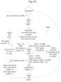
- FIGS. 7 - 11 explain an example of successive steps of the process of writing bytes into a slave module, those bytes being sent by the reader RD in order to be transmitted to a slave module of the apparatus APP.
- the NFC/RFID reader RD sends (step S 7 ) a RF command 700 to the NFC/RFID tag to program the number of I 2 C bytes to be read.
- the RF command 700 has a conventional structure compliant with the used RF protocol, and the number of I 2 C bytes to be read is included in the data payload of the RF command 700 .
- the value of the number of I 2 C bytes to be read is equal to 0 as there is no byte to be read on I 2 C bus.
- This number of I 2 C bytes to be read is extracted from the RF command by the state machine SM 1 (RF pass through control) and written in the register RGD by the state machine SM 1 also (RF pass through control).
- the register RGC and the register RGR contain a 0 value while the register RGK contains a 1 value.
- the NFC/RFID reader RD sends (step S 8 ) a RF write command 800 to the NFC/RFID tag.
- This RF command 800 contains I 2 C bytes to be written on I 2 C bus as well as the I 2 C slave address of the slave module intended for receiving those I 2 C bytes.
- the I 2 C slave address and the I 2 C bytes form a complete I 2 C message intended for being delivering to the I 2 C bus but without I 2 C signaling information, i.e. without here the start and stop conditions.
- the I 2 C slave address which is the first byte, includes the R/W bit which is set to “write”.
- the register RGC is set to 1 by the state machine SM 1 (RF pass through control).
- the state machine SM 1 (RF pass through control) stores the x I 2 C bytes into the buffer BF and updates the register RGW with this I 2 C number x of bytes to write in the designated slave module.
- the I 2 C pass-through state machine SM 2 reads I 2 C bytes from buffer BF and sends them over the I 2 C bus to the corresponding slave module, adding signaling conditions (Start and Stop conditions).
- the register RGC is reset to 0 by the state machine SM 2 .
- the I 2 C pass-through state machine SM 2 reads the Acknowledge bits from I 2 C bus sent by the I 2 C slave module and stores value 0 in the “Ack” register bit RGK.
- the NFC/RFID reader RD sends (step S 10 ) a RF read command 1000 to the NFC/RFID tag to check if I 2 C operation is terminated (polling).
- the RF state machine SM 1 Upon receipt of this RF read command 1000 , the RF state machine SM 1 reads reading the “I 2 C command in buffer” bit contained in the register RGC.
- the value of this bit is sent to the reader RD via a RF response 1001 having a conventional structure compliant with the used RF protocol.
- the NFC/RFID reader RD sends (step S 11 ) a RF read command 1100 to the NFC/RFID tag to read the Acknowledge bit value contained in the register RGK to check if I 2 C write operation was successful.
- the write operation is successful if the Acknowledge bit value is 0.
- this RF command 1100 is processed by the RF state machine SM 1 which reads the value contained in the register RGK, sends it via a RF response 1101 to the reader RD and resets the value of the register RGK to the value 1.
- FIGS. 12 - 17 explain an example of successive steps of a reading process of bytes into a slave module of the apparatus APP in order to be transmitted to the NFC/RFIG reader RD.
- the NFC/RFID reader RD sends (step S 12 ) a RF command 1200 to the NFC/RFID tag to program the number X of I 2 C bytes to be read on the I 2 C bus.
- the value of X is greater than 0 (some byte to be read on I 2 C bus).
- the RF command 1200 has a conventional structure compliant with the used RF protocol, and the number X of I 2 C bytes to be read is included in the data payload of the RF command 700 .
- This number X of I 2 C bytes to be read is extracted from the RF command by the state machine SM 1 (RF pass through control) and written in the register RGD by the state machine SM 1 also (RF pass through control).
- the register RGC and the register RGR contain a 0 value while the register RGK contains a 1 value.
- the NFC/RFID reader RD sends (step S 13 ) a write command 1300 to the NFC/RFID tag TG.
- This RF command 1300 contains the I 2 C slave address of the slave module intended to be read.
- the I 2 C slave address form a complete I 2 C message intended for being delivering to the I 2 C bus but without I 2 C signaling information, i.e. without here the start and stop conditions.
- the I 2 C slave address includes the R/W bit which is set to “read”.
- the register RGC is set to 1 by the state machine SM 1 (RF pass through control).
- the state machine SM 1 (RF pass through control) stores the I 2 C slave address into the buffer BF.
- the I 2 C pass-through state machine SM 2 reads I 2 C slave address byte from buffer BF and sends it over the I 2 C bus through I 2 C interface INT 2 , adding signaling information (Start conditions and acknowledgment bits Acks).
- the register RGC is reset to 0 by the state machine SM 2 .
- the I 2 C pass-through state machine SM 2 reads the Acknowledge bit Ack from I 2 C bus and store value 0 in the “Ack” register bit RGK.
- the I 2 C pass-through state machine reads all bytes from 1 to X from I 2 C bus, store them in the buffer BF, and sends Acks, Nack and Stop condition.
- the register RGR is set to 1 by the state machine SM 2 .
- the NFC/RFID reader RD sends (step S 15 ) a read command 1500 to the NFC/RFID tag TG to check if I 2 C operation is terminated (polling).
- the RF state machine SM 1 Upon receipt of this RF read command 1500 , the RF state machine SM 1 reads reading the “I 2 C response in buffer” bit contained in the register RGR.
- the value of this bit is sent to the reader RD via a RF response 1501 having a conventional structure compliant with the used RF protocol.
- the NFC/RFID reader RD sends (step S 16 ) a read command 1600 to the NFC/RFID tag to read the Acknowledge bit value contained in the register RGK to check if the slave module select operation was successful.
- the slave module select operation is successful if the Acknowledge bit value is 0.
- this RF command 1600 is processed by the RF state machine SM 1 which reads the value contained in the register RGK, sends it via a RF response 1601 to the reader RD and resets the value of the register RGK to the value 1.
- the NFC/RFID reader RD sends (step S 17 ), a read command 1700 to the NFC/RFID tag TG to read the I 2 C bytes response contained in the buffer BF.
- this RF command 1700 is processed by the RF state machine SM 1 , which then sends the I 2 C byte1-I 2 C byteX in the payload data of a RF response 1601 to the reader RD and toggles the value of the register RGR to the value 0.
- the registers RGD, RGW, RGC, RGR, RGK contain control (called also configuration) data (one or several bits) which permit for example to determine the presence or the absence of an operation to be executed, the type of operation (write or read operation) or the status of the operation (terminated for example) or the result of the operation (successful for example).
- registers RGD, RGW and RGC are written by the RF state machine SM 1 .
- the register RGC contains value 0, it means that there is no I 2 C command to be executed by the I 2 C state machine SM 2 .
- the register RGC contains value 1, it means that there is an I 2 C command to be executed by the I 2 C state machine SM 2 , this command being either a write operation or a read operation.
- the type of operation (read or write) is determined by the contents of registers RGD and RGW.
- the operation requested by the reader is a write operation.
- the operation requested by the reader is a read operation.
- the register RGW and the register RGD are also read by the state machine SM 2 to know the number of bytes to write or read in the designated slave module.
- the register RGC is also read by the state machine SM 2 to know if a command is to be executed on the bus and also written by the state machine SM 2 when the execution of the command has started.
- the register RGC is also read by the state machine SM 1 upon request of the reader to know if the execution of a requested command is terminated.
- the register RGR is written by the state machine SM 2 to indicate that read bytes are stored in the buffer BF, and the register RGR is also read by the state machine SM 1 upon request of the reader to check if the I 2 C read operation is terminated.
- the register RGK (for example initially set to 1) is written by the state machine SM 2 upon reception of Ack bits, read by the state machine SM 1 upon request of the reader RD to check whether the read or write operation is successful, and reset to 1 by the state machine SM 1 .
- the data contained in registers RGD and RGW are first control data sent within or deduced from the data payload of the commands sent by the reader and defining if a command from the reader is a write operation or a read operation in the designated slave module.
- the data contained in register RGC is a control data defining the presence or the absence of an operation to be executed on said bus.
- the data contained in register RGC is also a control data indicating whether the execution of a write operation requested by the reader is terminated and the data contained in register RGR is a control data indicating whether the execution of a read operation requested by the reader is terminated.
- the data contained in register RGR is also a control data indicating whether the result of a read operation requested by the reader is stored in the transponder.
- the data contained in the register RGK is a control data indicating whether a read or write operation requested by the reader is successful.
- FIG. 18 details an example of the RF pass through state machine SM 1 and FIG. 19 details an example of PC pass through state machine SM 2 , both permitting to implement the steps disclosed in FIGS. 7 - 17 .
- FIGS. 20 - 25 illustrate examples of apparatuses according to embodiments using an PC bus and a contactless transponder or tag according to embodiments, for example a tag or contactless transponder referenced ST25DV within the STMicroelectronics company having an integrated circuit modified for incorporating means of the embodiments.
- FIG. 20 illustrates a sensor 2000 without MCU (microcontroller).
- FIG. 21 illustrates a door lock 2100 .
- FIG. 22 illustrates GPI/O extension 2200 .
- FIG. 23 illustrates an analog sensor 2300 without MCU.
- FIG. 24 illustrates e-Label 2400 without MCU.
- FIG. 25 illustrates a very big memory tag 2500 .
- UHF ISO18000-6, ISO18000-63, EPC Gen2.
- SPI Serial Peripheral Interface
- a NFC/RFID reader RD 1 can act as the SPI master of the application or apparatus APP 1 , in place of a microcontroller.
- the reader RD 1 is configured to directly communicate with slave modules D 10 -D 40 of the apparatus APP 1 through a contactless interface INT 10 of a NFC/RFID dual interface transponder (or tag) TG 1 , i.e. without passing through any microcontroller.
- the reader RD 1 is not directly connected to the SPI bus BS 1 , the reader RD 1 can be considered to be actually the master of the application or the master on the SPI bus, because it initiates commands within RF frames, and those commands will be transformed into SPI commands the SPI bus consistent with the SPI protocol.
- the SPI interface INT 20 of the tag which is actually connected to the SPI bus BS 1 , is a master interface.
- the reader is the master on the bus BS 1 through the SPI master interface INT 20 .
- NFC/RFID dual interface transponder (or tag) TG 1 integrates:
- the SPI protocol is well known by the man skilled in the art.
- the master is connected to one or more slaves through 4 (in a full-duplex transmission mode) or more lines:
- MOSI Master Output Slave Input to transmit data to a slave.
- MISO Master Input Slave Output to receive data from a slave.
- SS Slave Select line, (active low to select the slave).
- SPI can be set up to operate with a single master and a single slave, and it can be set up with multiple slaves controlled by a single master.
- the clock signal SCLK synchronizes the output of data bits from the master to the sampling of bits by the slave. One bit of data is transferred in each clock cycle, so the speed of data transfer is determined by the frequency of the clock signal. SPI communication is always initiated by the master since the master configures and generates the clock signal.
- the master can choose which slave it wants to talk to by setting the slave's SS line to a low voltage level. In the idle, non-transmitting state, the slave select line is kept at a high voltage level.
- the master sends data to the slave bit by bit, in serial through the MOSI line.
- the slave receives the data sent from the master at the MOSI pin.
- Data sent from the master to the slave is usually, but not compulsorily, sent with the most significant (MSB) bit first.
- the slave can also send data back to the master through the MISO line in serial.
- the data sent from the slave back to the master is usually sent with the least significant (LSB) bit first.
- the SPI bus is full duplex based on exchange of data in a shift register.
- Bits from the slave shift register are pushed in the master shift register at the same time.
- data is sampled on SCLK, with configurable phase CPHA and polarity CPOL.
- the clock signal SCLK in SPI can be modified using the properties of clock polarity and clock phase. These two properties work together to define when the bits are output and when they are sampled.
- Clock polarity can be set by the master to allow for bits to be output and sampled on either the rising or falling edge of the clock cycle.
- Clock phase can be set for output and sampling to occur on either the first edge or second edge of the clock cycle, regardless of whether it is rising or falling.
- the steps for SPI data transmission are the following ones:
- the master outputs the clock signal;
- the master switches the SS pin to a low voltage state, which activates the slave;
- the master sends the data one bit at a time to the slave along the MOSI line.
- the slave reads the bits as they are received; If a response is needed, the slave returns data one bit at a time to the master along the MISO line.
- the master reads the bits as they are received.
- FIGS. 31 to 36 illustrate an example of a SPI full duplex transmission mode implemented by the system SYS 1 according to embodiments.
- the NFC/RFID reader RD 1 sends (step S 31 ) a RF write command 3100 to the NFC/RFID tag to configure the SPI bus by writing the SPI configuration into the SPI configuration register RGCF.
- SPI configuration contains the following information:
- the RF command 3100 has a conventional structure compliant with the used RF protocol, and the configuration information is included in the data payload of the RF command 3100 .
- This configuration information is extracted from the RF command by the state machine SM 10 (RF pass through control) and written in the register RGCF by the state machine SM 10 also (RF pass through control).
- the register RGRT and the register RGTC contain a 0 value.
- the NFC/RFID reader RD 1 sends (step S 32 ) a RF write command 3200 to the NFC/RFID tag TG 1 .
- This RF command 3200 contains SPI bytes to be transmitted on SPI bus.
- the register RGRT is set to 1 by the state machine SM 10 (RF pass through control).
- the state machine SM 10 (RF pass through control) updates the counter DCNT with the number X of bytes to transmit on the SPI bus and writes into Tx buffer the X SPI bytes to be transmitted.
- step S 33 As illustrated in FIG. 33 , once SPI Tx ready bit contained in register RGRT is set to 1, the SPI pass-through state machine SM 20 does (step S 33 ):
- the SPI pass-through state machine SM 20 sets (step S 34 ) the SPI Rx complete bit of the register RGTC to 1 and clears the SPI ready to Tx bit of the register RGRT to 0.
- Rx buffer BFR now contains all the received bytes.
- Tx buffer is empty (SPI data counter DCNT is null).
- SS line is set to high to deselect the SPI slave.
- this RF command 3500 is processed by the RF state machine SM 10 which reads the value contained in the register RGTC and sends it via a RF response 3501 to the reader RD 1 .
- the NFC/RFID reader RD 1 sends (step S 36 ) a read command 3600 to the NFC/RFID tag TG 1 to read the SPI received bytes in the Rx buffer BFR.
- this RF command 3600 is processed by the RF state machine SM 10 which reads the bytes contained in the Rx buffer BFR and sends them via a RF response 3601 to the reader RD 1 .
- the NFC/RFID tag TG 1 is now ready for a new SPI transmission.
- FIGS. 37 to 44 illustrate an example of a SPI half-duplex transmission implemented by the system SYS 1 according to embodiments.
- the SPI state machine SM 20 controls the direction of the output/input pin from/into the shift register SR.
- the NFC/RFID reader RD 1 sends (step S 37 ) a RF write command 3700 to the NFC/RFID tag TG 1 to configure the SPI bus by writing the SPI configuration into the SPI configuration register RGCF.
- SPI configuration contains the following information:
- the RF command 3700 has a conventional structure compliant with the used RF protocol, and the configuration information is included in the data payload of the RF command 3700 .
- This configuration information is extracted from the RF command by the state machine SM 10 (RF pass through control) and written in the register RGCF by the state machine SM 1 also (RF pass through control).
- the register RGRT and the register RGTC contain a 0 value.
- the NFC/RFID reader RD 1 sends (step S 38 ) a RF write command 3800 to the NFC/RFID tag TG 1 .
- This RF command 3800 contains the number of SPI bytes to transmit on SPI bus.
- the state machine SM 10 (RF pass through control) updates the counter TXCNT with the number of bytes to transmit on the SPI.
- the number of bytes to transmit corresponds to the number of byte that will be sent from the master to the slave.
- the SPI data line is configured as output during this time. Once this number of bytes has been transmitted, the SPI line is configured as input to receive the remaining number of bytes counted by SPI data counter register DCNT.
- the NFC/RFID reader RD 1 sends (step S 39 ) a RF write command 3900 to the NFC/RFID tag TG 1 .
- This RF command 3900 contains SPI bytes to be transmitted on SPI bus.
- the register RGRT is set to 1 by the state machine SM 10 (RF pass through control).
- the state machine SM 10 (RF pass through control) writes into Tx buffer BFR the SPI bytes to be transmitted on the SPI bus and updates the counter DCNT with the number of bytes stored in the Tx buffer BFT. This represent the total number of bytes that goes through the SPI bus in output and input.
- NFC/RFID reader RD 1 has to put “dummy” Tx bytes to reflect the total number of bytes transmitted in output and input.
- step S 40 As illustrated in FIG. 40 , once SPI Tx ready bit contained in register RGRT is set to 1, the SPI pass-through state machine SM 20 does (step S 40 ):
- the SPI pass-through state machine SM 20 sets (step S 41 ) the SPI data line to input and starts receiving the Rx bytes 4100 .
- the state machine SM 20 reads the line from the slave and copies the SPI received bytes from the shift register SR into the Rx buffer BFR, and decreases SPI data counter DCNT and loop until it is null.
- the SPI pass-through state machine SM 20 sets (step S 42 ) the SPI Rx complete bit of the register RGTC to 1 and clears the SPI ready to Tx bit of the register RGRT to 0.
- Rx buffer BFR now contains all the received bytes.
- Tx buffer is empty (SPI data counter DCNT is null).
- SS line is set to high to deselect the SPI slave.
- the NFC/RFID reader RD 1 sends (step S 43 ) a RF read command 4300 to the NFC/RFID tag TG 1 to read the “SPI Rx complete” bit contained in the register RGTC to check if SPI operation is terminated. If value is 1, the SPI write operation is over.
- this RF command 4300 is processed by the RF state machine SM 10 which reads the value contained in the register RGTC and sends it via a RF response 4301 to the reader RD 1 .
- the NFC/RFID reader RD 1 sends (step S 44 ) a read command 4400 to the NFC/RFID tag TG 1 to read the SPI received bytes in the Rx buffer BFR.
- this RF command 4400 is processed by the RF state machine SM 10 which reads the bytes contained in the Rx buffer BFR and sends them via a RF response 4401 to the reader RD 1 .
- the NFC/RFID tag TG 1 is now ready for a new SPI transmission.
- the registers RGCF, RGRT, RGTC, DCNT, TXCNT contain control (called also configuration) data (one or several bits) which permit for example to determine the SPI configuration, or to indicate a status “ready to transmit” or the status of the operation (terminated for example) or numbers of bytes to transmit.
- registers RGCF, RGRT, DCNT, TXCNT and RGTC are written by the RF state machine SM 10 .
- the register RGRT contains value 0, it means that there is no SPI command to be executed by the SPI state machine SM 20 .
- register RGRT contains value 1, it means that there is a SPI command to be executed by the SPI state machine SM 20 .
- the number of bytes to transmit on the SPI bus is determined by the contents of registers DCNT and eventually TXCNT.
- registers DCNT and TXCNT are also read by the state machine SM 20 .
- the register RGRT is also read by the state machine SM 20 to know if a command is to be executed on the bus and also written by the state machine SM 20 when the execution of the command is terminated.
- the register RGTC is written by the SPI state machine SM 20 when the execution of the command is terminated and is read by the state machine SM 10 upon request of the reader to know if the execution of a requested command is terminated.
- This register RGTC is also reset by the state machine SM 10 .
- the data contained in registers RGCF, DCNT and TXCNT are first control data sent within or deduced from data payloads of commands sent by the reader.
- FIG. 45 details an example of the RF pass through state machine SM 10 and FIG. 46 details an example of SPI pass through state machine SM 20 , both permitting to implement the steps disclosed in FIGS. 31 - 44 .
- FIGS. 47 - 52 illustrate examples of apparatuses according to embodiments using a SPI bus and a contactless transponder or tag according to embodiments, for example a tag or contactless transponder referenced ST25DV within the STMicroelectronics company having an integrated circuit modified for incorporating means of the embodiments.
- FIG. 47 illustrates a sensor 4700 without MCU.
- FIG. 48 illustrates a door lock 4800 .
- FIG. 49 illustrates GPI/O extension 4900 .
- FIG. 50 illustrates an analog sensor 5000 without MCU.
- FIG. 51 illustrates e-Label 5100 without MCU.
- FIG. 52 illustrates a very big memory tag 5200 .
Landscapes
- Engineering & Computer Science (AREA)
- Physics & Mathematics (AREA)
- Computer Networks & Wireless Communication (AREA)
- Theoretical Computer Science (AREA)
- General Physics & Mathematics (AREA)
- Health & Medical Sciences (AREA)
- Toxicology (AREA)
- Signal Processing (AREA)
- Electromagnetism (AREA)
- Computer Hardware Design (AREA)
- Microelectronics & Electronic Packaging (AREA)
- Computer Vision & Pattern Recognition (AREA)
- Artificial Intelligence (AREA)
- General Health & Medical Sciences (AREA)
- General Engineering & Computer Science (AREA)
- Computer Security & Cryptography (AREA)
- Information Transfer Systems (AREA)
- Bus Control (AREA)
Abstract
Description
-
- a first state machine configured to cooperate with said reader through the contactless interface and configured to write/read said first memory means and a part of said second memory means based on commands received from the reader,
- a second state machine configured to cooperate with said bus through said wired interface based on the content of a part of said second memory means and configured to write/read said first memory means and a part of said second memory means.
-
- said commands initiated by the reader comprises at least one request of a write operation into said at least one module or at least one request of a read operation into said at least one module;
- said at least one request of a write operation into said at least one module comprises the address of said at least one module and the data to be written in said at least one module, and said at least one request of a read operation into said at least one module comprises the number of bytes to read and the address of said at least one module;
- said first control data comprises data defining if a command from the reader is a write operation or a read operation in said at least one module;
- said control data comprises data chosen among
- data defining the presence or the absence of an operation to be executed on said bus,
- data indicating whether the execution of a read operation requested by the reader is terminated,
- data indicating whether the result of a read operation requested by the reader is stored in the transponder,
- data indicating whether a read or write operation requested by the reader is successful.
-
- the transponder maybe configured to implement a half-duplex or a full duplex message exchange mechanism on the side of said wired interface;
- said commands initiated by the reader comprises at least one write command or at least one request of a read command;
- said first control data comprises data defining configuration of the SPI bus;
- said control data comprises data indicating a status “ready to transmit” or the status of the operation or numbers of bytes to transmit;
- said transponder comprises a shift register connected to the bus, and in half-duplex transmission mode, the second state machine is configured to control the direction of the connection of the shift register on the bus.
-
- An internal transmission (Tx) buffer (volatile memory, FIFO like) is embedded in the dual interface NFC/RFID tag. The buffer is half duplex and can be accessed only by one side at a time;
- An internal receiving (Rx) buffer (volatile memory, FIFO like) is embedded in the dual interface NFC/RFID tag. The buffer is half duplex and can be accessed only by one side at a time;
- A shift register of one byte is embedded in the dual interface NFC/RFID tag. This shift register is used to transmit and receive data on the SPI bus in full-duplex way;
- SPI/RF pass-through state machine means is added in the dual interface NFC/RFID tag. The state machine means controls the clock, MISO and MOSI data signals of the SPI bus, as well as the transfer of data from/to the Tx and Rx buffers and the shift register;
- Some control registers are added to handle exchange signaling between RF and SPI (SPI ready to transmit, SPI transmit done);
- The NFC/RFID reader indicates to the NFC/RFID tag, through RF commands the number SPI bytes to exchange;
- The NFC/RFID reader write SPI data bytes to be transmitted to the NFC/RFID tag through RF command's data payload, They are stored in the Tx buffer;
- Once SPI data bytes are written in the Tx buffer, the state machine puts the slave select pin to low to select the SPI slave and sends those bytes from the Tx buffer to the SPI bus, through the shift register;
- Simultaneously, the state machine reads data from the SPI slave in the shift register and store the read bytes in the Rx buffer;
- Once all requested bytes are transmitted and received to/from the SPI bus, the state machine rise the slave select line to deselect the SPI slave.
-
- the RF contactless interface INT1
- the I2C interface INT2
-
- by the RF state machine SM1 upon reception of a RF command (request) sent by the reader, or
- by the I2C state machine SM2.
-
- First volatile memory means including a transmission (Tx) buffer (FIFO) BFT to store SPI bytes to be transmitted, and a reception (Rx) buffer (FIFO) BFR to store received SPI bytes;
- Second volatile memory means including a plurality of registers, for example the following ones:
- A register RGCF to store SPI configuration (clock phase/polarity, clock speed, bits order, full/half duplex transmission mode);
- A register (counter) DCNT to store the total number of SPI bytes to transmit and receive;
- A register (counter) TXCNT to store the number of bytes to transmit in half duplex transmission mode;
- A shift register SR to store transmit and received data in full-duplex;
- A register RGRT to store a bit to signal the SPI is ready to transmit (Tx buffer has been filled);
- A register RGTC to store a bit to signal the SPI transmit/receive is completed (Tx buffer BIT has been emptied, Rx buffer BFR has been filled);
- A first state machine SM10 for contactless (RF) pass through control;
- A second state machine SM20 for SPI pass through control.
-
- CLKPOL: clock polarity to be used,
- CLKPH: clock phase to be used,
- CLK freq: clock frequency to be used,
- Bit Polarity: to select if shift register is sending data MSB first or LSB first,
- Full/Half duplex mode selection (here full duplex mode).
-
- select the slave device by setting SS line low,
- copy SPI bytes from Tx buffer BFT to the shift register SR and send them on the MOSI line to the slave,
- read the MISO line from the slave and copy the SPI received bytes from the shift register SR into the Rx buffer BFR,
- decrease SPI data counter DCNT and loop until it is null.
-
- CLKPOL: clock polarity to be used,
- CLKPH: clock phase to be used,
- CLK freq: clock frequency to be used,
- Bit Polarity: to select if shift register is sending data MSB first or LSB first,
- Half duplex mode selection.
-
- select the slave device by setting SS line low,
- copy SPI bytes from Tx buffer BFT to the shift register SR and send them on the MOSI line to the slave,
- decrease SPI data counter DCNT and loop until counter TXCNT is null.
-
- by the RF state machine SM10 upon reception of a RF command (request) sent by the reader, or
- by the SPI state machine SM20.
Claims (24)
Applications Claiming Priority (4)
| Application Number | Priority Date | Filing Date | Title |
|---|---|---|---|
| FR1905249 | 2019-05-20 | ||
| FR1905249 | 2019-05-20 | ||
| FRFR1905249 | 2019-05-20 | ||
| PCT/EP2020/063427 WO2020234099A1 (en) | 2019-05-20 | 2020-05-14 | Exchange of data between a nfc reader and a dual nfc interface transponder |
Publications (2)
| Publication Number | Publication Date |
|---|---|
| US20220173772A1 US20220173772A1 (en) | 2022-06-02 |
| US12166540B2 true US12166540B2 (en) | 2024-12-10 |
Family
ID=70847332
Family Applications (1)
| Application Number | Title | Priority Date | Filing Date |
|---|---|---|---|
| US17/608,666 Active 2041-04-21 US12166540B2 (en) | 2019-05-20 | 2020-05-14 | Exchange of data between a NFC reader and a dual NFC interface transponder |
Country Status (4)
| Country | Link |
|---|---|
| US (1) | US12166540B2 (en) |
| EP (1) | EP3973637A1 (en) |
| CN (1) | CN113875162B (en) |
| WO (1) | WO2020234099A1 (en) |
Cited By (1)
| Publication number | Priority date | Publication date | Assignee | Title |
|---|---|---|---|---|
| US20250251881A1 (en) * | 2024-02-01 | 2025-08-07 | Renesas Design Austria Gmbh | Tag with virtual memory |
Families Citing this family (3)
| Publication number | Priority date | Publication date | Assignee | Title |
|---|---|---|---|---|
| FR3131814B1 (en) * | 2022-01-07 | 2024-10-11 | St Microelectronics Rousset | System with reader, transponder and sensors and operating method |
| CN119210519A (en) * | 2023-06-21 | 2024-12-27 | 博世电动工具(中国)有限公司 | Communication system for power tool |
| EP4604407A1 (en) * | 2024-02-19 | 2025-08-20 | Renesas Design Austria GmbH | Tag with on-chip command interpreter |
Citations (15)
| Publication number | Priority date | Publication date | Assignee | Title |
|---|---|---|---|---|
| US20060224647A1 (en) * | 2005-03-30 | 2006-10-05 | Impinj, Inc. | RFID tag using updatable seed values for generating a random number |
| US20080279287A1 (en) * | 2005-02-22 | 2008-11-13 | Tadashi Asahina | Code Type Transmitting Device and Code Type Receiving Device |
| US20090243801A1 (en) * | 2008-03-31 | 2009-10-01 | Martin Strzelczyk | Method and System for Utilizing an RFID Sensor Tag as RF Power Measurement Embedded in Antenna |
| US20090261956A1 (en) | 2008-04-16 | 2009-10-22 | RFID Mexico, S.A. DE C.V. | Rfid network system |
| US20120196531A1 (en) * | 2011-02-02 | 2012-08-02 | Martin Posch | Coordinating multiple contactless data carriers |
| US20140003166A1 (en) * | 2012-06-27 | 2014-01-02 | Nihon Dempa Kogyo Co., Ltd. | Electronic equipment |
| CN103678189A (en) | 2012-08-31 | 2014-03-26 | Nxp股份有限公司 | SRAM handshake |
| CN104517146A (en) | 2013-10-07 | 2015-04-15 | 恩智浦有限公司 | NFC tag, communication method and system |
| US20150235059A1 (en) * | 2014-02-19 | 2015-08-20 | Nxp B.V. | Method of transferring data, computer program product and tag |
| CN105159852A (en) | 2015-08-18 | 2015-12-16 | 珠海市一微半导体有限公司 | Dual-interface NFC label circuit and data transmission method thereof |
| US20190005284A1 (en) * | 2017-06-29 | 2019-01-03 | Nxp B.V. | Interface between near field communications (nfc) controller and secure element |
| US20190162788A1 (en) * | 2017-11-28 | 2019-05-30 | Ontario Power Generation Inc. | Method and apparatus for monitoring status of relay |
| US20190173528A1 (en) * | 2017-12-04 | 2019-06-06 | Superlative Semiconductor, LLC | Low-cost software-defined rfid interrogator with active transmit leakage cancellation |
| US20200367165A1 (en) * | 2017-09-11 | 2020-11-19 | Continental Automotive Gmbh | A method for controlling power of a radio frequency system |
| CN112416841A (en) | 2020-11-10 | 2021-02-26 | 光华临港工程应用技术研发(上海)有限公司 | Multi-machine communication realization method based on I2C bus and multi-machine communication system |
-
2020
- 2020-05-14 CN CN202080037431.9A patent/CN113875162B/en active Active
- 2020-05-14 US US17/608,666 patent/US12166540B2/en active Active
- 2020-05-14 EP EP20727942.3A patent/EP3973637A1/en active Pending
- 2020-05-14 WO PCT/EP2020/063427 patent/WO2020234099A1/en not_active Ceased
Patent Citations (15)
| Publication number | Priority date | Publication date | Assignee | Title |
|---|---|---|---|---|
| US20080279287A1 (en) * | 2005-02-22 | 2008-11-13 | Tadashi Asahina | Code Type Transmitting Device and Code Type Receiving Device |
| US20060224647A1 (en) * | 2005-03-30 | 2006-10-05 | Impinj, Inc. | RFID tag using updatable seed values for generating a random number |
| US20090243801A1 (en) * | 2008-03-31 | 2009-10-01 | Martin Strzelczyk | Method and System for Utilizing an RFID Sensor Tag as RF Power Measurement Embedded in Antenna |
| US20090261956A1 (en) | 2008-04-16 | 2009-10-22 | RFID Mexico, S.A. DE C.V. | Rfid network system |
| US20120196531A1 (en) * | 2011-02-02 | 2012-08-02 | Martin Posch | Coordinating multiple contactless data carriers |
| US20140003166A1 (en) * | 2012-06-27 | 2014-01-02 | Nihon Dempa Kogyo Co., Ltd. | Electronic equipment |
| CN103678189A (en) | 2012-08-31 | 2014-03-26 | Nxp股份有限公司 | SRAM handshake |
| CN104517146A (en) | 2013-10-07 | 2015-04-15 | 恩智浦有限公司 | NFC tag, communication method and system |
| US20150235059A1 (en) * | 2014-02-19 | 2015-08-20 | Nxp B.V. | Method of transferring data, computer program product and tag |
| CN105159852A (en) | 2015-08-18 | 2015-12-16 | 珠海市一微半导体有限公司 | Dual-interface NFC label circuit and data transmission method thereof |
| US20190005284A1 (en) * | 2017-06-29 | 2019-01-03 | Nxp B.V. | Interface between near field communications (nfc) controller and secure element |
| US20200367165A1 (en) * | 2017-09-11 | 2020-11-19 | Continental Automotive Gmbh | A method for controlling power of a radio frequency system |
| US20190162788A1 (en) * | 2017-11-28 | 2019-05-30 | Ontario Power Generation Inc. | Method and apparatus for monitoring status of relay |
| US20190173528A1 (en) * | 2017-12-04 | 2019-06-06 | Superlative Semiconductor, LLC | Low-cost software-defined rfid interrogator with active transmit leakage cancellation |
| CN112416841A (en) | 2020-11-10 | 2021-02-26 | 光华临港工程应用技术研发(上海)有限公司 | Multi-machine communication realization method based on I2C bus and multi-machine communication system |
Non-Patent Citations (8)
| Title |
|---|
| Leikanger, Tore, et al., "Interfacing external sensors with Android smartphones through near filed communication", IOP Publishing, Measurement Science and Technology, vol. 28, published Feb. 15, 2017, 10 pages. |
| Manoj, Abeysing Jayawardana Yapa Devaka, "Wireless Sensor System for Infrastructure Health Monitoring", A thesis submitted for Ph.D., Western Sydney University, Jan. 2017, 271 pages. |
| NXP Semiconductors, "NT3H2111/NT3H2211, NTAG I2C plus, NFC Forum Type 2 Tag compliant IC with I2C Interface", Rev. 3.0, Product data sheet, Feb. 3, 2016, 78 pages. |
| Tan Jun et al: "An RFID to I2C Bridge IC with Supply Interference Reduction for Flexible RFID Sensor Applications", 2019 IEEE International Conference on RFID (RFID), IEEE, Apr. 2, 2019 (Apr. 2, 2019), pp. 1-6, XP033554271, DOI: 10.1109/RFID.2019.8719257. * |
| Tan, J., et al., "An RFID to IAn RFID to I2C Bridge IC with Supply Interference Reduction for Flexible RFID Sensor Applications," 2019 IEEE International Conference on RFID (RFID), Apr. 2-4, 2019, 6 pages. |
| Tan, Jun, et al., "An RFID to I2C Bridge IC with Supply Interference Reduction for Flexible RFID Sensor Applications", 2019 IEEE International Conference on RFID, Phoenix, AZ, Apr. 2-4, 2019, 6 pages. |
| Turner, M., et al., "The design of a Bi-directional, RFID-based ASIC for Interfacing with SPI Bus Peripherals," 2010 53rd IEEE International Midwest Symposium on Circuits and Systems, Aug. 1-4, 2010, 4 pages. |
| Turner, Matthew, et al., "The Design of a Bi-directional, RFID-based ASIC for Interfacing with SPI Bus Peripherals", 2010 53rd IEEE International Midwest Symposium on Circuits and Systems, Seattle, WA, Aug. 1-4, 2010, 4 pages. |
Cited By (1)
| Publication number | Priority date | Publication date | Assignee | Title |
|---|---|---|---|---|
| US20250251881A1 (en) * | 2024-02-01 | 2025-08-07 | Renesas Design Austria Gmbh | Tag with virtual memory |
Also Published As
| Publication number | Publication date |
|---|---|
| WO2020234099A1 (en) | 2020-11-26 |
| CN113875162A (en) | 2021-12-31 |
| US20220173772A1 (en) | 2022-06-02 |
| EP3973637A1 (en) | 2022-03-30 |
| CN113875162B (en) | 2023-02-17 |
Similar Documents
| Publication | Publication Date | Title |
|---|---|---|
| US12166540B2 (en) | Exchange of data between a NFC reader and a dual NFC interface transponder | |
| US11625347B2 (en) | Method of storing instructions in program memory and associated system | |
| US7685328B2 (en) | Generic universal serial bus device operable at low and full speed and adapted for use in a smart card device | |
| KR100972072B1 (en) | NC host controller interface | |
| CN102780516B (en) | Data communications system, information processing terminal, IC card, reader/writer, and operation method | |
| US7308516B2 (en) | Bi-directional serial interface for communication control | |
| US20050125584A1 (en) | Efficient connection between modules of removable electronic circuit cards | |
| EP2704021B1 (en) | SRAM handshake | |
| JP2018152130A (en) | Communication device and communication system | |
| EP1783660A2 (en) | Memory card and terminal equipment incorporating the same | |
| US8001292B2 (en) | Data transfer controlling device and IC card | |
| EP1895449A1 (en) | Data communication system, device for executing ic card function, control method for the device, and information processing terminal | |
| EP2704017A2 (en) | Interface arbitration for a wired tag | |
| CN101185085B (en) | Rfid transponder | |
| US11176337B2 (en) | Proximity smart card and method for operating proximity smart card | |
| US20230222301A1 (en) | System with reader, transponder and sensors and operating method | |
| CN101882231B (en) | RFID (Radio Frequency Identification Devices) reader-writer and data transmission method thereof | |
| CN116415602A (en) | System with reader, transponder and sensor and method of operation | |
| US11677444B2 (en) | Contactless transponder and method | |
| CN113988094B (en) | Contactless transponder and method | |
| CN217562037U (en) | Electronic luggage card | |
| CN115766345A (en) | Active RFID gateway |
Legal Events
| Date | Code | Title | Description |
|---|---|---|---|
| AS | Assignment |
Owner name: STMICROELECTRONICS (GRENOBLE 2) SAS, FRANCE Free format text: ASSIGNMENT OF ASSIGNORS INTEREST;ASSIGNOR:LABYRE, JEAN-LOUIS;REEL/FRAME:058009/0852 Effective date: 20211029 |
|
| FEPP | Fee payment procedure |
Free format text: ENTITY STATUS SET TO UNDISCOUNTED (ORIGINAL EVENT CODE: BIG.); ENTITY STATUS OF PATENT OWNER: LARGE ENTITY |
|
| STPP | Information on status: patent application and granting procedure in general |
Free format text: DOCKETED NEW CASE - READY FOR EXAMINATION |
|
| STPP | Information on status: patent application and granting procedure in general |
Free format text: NON FINAL ACTION MAILED |
|
| STPP | Information on status: patent application and granting procedure in general |
Free format text: NON FINAL ACTION MAILED |
|
| STPP | Information on status: patent application and granting procedure in general |
Free format text: RESPONSE TO NON-FINAL OFFICE ACTION ENTERED AND FORWARDED TO EXAMINER |
|
| STPP | Information on status: patent application and granting procedure in general |
Free format text: FINAL REJECTION MAILED |
|
| STPP | Information on status: patent application and granting procedure in general |
Free format text: RESPONSE AFTER FINAL ACTION FORWARDED TO EXAMINER |
|
| STPP | Information on status: patent application and granting procedure in general |
Free format text: NOTICE OF ALLOWANCE MAILED -- APPLICATION RECEIVED IN OFFICE OF PUBLICATIONS |
|
| ZAAB | Notice of allowance mailed |
Free format text: ORIGINAL CODE: MN/=. |
|
| STCF | Information on status: patent grant |
Free format text: PATENTED CASE |