US12166313B2 - Self-aligning holster for J1772 plug used in electric vehicle supply equipment - Google Patents
Self-aligning holster for J1772 plug used in electric vehicle supply equipment Download PDFInfo
- Publication number
- US12166313B2 US12166313B2 US17/480,278 US202117480278A US12166313B2 US 12166313 B2 US12166313 B2 US 12166313B2 US 202117480278 A US202117480278 A US 202117480278A US 12166313 B2 US12166313 B2 US 12166313B2
- Authority
- US
- United States
- Prior art keywords
- plug
- latch
- holster
- spring
- partition
- Prior art date
- Legal status (The legal status is an assumption and is not a legal conclusion. Google has not performed a legal analysis and makes no representation as to the accuracy of the status listed.)
- Active, expires
Links
Images


Classifications
-
- B—PERFORMING OPERATIONS; TRANSPORTING
- B60—VEHICLES IN GENERAL
- B60L—PROPULSION OF ELECTRICALLY-PROPELLED VEHICLES; SUPPLYING ELECTRIC POWER FOR AUXILIARY EQUIPMENT OF ELECTRICALLY-PROPELLED VEHICLES; ELECTRODYNAMIC BRAKE SYSTEMS FOR VEHICLES IN GENERAL; MAGNETIC SUSPENSION OR LEVITATION FOR VEHICLES; MONITORING OPERATING VARIABLES OF ELECTRICALLY-PROPELLED VEHICLES; ELECTRIC SAFETY DEVICES FOR ELECTRICALLY-PROPELLED VEHICLES
- B60L53/00—Methods of charging batteries, specially adapted for electric vehicles; Charging stations or on-board charging equipment therefor; Exchange of energy storage elements in electric vehicles
- B60L53/30—Constructional details of charging stations
- B60L53/31—Charging columns specially adapted for electric vehicles
-
- H—ELECTRICITY
- H01—ELECTRIC ELEMENTS
- H01R—ELECTRICALLY-CONDUCTIVE CONNECTIONS; STRUCTURAL ASSOCIATIONS OF A PLURALITY OF MUTUALLY-INSULATED ELECTRICAL CONNECTING ELEMENTS; COUPLING DEVICES; CURRENT COLLECTORS
- H01R13/00—Details of coupling devices of the kinds covered by groups H01R12/70 or H01R24/00 - H01R33/00
- H01R13/60—Means for supporting coupling part when not engaged
-
- B—PERFORMING OPERATIONS; TRANSPORTING
- B60—VEHICLES IN GENERAL
- B60L—PROPULSION OF ELECTRICALLY-PROPELLED VEHICLES; SUPPLYING ELECTRIC POWER FOR AUXILIARY EQUIPMENT OF ELECTRICALLY-PROPELLED VEHICLES; ELECTRODYNAMIC BRAKE SYSTEMS FOR VEHICLES IN GENERAL; MAGNETIC SUSPENSION OR LEVITATION FOR VEHICLES; MONITORING OPERATING VARIABLES OF ELECTRICALLY-PROPELLED VEHICLES; ELECTRIC SAFETY DEVICES FOR ELECTRICALLY-PROPELLED VEHICLES
- B60L53/00—Methods of charging batteries, specially adapted for electric vehicles; Charging stations or on-board charging equipment therefor; Exchange of energy storage elements in electric vehicles
- B60L53/10—Methods of charging batteries, specially adapted for electric vehicles; Charging stations or on-board charging equipment therefor; Exchange of energy storage elements in electric vehicles characterised by the energy transfer between the charging station and the vehicle
- B60L53/14—Conductive energy transfer
- B60L53/16—Connectors, e.g. plugs or sockets, specially adapted for charging electric vehicles
-
- H—ELECTRICITY
- H01—ELECTRIC ELEMENTS
- H01R—ELECTRICALLY-CONDUCTIVE CONNECTIONS; STRUCTURAL ASSOCIATIONS OF A PLURALITY OF MUTUALLY-INSULATED ELECTRICAL CONNECTING ELEMENTS; COUPLING DEVICES; CURRENT COLLECTORS
- H01R13/00—Details of coupling devices of the kinds covered by groups H01R12/70 or H01R24/00 - H01R33/00
- H01R13/62—Means for facilitating engagement or disengagement of coupling parts or for holding them in engagement
- H01R13/627—Snap or like fastening
- H01R13/6271—Latching means integral with the housing
- H01R13/6272—Latching means integral with the housing comprising a single latching arm
-
- H02J7/0042—
-
- H—ELECTRICITY
- H02—GENERATION; CONVERSION OR DISTRIBUTION OF ELECTRIC POWER
- H02J—ELECTRIC POWER NETWORKS; CIRCUIT ARRANGEMENTS OR SYSTEMS FOR SUPPLYING OR DISTRIBUTING ELECTRIC POWER; SYSTEMS FOR STORING ELECTRIC ENERGY
- H02J7/00—Circuit arrangements for charging or discharging batteries or for supplying loads from batteries
- H02J7/70—Circuit arrangements for charging or discharging batteries or for supplying loads from batteries characterised by the mechanical construction
-
- H—ELECTRICITY
- H01—ELECTRIC ELEMENTS
- H01R—ELECTRICALLY-CONDUCTIVE CONNECTIONS; STRUCTURAL ASSOCIATIONS OF A PLURALITY OF MUTUALLY-INSULATED ELECTRICAL CONNECTING ELEMENTS; COUPLING DEVICES; CURRENT COLLECTORS
- H01R13/00—Details of coupling devices of the kinds covered by groups H01R12/70 or H01R24/00 - H01R33/00
- H01R13/62—Means for facilitating engagement or disengagement of coupling parts or for holding them in engagement
- H01R13/627—Snap or like fastening
- H01R13/6275—Latching arms not integral with the housing
-
- H—ELECTRICITY
- H01—ELECTRIC ELEMENTS
- H01R—ELECTRICALLY-CONDUCTIVE CONNECTIONS; STRUCTURAL ASSOCIATIONS OF A PLURALITY OF MUTUALLY-INSULATED ELECTRICAL CONNECTING ELEMENTS; COUPLING DEVICES; CURRENT COLLECTORS
- H01R2201/00—Connectors or connections adapted for particular applications
- H01R2201/26—Connectors or connections adapted for particular applications for vehicles
-
- Y—GENERAL TAGGING OF NEW TECHNOLOGICAL DEVELOPMENTS; GENERAL TAGGING OF CROSS-SECTIONAL TECHNOLOGIES SPANNING OVER SEVERAL SECTIONS OF THE IPC; TECHNICAL SUBJECTS COVERED BY FORMER USPC CROSS-REFERENCE ART COLLECTIONS [XRACs] AND DIGESTS
- Y02—TECHNOLOGIES OR APPLICATIONS FOR MITIGATION OR ADAPTATION AGAINST CLIMATE CHANGE
- Y02T—CLIMATE CHANGE MITIGATION TECHNOLOGIES RELATED TO TRANSPORTATION
- Y02T10/00—Road transport of goods or passengers
- Y02T10/60—Other road transportation technologies with climate change mitigation effect
- Y02T10/70—Energy storage systems for electromobility, e.g. batteries
-
- Y—GENERAL TAGGING OF NEW TECHNOLOGICAL DEVELOPMENTS; GENERAL TAGGING OF CROSS-SECTIONAL TECHNOLOGIES SPANNING OVER SEVERAL SECTIONS OF THE IPC; TECHNICAL SUBJECTS COVERED BY FORMER USPC CROSS-REFERENCE ART COLLECTIONS [XRACs] AND DIGESTS
- Y02—TECHNOLOGIES OR APPLICATIONS FOR MITIGATION OR ADAPTATION AGAINST CLIMATE CHANGE
- Y02T—CLIMATE CHANGE MITIGATION TECHNOLOGIES RELATED TO TRANSPORTATION
- Y02T10/00—Road transport of goods or passengers
- Y02T10/60—Other road transportation technologies with climate change mitigation effect
- Y02T10/7072—Electromobility specific charging systems or methods for batteries, ultracapacitors, supercapacitors or double-layer capacitors
-
- Y—GENERAL TAGGING OF NEW TECHNOLOGICAL DEVELOPMENTS; GENERAL TAGGING OF CROSS-SECTIONAL TECHNOLOGIES SPANNING OVER SEVERAL SECTIONS OF THE IPC; TECHNICAL SUBJECTS COVERED BY FORMER USPC CROSS-REFERENCE ART COLLECTIONS [XRACs] AND DIGESTS
- Y02—TECHNOLOGIES OR APPLICATIONS FOR MITIGATION OR ADAPTATION AGAINST CLIMATE CHANGE
- Y02T—CLIMATE CHANGE MITIGATION TECHNOLOGIES RELATED TO TRANSPORTATION
- Y02T90/00—Enabling technologies or technologies with a potential or indirect contribution to GHG emissions mitigation
- Y02T90/10—Technologies relating to charging of electric vehicles
- Y02T90/14—Plug-in electric vehicles
Definitions
- the present invention generally relates to the field of electric vehicle supply equipment (EVSE) and, more particularly, to a bolster for docking a J1772 plug that supplies electricity used to charge electric vehicles (EVs).
- EVSE electric vehicle supply equipment
- FIG. 1 shows a perspective view of a prior art EVSE used for charging EVs.
- the EVSE has an enclosure that houses, among other things, LED (light emitting diode) lights, a display screen (for example, liquid crystal display) and an authentication interface, which is configured to capture identifying information associated with an EV and/or a driver.
- the EVSE also includes a cable of a particular length that ensures easy charging access over and around EVs.
- the EVSE may include a bracket for a coiling/storing cable after a charging session (i.e., after charging of a vehicle).
- a holster accepts a standard J1772 plug connected to the cable, which supplies the Level-1 or Level-2 charge current to EVs.
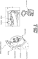
- FIG. 2 is a partial perspective view of a prior art plug assembly.
- the plug assembly includes a housing for a standard plug having male contacts, which supply charge current to complementary female jack contacts on EVs.
- the shown plug and jack are compliant with the J1772 standard, which defines how EVSE connects with, communicates with, and charges EVs.
- the J1772 plug is channeled by a guide inserted into a complementary trough disposed on the J1772 jack, which has a latch for engaging a standard plug latch positioned on the plug housing.
- the plug latch is spring-loaded by a fulcrum at a suitably positioned point where it pivots around a loaded spring.
- the plug latch can be activated by a button to engage and disengage the J1772 plug and jack from each other.
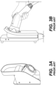
- FIG. 3 A shows one implementation of a prior art EVSE holster with a fixed-type female profile.
- a user docks the standard J1772 plug shown in FIG. 2 by inserting it into the EVSE holster along the line of entry/exit (shown with dotted line).
- the button shown in FIG. 2 must be pressed to engage and disengage the J1172 plug from the EVSE holster.
- FIG. 3 B is a side view of a charger assembly showing a prior art EVSE holster with a swivel-type female holster profile.
- This holster by ChargePoint uses a multipart swivel mechanism with the fixed-type female profile.
- a plug button must be pressed to disengage the plug from this EVSE holster.
- an EVSE holster assembly for docking and undocking an EVSE plug assembly has a plug used to charge an EV via a complementary jack located on the EV and a spring-loaded plug latch that engages to and disengages from a complementary jack.
- the EVSE holster assembly comprises a holster housing that receives the EVSE plug assembly.
- the EVSE plug assembly has a top side and a bottom side where the top side of the holster housing is part of a holster latch partition and the bottom side of the holster housing is part of a plug partition.
- a holster latch is fixed within the latch partition for docking engagement and undocking disengagement with the spring-loaded plug latch based on radial movements of the EVSE plug assembly within the holster housing.
- the bottom side of the plug partition has a concaved portion that provides a path for a curvilinear motion of the EVSE plug assembly within the holster housing.
- An electric vehicle charger for charging a vehicle has a housing.
- a holster is fixedly attached to the housing having a latch partition and a plug partition.
- the plug partition houses a plug latch.
- a plug having a male charging connector is inserted into the hosing, where a spring-loaded latch positioned on a male charging connector engages and disengages the plug latch.
- the plug partition has a curvature that allows the plug to be inserted into the holster at an angle for engaging the spring-loaded latch with the plug latch.
- the spring-loaded latch disengages from the plug latch by a radial movement along the path of the curvature.
- FIG. 1 shows a perspective view of a prior art EVSE.
- FIG. 2 is a partial perspective view of a standard J1772 plug and jack.
- FIG. 3 A is a perspective view of one implementation of a prior art EVSE holster having a fixed-type female profile.
- FIG. 3 B is a perspective view of another implementation of a prior art EVSE holster having a swivel-type female holster profile.
- FIG. 4 A is a perspective view of an EVSE assembly used for charging EVs.
- FIG. 4 B is a side view of the EVSE assembly depicting its orientation lines.
- FIGS. 5 A, 5 B and 5 C are respectively front perspective, left perspective and right perspective views the holster assembly used in the EVSE shown in FIGS. 4 A and 4 B .
- FIG. 6 is a perspective view of a plug assembly docked at an EVSE holster assembly according to the present invention.
- FIG. 7 is a sectional view of FIG. 6 depicting the EVSE holster assembly according to the present invention.
- FIG. 8 A and FIG. 8 B are, respectively, sectional and perspective views depicting curvilinear movement according to the present invention of the J1772 plug in the middle of the EVSE holster housing of the present invention.
- FIG. 9 A and FIG. 9 B are, respectively, sectional and perspective views depicting curvilinear movement according to the present invention of the J1772 plug outside of the EVSE holster housing of the present invention.
- the present invention relates to an EVSE holster used for docking an EV charging plug that provides the ergonomic advantage of self-aligning such plug when it is inserted into the EVSE holster. For example, the user experience is simplified by circumventing the need to press a button to disengage the plug from the EVSE holster.
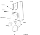
- FIG. 4 A is a perspective view of an EVSE depicting a top side and a bottom side along an axis A-A, which is perpendicular to ground.
- the EVSE manages the link from a power grid or household power to an EV via a cable attached to a plug that is insertable into an EVSE holster when docked and removable from the EVSE holster when undocked.
- a bracket holds the cable when the plug is docked.
- the EVSE can be affixed to a wall for use at home or garage, where an enclosure holds a holster assembly that receives a plug assembly.
- the plug used in the plug assembly complies with the J1772 standard, as shown in FIG. 2 .
- FIG. 4 B is a side view of the EVSE depicting its orientation lines. As shown, the horizontal axis B-B of the EVSE at position parallel to ground is referenced at a 0° degree angle.
- the plug assembly when docked is positioned along an axis C-C, which has a downward 30° angle.
- the plug assembly can radially move to an upward 15° angle along a D-D axis. After undocking, the plug assembly can radially move to be positioned along the C-C axis. In other words, the radial movement range of the plug assembly for docking and undocking is 45°.
- FIGS. 5 A, 5 B and 5 C are respectively front perspective, left perspective and right perspective views the holster assembly used in the EVSE shown in FIGS. 4 A and 4 B .
- the holster assembly includes a housing and a latch disposed within a compartment formed by the housing.
- the holster housing receives the EVSE plug assembly within its compartment.
- the top side of the holster housing is part of a holster latch partition and the bottom side of the holster housing is part of a plug partition.
- the holster latch is fixed within the latch partition for docking engagement and undocking disengagement based on radial movements of the EVSE plug assembly within the holster housing.
- the bottom side of the plug partition has a concaved portion that is hollowed out or rounded inward where the bottom side surfaces “cave” in towards the ground.
- the concaved portion provides a curved path for a curvilinear motion of the EVSE plug assembly within the holster housing.
- FIG. 6 is a perspective view of the plug docked at the EVSE holster shown in FIG. 4 A and FIG. 4 B .
- the EVSE holster is part of the holster assembly shown in FIGS. 5 A- 5 C
- the plug is part of a plug assembly.
- the holster and plug assemblies are made of molded parts, for example, parts made of plastic or any other suitable material having a solid and rigid state.
- the holster is made of ABS plastic and the holster latch is glass-filled nylon.
- the parts used in the holster assembly include the holster housing that holds the holster latch in a fixed place.
- the parts of the plug assembly include a plug housing that houses the J1772 plug shown in FIG. 2 and holds a spring-loaded plug latch within opposing grooves formed on the plug housing.
- the holster housing can, for example, be screwed to the enclosure shown in FIG. 4 via screw holes, thereby fixing the holster compartment shown in FIGS. 5 A- 5 C on the EVSE for inserting or otherwise receiving the J1772 plug.
- the holster latch engages and disengages with the spring-loaded plug latch through forward and backward curvilinear motions as further described below.
- FIG. 7 is a sectional view of FIG. 6 depicting the holster housing being partitioned into a latch partition formed on top of a plug partition.
- the holster latch is secured to a fixed point within the latch partition by a retaining screw and a fixed protruding rail formed on the holster housing, which engages a complementary holding conduit formed on the holster latch, as shown in FIG. 7 .
- Also formed on the holster latch is a channel between a latch-holding conduit and an upwardly protruding edge of the holster latch, which engages a complementary downwardly protruding edge of the spring-loaded plug latch when the plug is docked by insertion into the holster housing.
- the bottom side of the holster housing has a curvature in the form of a downwardly curved portion within the plug partition, which causes plug self-alignment within the holster housing.
- the curved portion allows for forward and backward curvilinear motions of the J1772 plug within the plug partition.
- the J1772 plug is insertable into the holster housing at an angle that engages the spring-loaded plug latch with the holster latch.
- the holster latch channel allows the downwardly protruding edge to move freely back and forth.
- the spring-loaded plug latch disengages from the holster latch by a radial movement along the path of the curvature. This results in a curvilinear motion of the J1772 plug, which moves along a curved path within the plug partition of the holster housing in a self-aligning manner.
- FIG. 8 A and FIG. 8 B are, respectively, sectional and perspective views depicting curvilinear movement, according to the present invention, of the J1772 plug in the middle of the holster housing.
- This depiction assumes the fixed-level position of the EVSE to the ground is at a 0° angle.
- the holster housing is attached to the EVSE in a way that positions the plug partition at a downward angle of 30° towards the ground. This downward angle is the rest angle of the inserted J1772 plug when docked by full engagement of the spring-loaded plug latch with the holster latch, as shown in FIG. 7 .
- FIG. 9 A and FIG. 9 B are, respectively, sectional and perspective views depicting curvilinear movement, according to the present invention, of the J1772 plug outside of the holster housing after it is undocked.
- the radial movement upward reaches the upward 15° angel which completes the J1772 plug's travels along the curved path outside of the plug partition.
- the present invention provides a self-aligning holster solution, which improves user experience during docking and undocking of the J1772 plug.
- the radial upward and downward movements facilitated by the above-described curvature path result in curvilinear motion of the plug in the self-aligning holster, providing a simple and cost-effective solution for circumventing the need to actuate a button to dock or undock the J1772 plug.
Landscapes
- Engineering & Computer Science (AREA)
- Power Engineering (AREA)
- Transportation (AREA)
- Mechanical Engineering (AREA)
- Details Of Connecting Devices For Male And Female Coupling (AREA)
Abstract
Description
Claims (2)
Priority Applications (1)
| Application Number | Priority Date | Filing Date | Title |
|---|---|---|---|
| US17/480,278 US12166313B2 (en) | 2021-09-21 | 2021-09-21 | Self-aligning holster for J1772 plug used in electric vehicle supply equipment |
Applications Claiming Priority (1)
| Application Number | Priority Date | Filing Date | Title |
|---|---|---|---|
| US17/480,278 US12166313B2 (en) | 2021-09-21 | 2021-09-21 | Self-aligning holster for J1772 plug used in electric vehicle supply equipment |
Publications (2)
| Publication Number | Publication Date |
|---|---|
| US20230106493A1 US20230106493A1 (en) | 2023-04-06 |
| US12166313B2 true US12166313B2 (en) | 2024-12-10 |
Family
ID=85774726
Family Applications (1)
| Application Number | Title | Priority Date | Filing Date |
|---|---|---|---|
| US17/480,278 Active 2042-03-23 US12166313B2 (en) | 2021-09-21 | 2021-09-21 | Self-aligning holster for J1772 plug used in electric vehicle supply equipment |
Country Status (1)
| Country | Link |
|---|---|
| US (1) | US12166313B2 (en) |
Families Citing this family (1)
| Publication number | Priority date | Publication date | Assignee | Title |
|---|---|---|---|---|
| DE102021118903A1 (en) * | 2021-07-21 | 2023-01-26 | Huber+Suhner Ag | Axial rotatable connector |
Citations (2)
| Publication number | Priority date | Publication date | Assignee | Title |
|---|---|---|---|---|
| US8025526B1 (en) * | 2010-04-21 | 2011-09-27 | Coulomb Technologies, Inc. | Self powered electric vehicle charging connector locking system |
| US20120091961A1 (en) * | 2010-01-11 | 2012-04-19 | Leviton Manufacturing Co., Inc. | Electric vehicle supply equipment with storage connector |
-
2021
- 2021-09-21 US US17/480,278 patent/US12166313B2/en active Active
Patent Citations (2)
| Publication number | Priority date | Publication date | Assignee | Title |
|---|---|---|---|---|
| US20120091961A1 (en) * | 2010-01-11 | 2012-04-19 | Leviton Manufacturing Co., Inc. | Electric vehicle supply equipment with storage connector |
| US8025526B1 (en) * | 2010-04-21 | 2011-09-27 | Coulomb Technologies, Inc. | Self powered electric vehicle charging connector locking system |
Also Published As
| Publication number | Publication date |
|---|---|
| US20230106493A1 (en) | 2023-04-06 |
Similar Documents
| Publication | Publication Date | Title |
|---|---|---|
| US10299650B2 (en) | Cleaner holder | |
| US6265845B1 (en) | Portable battery charger having a separate battery pack | |
| KR200216672Y1 (en) | Handy chager for cellular phones | |
| US8547059B2 (en) | Lock structure for battery charging connector | |
| US9356454B2 (en) | Apparatus for charging batteries of devices at a selected DC voltage | |
| US9966712B1 (en) | Battery plug-in device for material handling equipment | |
| US20110084660A1 (en) | Wall charger with removable charger | |
| US20190267758A1 (en) | Electricity charging plug device, electricity charging connection device, electricity charging device and electric vehicle | |
| KR20150044381A (en) | Motor vehicle charging inlet structure | |
| US5869947A (en) | Rechargeable hand held vacuum cleaner with electrical connections circuit board with spring contacts | |
| EP0470754A2 (en) | Battery Chargers | |
| US12166313B2 (en) | Self-aligning holster for J1772 plug used in electric vehicle supply equipment | |
| CN213283359U (en) | Cart and portable ultrasound system using the same | |
| US20130149918A1 (en) | Connector | |
| KR20170126378A (en) | Charging device for cleaner | |
| US11864720B2 (en) | Rechargeable battery for powering a vacuum cleaner | |
| KR101841455B1 (en) | Stand for Cleaner | |
| US20140329400A1 (en) | Lock device | |
| KR102010288B1 (en) | Recharging device for electric vehicle | |
| CN217362077U (en) | Multipurpose charging socket | |
| US20150035479A1 (en) | Battery charger | |
| JPH06236775A (en) | Battery-powered appliance holding device | |
| JP5079053B2 (en) | Power supply connector and power supply plug | |
| CN215377618U (en) | Detachable rechargeable battery device and chair thereof | |
| CN210911986U (en) | Battery pack and electric vehicle with same |
Legal Events
| Date | Code | Title | Description |
|---|---|---|---|
| FEPP | Fee payment procedure |
Free format text: ENTITY STATUS SET TO UNDISCOUNTED (ORIGINAL EVENT CODE: BIG.); ENTITY STATUS OF PATENT OWNER: LARGE ENTITY |
|
| AS | Assignment |
Owner name: SEMACONNECT, INC., MARYLAND Free format text: ASSIGNMENT OF ASSIGNORS INTEREST;ASSIGNORS:MOULIK, DYUTIMAN;HEGDE, RAJAT;ALI, GHOUSE;REEL/FRAME:057599/0886 Effective date: 20210924 |
|
| FEPP | Fee payment procedure |
Free format text: ENTITY STATUS SET TO SMALL (ORIGINAL EVENT CODE: SMAL); ENTITY STATUS OF PATENT OWNER: LARGE ENTITY |
|
| STPP | Information on status: patent application and granting procedure in general |
Free format text: DOCKETED NEW CASE - READY FOR EXAMINATION |
|
| STPP | Information on status: patent application and granting procedure in general |
Free format text: NON FINAL ACTION MAILED |
|
| STPP | Information on status: patent application and granting procedure in general |
Free format text: RESPONSE TO NON-FINAL OFFICE ACTION ENTERED AND FORWARDED TO EXAMINER |
|
| STPP | Information on status: patent application and granting procedure in general |
Free format text: FINAL REJECTION MAILED |
|
| STPP | Information on status: patent application and granting procedure in general |
Free format text: RESPONSE AFTER FINAL ACTION FORWARDED TO EXAMINER |
|
| STPP | Information on status: patent application and granting procedure in general |
Free format text: NOTICE OF ALLOWANCE MAILED -- APPLICATION RECEIVED IN OFFICE OF PUBLICATIONS |
|
| AS | Assignment |
Owner name: BLINK SUB II LLC, MARYLAND Free format text: MERGER;ASSIGNOR:SEMMACONNECT INC.;REEL/FRAME:068129/0035 Effective date: 20220615 |
|
| FEPP | Fee payment procedure |
Free format text: ENTITY STATUS SET TO UNDISCOUNTED (ORIGINAL EVENT CODE: BIG.); ENTITY STATUS OF PATENT OWNER: LARGE ENTITY |
|
| STPP | Information on status: patent application and granting procedure in general |
Free format text: PUBLICATIONS -- ISSUE FEE PAYMENT RECEIVED |
|
| STPP | Information on status: patent application and granting procedure in general |
Free format text: PUBLICATIONS -- ISSUE FEE PAYMENT VERIFIED |
|
| STCF | Information on status: patent grant |
Free format text: PATENTED CASE |