US12166310B2 - Electrical connector having insulative housing with a rear platform to secure a sealing member - Google Patents
Electrical connector having insulative housing with a rear platform to secure a sealing member Download PDFInfo
- Publication number
- US12166310B2 US12166310B2 US17/571,700 US202217571700A US12166310B2 US 12166310 B2 US12166310 B2 US 12166310B2 US 202217571700 A US202217571700 A US 202217571700A US 12166310 B2 US12166310 B2 US 12166310B2
- Authority
- US
- United States
- Prior art keywords
- insulative housing
- electrical connector
- outer cover
- sealing member
- chamber
- Prior art date
- Legal status (The legal status is an assumption and is not a legal conclusion. Google has not performed a legal analysis and makes no representation as to the accuracy of the status listed.)
- Active, expires
Links
- 238000007789 sealing Methods 0.000 title claims abstract description 18
- 230000002093 peripheral effect Effects 0.000 claims abstract description 16
- 230000003746 surface roughness Effects 0.000 claims description 3
- 239000000463 material Substances 0.000 claims description 2
- 230000013011 mating Effects 0.000 description 2
- 230000003247 decreasing effect Effects 0.000 description 1
- 230000000694 effects Effects 0.000 description 1
- 230000007613 environmental effect Effects 0.000 description 1
- 239000003292 glue Substances 0.000 description 1
- 229910052751 metal Inorganic materials 0.000 description 1
- 238000005555 metalworking Methods 0.000 description 1
- 238000000034 method Methods 0.000 description 1
- 238000000465 moulding Methods 0.000 description 1
- 238000000926 separation method Methods 0.000 description 1
- 238000005476 soldering Methods 0.000 description 1
Images


Classifications
-
- H—ELECTRICITY
- H01—ELECTRIC ELEMENTS
- H01R—ELECTRICALLY-CONDUCTIVE CONNECTIONS; STRUCTURAL ASSOCIATIONS OF A PLURALITY OF MUTUALLY-INSULATED ELECTRICAL CONNECTING ELEMENTS; COUPLING DEVICES; CURRENT COLLECTORS
- H01R4/00—Electrically-conductive connections between two or more conductive members in direct contact, i.e. touching one another; Means for effecting or maintaining such contact; Electrically-conductive connections having two or more spaced connecting locations for conductors and using contact members penetrating insulation
- H01R4/70—Insulation of connections
-
- H—ELECTRICITY
- H01—ELECTRIC ELEMENTS
- H01R—ELECTRICALLY-CONDUCTIVE CONNECTIONS; STRUCTURAL ASSOCIATIONS OF A PLURALITY OF MUTUALLY-INSULATED ELECTRICAL CONNECTING ELEMENTS; COUPLING DEVICES; CURRENT COLLECTORS
- H01R13/00—Details of coupling devices of the kinds covered by groups H01R12/70 or H01R24/00 - H01R33/00
- H01R13/46—Bases; Cases
- H01R13/52—Dustproof, splashproof, drip-proof, waterproof, or flameproof cases
- H01R13/5219—Sealing means between coupling parts, e.g. interfacial seal
-
- H—ELECTRICITY
- H01—ELECTRIC ELEMENTS
- H01R—ELECTRICALLY-CONDUCTIVE CONNECTIONS; STRUCTURAL ASSOCIATIONS OF A PLURALITY OF MUTUALLY-INSULATED ELECTRICAL CONNECTING ELEMENTS; COUPLING DEVICES; CURRENT COLLECTORS
- H01R13/00—Details of coupling devices of the kinds covered by groups H01R12/70 or H01R24/00 - H01R33/00
- H01R13/46—Bases; Cases
- H01R13/502—Bases; Cases composed of different pieces
-
- H—ELECTRICITY
- H01—ELECTRIC ELEMENTS
- H01R—ELECTRICALLY-CONDUCTIVE CONNECTIONS; STRUCTURAL ASSOCIATIONS OF A PLURALITY OF MUTUALLY-INSULATED ELECTRICAL CONNECTING ELEMENTS; COUPLING DEVICES; CURRENT COLLECTORS
- H01R13/00—Details of coupling devices of the kinds covered by groups H01R12/70 or H01R24/00 - H01R33/00
- H01R13/46—Bases; Cases
- H01R13/516—Means for holding or embracing insulating body, e.g. casing, hoods
-
- H—ELECTRICITY
- H01—ELECTRIC ELEMENTS
- H01R—ELECTRICALLY-CONDUCTIVE CONNECTIONS; STRUCTURAL ASSOCIATIONS OF A PLURALITY OF MUTUALLY-INSULATED ELECTRICAL CONNECTING ELEMENTS; COUPLING DEVICES; CURRENT COLLECTORS
- H01R12/00—Structural associations of a plurality of mutually-insulated electrical connecting elements, specially adapted for printed circuits, e.g. printed circuit boards [PCB], flat or ribbon cables, or like generally planar structures, e.g. terminal strips, terminal blocks; Coupling devices specially adapted for printed circuits, flat or ribbon cables, or like generally planar structures; Terminals specially adapted for contact with, or insertion into, printed circuits, flat or ribbon cables, or like generally planar structures
- H01R12/70—Coupling devices
- H01R12/71—Coupling devices for rigid printing circuits or like structures
- H01R12/72—Coupling devices for rigid printing circuits or like structures coupling with the edge of the rigid printed circuits or like structures
- H01R12/722—Coupling devices for rigid printing circuits or like structures coupling with the edge of the rigid printed circuits or like structures coupling devices mounted on the edge of the printed circuits
-
- H—ELECTRICITY
- H01—ELECTRIC ELEMENTS
- H01R—ELECTRICALLY-CONDUCTIVE CONNECTIONS; STRUCTURAL ASSOCIATIONS OF A PLURALITY OF MUTUALLY-INSULATED ELECTRICAL CONNECTING ELEMENTS; COUPLING DEVICES; CURRENT COLLECTORS
- H01R13/00—Details of coupling devices of the kinds covered by groups H01R12/70 or H01R24/00 - H01R33/00
- H01R13/46—Bases; Cases
- H01R13/52—Dustproof, splashproof, drip-proof, waterproof, or flameproof cases
- H01R13/521—Sealing between contact members and housing, e.g. sealing insert
-
- H—ELECTRICITY
- H01—ELECTRIC ELEMENTS
- H01R—ELECTRICALLY-CONDUCTIVE CONNECTIONS; STRUCTURAL ASSOCIATIONS OF A PLURALITY OF MUTUALLY-INSULATED ELECTRICAL CONNECTING ELEMENTS; COUPLING DEVICES; CURRENT COLLECTORS
- H01R24/00—Two-part coupling devices, or either of their cooperating parts, characterised by their overall structure
- H01R24/60—Contacts spaced along planar side wall transverse to longitudinal axis of engagement
Definitions
- the present invention relates to electrical connector comprising an insulative housing, an outer cover enclosing the insulative housing to define a front chamber and a rear chamber, and a plurality of contacts secured to the insulative housing, exposed to the front chamber, and extending through the rear chamber, and a sealing member formed in the rear chamber to seal an interface between the insulative housing and the outer cover, wherein the insulative housing is designed to firmly secure the sealing member in place.
- China Patent No. 107293894 discloses an electrical connector comprising an insulative housing, an outer cover structure enclosing the insulative housing, a plurality of contacts secured to the insulative housing, and a rear sealing member to seal an interface between the insulative housing and the outer cover structure. Under environmental tests adhesion of the sealing member to the insulative housing and/or the outer cover structure may become deteriorated such that gas tight sealing effect is decreased.
- An electrical connector comprises: an insulative housing having a base and a rear platform; an outer cover enclosing the insulative housing to define a front chamber and a rear chamber; a plurality of contacts secured to the insulative housing, exposed to the front chamber, and extending through the rear chamber; and a sealing member formed in the rear chamber to seal an interface between the insulative housing and the outer cover, wherein the rear platform has a peripheral face spaced a gap from the outer cover and the peripheral face has a roughened surface.
- FIG. 1 is a perspective view of an electrical connector in accordance with the present invention
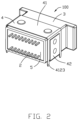
- FIG. 2 is another perspective view of the electrical connector
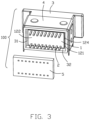
- FIG. 3 is a partially exploded view of the electrical connector in FIG. 2 ;
- FIG. 4 is a cross-sectional view of the electrical connector taken along line A-A in FIG. 1 ;
- FIG. 5 is an exploded view of the electrical connector in FIG. 1 ;
- FIG. 6 another exploded view of the electrical connector in FIG. 1 .
- an electrical connector 100 comprises an insulative housing 1 , an outer cover 3 enclosing the insulative housing 1 to define a front mating chamber 30 and a rear filling chamber 31 , a plurality of contacts 2 secured to the insulative housing 1 , exposed to the front chamber 30 , and extending through the rear chamber 31 , and a sealing member 5 formed in the rear chamber to seal an interface between the insulative housing 1 and the outer cover 3 .
- the electrical connector 100 may further include a fixing element 4 fastened to the outer cover 3 .
- the insulative housing 1 includes a base 11 and a platform 12 protruding rearward from the base 11 .
- the base 11 has a front face 111 , a rear face 112 , and a peripheral face 113 .
- the base 11 is substantially parallelpiped, though it may well be of other shapes.
- the peripheral face 113 includes a top face 1131 and a bottom face 1133 and a pair of side faces 1132 and 1134 .
- the peripheral face 113 abuts an inner wall face 32 of the outer cover 3 .
- the platform 12 is also substantially parallelpiped, though it may be of other shapes, so that a peripheral face 121 thereof is spaced a gap 124 all way around from the inner wall face 32 of the outer cover 3 .
- the peripheral face 121 has a roughened surface with a surface roughness Ra greater than that of the peripheral face 113 of the base 11 .
- the platform 12 has a rear face 122 and a rounded or chamfered face 123 at a junction of the rear face 122 and the peripheral face 121 .
- a step 125 is defined at the rear face 112 of the base 11 .
- the peripheral face 121 includes faces 1211 , 1213 , 1212 , and 12124 corresponding to the top and bottom face 1131 and 1133 and the pair of side faces 1132 and 1134 , respectively.
- the chamfered face 123 ameliorates separation of the sealing member 5 from the insulative housing 1 due to different thermal coefficients of expansion thereof.
- the surface roughness Ra of the peripheral face 121 is greater than 3.15 micrometer to obtain a stronger bond with the sealing member 5 when cured in place. Therefore, even if adhesion of the sealing member to the insulative housing and/or the outer cover were deteriorated, the sealing member 5 is still securely kept in place to perform its intended function.
- the rear face 122 of the platform 12 may also be roughened for further assisting in keeping the sealing member 5 in place.
- the step 125 may also be roughened. The roughened face may be produced by suitable metalworking process on associated molding tools.
- the outer cover 3 includes the front chamber 30 and a rear chamber 36 .
- the rear chamber 36 has a receiving part 361 accommodating the insulative housing 1 and the filling chamber 31 .
- the outer cover 3 has an inner wall 32 includes walls 321 , 322 , 323 , and 324 corresponding to the top and bottom face 1131 and 1133 and the pair of side faces 1132 and 1134 , respectively.
- the outer cover 3 is made of plastic material in this embodiment, though it may also be a metallic element.
- the outer cover 3 has a dividing wall 33 . Slots 34 are formed on the dividing wall 33 and the walls 321 and 322 for accommodating the terminals 2 .
- the wall 321 further has a pair of posts 35 for fastening the fixing element 4 .
- the sealing member 5 e.g., glues cured in the filling chamber 31 , is firmly secured in place, especially adhering to the peripheral face 121 of the platform 12 , and to the rear face 122 of the platform 12 and the step 125 of the base 11 if roughened.
- the terminals 2 are arranged in two rows and each terminal includes a contacting portion 21 , a soldering portion 23 , and a connecting portion 22 .
- the connecting portion 22 is secured in the insulative housing 1 and the contacting portion 21 protrudes into the front mating chamber 30 .
- the fixing element 4 includes an upper piece 41 and a lower piece 42 .
- the upper piece 41 has a top plate 411 and a pair of side plates 412 .
- the top plate 411 has a pair of holes 4111 for receiving the pair of posts 35 .
- Each side plate 412 has a bottom edge 4122 and a pair of legs 4123 .
- the lower piece 42 has a bottom plate 421 and a pair of side plates 422 .
- the lower piece 42 is spot welded to the upper piece 41 at several positions 4121 .
Landscapes
- Connector Housings Or Holding Contact Members (AREA)
- Details Of Connecting Devices For Male And Female Coupling (AREA)
Abstract
Description
Claims (6)
Applications Claiming Priority (2)
| Application Number | Priority Date | Filing Date | Title |
|---|---|---|---|
| CN202120208478.9 | 2021-01-26 | ||
| CN202120208478.9U CN214254865U (en) | 2021-01-26 | 2021-01-26 | Electrical connector |
Publications (2)
| Publication Number | Publication Date |
|---|---|
| US20220239034A1 US20220239034A1 (en) | 2022-07-28 |
| US12166310B2 true US12166310B2 (en) | 2024-12-10 |
Family
ID=77794684
Family Applications (1)
| Application Number | Title | Priority Date | Filing Date |
|---|---|---|---|
| US17/571,700 Active 2043-01-15 US12166310B2 (en) | 2021-01-26 | 2022-01-10 | Electrical connector having insulative housing with a rear platform to secure a sealing member |
Country Status (3)
| Country | Link |
|---|---|
| US (1) | US12166310B2 (en) |
| CN (1) | CN214254865U (en) |
| TW (1) | TWM633915U (en) |
Families Citing this family (1)
| Publication number | Priority date | Publication date | Assignee | Title |
|---|---|---|---|---|
| DE102022114167B3 (en) * | 2022-06-03 | 2023-09-28 | Doubleeagle Industry (China) Limited | Electrical socket for a construction toy |
Citations (4)
| Publication number | Priority date | Publication date | Assignee | Title |
|---|---|---|---|---|
| US7871288B1 (en) * | 2009-12-16 | 2011-01-18 | Longwell Company | Power connector structure |
| US9437957B2 (en) * | 2014-12-05 | 2016-09-06 | Simula Technology Inc. | Waterproof connector having internally concealed grounding pin |
| CN205752769U (en) | 2016-07-01 | 2016-11-30 | 上海莫仕连接器有限公司 | Electric connector |
| CN107293894A (en) | 2016-04-01 | 2017-10-24 | 富士康(昆山)电脑接插件有限公司 | Electric connector and its manufacture method |
-
2021
- 2021-01-26 CN CN202120208478.9U patent/CN214254865U/en active Active
-
2022
- 2022-01-10 US US17/571,700 patent/US12166310B2/en active Active
- 2022-01-14 TW TW111200521U patent/TWM633915U/en unknown
Patent Citations (4)
| Publication number | Priority date | Publication date | Assignee | Title |
|---|---|---|---|---|
| US7871288B1 (en) * | 2009-12-16 | 2011-01-18 | Longwell Company | Power connector structure |
| US9437957B2 (en) * | 2014-12-05 | 2016-09-06 | Simula Technology Inc. | Waterproof connector having internally concealed grounding pin |
| CN107293894A (en) | 2016-04-01 | 2017-10-24 | 富士康(昆山)电脑接插件有限公司 | Electric connector and its manufacture method |
| CN205752769U (en) | 2016-07-01 | 2016-11-30 | 上海莫仕连接器有限公司 | Electric connector |
Also Published As
| Publication number | Publication date |
|---|---|
| CN214254865U (en) | 2021-09-21 |
| US20220239034A1 (en) | 2022-07-28 |
| TWM633915U (en) | 2022-11-11 |
Similar Documents
| Publication | Publication Date | Title |
|---|---|---|
| KR101702877B1 (en) | Waterproof connector | |
| US6219913B1 (en) | Connector producing method and a connector produced by insert molding | |
| US9768560B2 (en) | Electrical connector having improved shielding shell | |
| US9331414B2 (en) | Electrical connector | |
| US9997859B2 (en) | Electrical connector having a firmly secured front sealing member | |
| CN104112929B (en) | Electronic building brick and its manufacture method | |
| JP6418324B2 (en) | Multi-pole connector | |
| KR101688025B1 (en) | Waterproof connector | |
| JP7163615B2 (en) | power storage device | |
| CN113228424A (en) | Socket connector | |
| KR20170130282A (en) | Electrical connector and production method thereof | |
| US20180213658A1 (en) | Electronic apparatus unit | |
| US12237621B2 (en) | Electrical connector having a middle grounding member abutted by outermost ground contacts of first and second rows of contacts | |
| CN101507375A (en) | Compliant pin control module and method of manufacturing the same | |
| US9570836B2 (en) | Connector, electrical connection box and connector manufacturing method | |
| TW201904141A (en) | Electrical connector | |
| US10205254B2 (en) | Electrical connector and method of making the same | |
| US9545001B2 (en) | Printed board with board terminal and electrical connection box using same | |
| US12166310B2 (en) | Electrical connector having insulative housing with a rear platform to secure a sealing member | |
| CN104103940B (en) | Straight-through mainboard socket and manufacture method thereof | |
| CN209948178U (en) | Radio frequency switch connector | |
| US20220200195A1 (en) | Connector | |
| CN102437471A (en) | Connector | |
| EP2176925A1 (en) | Electrical connector for use in soldering operations | |
| JP5112504B2 (en) | Manufacturing method of shielded connector |
Legal Events
| Date | Code | Title | Description |
|---|---|---|---|
| AS | Assignment |
Owner name: FOXCONN INTERCONNECT TECHNOLOGY LIMITED, CAYMAN ISLANDS Free format text: ASSIGNMENT OF ASSIGNORS INTEREST;ASSIGNORS:KO, TE-NENG;TING, CHIEN-JEN;REEL/FRAME:058591/0810 Effective date: 20211209 Owner name: FOXCONN (KUNSHAN) COMPUTER CONNECTOR CO., LTD., CHINA Free format text: ASSIGNMENT OF ASSIGNORS INTEREST;ASSIGNORS:KO, TE-NENG;TING, CHIEN-JEN;REEL/FRAME:058591/0810 Effective date: 20211209 |
|
| FEPP | Fee payment procedure |
Free format text: ENTITY STATUS SET TO UNDISCOUNTED (ORIGINAL EVENT CODE: BIG.); ENTITY STATUS OF PATENT OWNER: LARGE ENTITY |
|
| STPP | Information on status: patent application and granting procedure in general |
Free format text: DOCKETED NEW CASE - READY FOR EXAMINATION |
|
| STPP | Information on status: patent application and granting procedure in general |
Free format text: NON FINAL ACTION MAILED |
|
| STPP | Information on status: patent application and granting procedure in general |
Free format text: RESPONSE TO NON-FINAL OFFICE ACTION ENTERED AND FORWARDED TO EXAMINER |
|
| STPP | Information on status: patent application and granting procedure in general |
Free format text: NOTICE OF ALLOWANCE MAILED -- APPLICATION RECEIVED IN OFFICE OF PUBLICATIONS |
|
| STCF | Information on status: patent grant |
Free format text: PATENTED CASE |