US12157724B2 - Compound and organic light emitting device comprising the same - Google Patents
Compound and organic light emitting device comprising the same Download PDFInfo
- Publication number
- US12157724B2 US12157724B2 US17/050,328 US201917050328A US12157724B2 US 12157724 B2 US12157724 B2 US 12157724B2 US 201917050328 A US201917050328 A US 201917050328A US 12157724 B2 US12157724 B2 US 12157724B2
- Authority
- US
- United States
- Prior art keywords
- compound
- group
- light emitting
- substituted
- unsubstituted
- Prior art date
- Legal status (The legal status is an assumption and is not a legal conclusion. Google has not performed a legal analysis and makes no representation as to the accuracy of the status listed.)
- Active, expires
Links
Images


Classifications
-
- C—CHEMISTRY; METALLURGY
- C07—ORGANIC CHEMISTRY
- C07D—HETEROCYCLIC COMPOUNDS
- C07D333/00—Heterocyclic compounds containing five-membered rings having one sulfur atom as the only ring hetero atom
- C07D333/50—Heterocyclic compounds containing five-membered rings having one sulfur atom as the only ring hetero atom condensed with carbocyclic rings or ring systems
- C07D333/52—Benzo[b]thiophenes; Hydrogenated benzo[b]thiophenes
- C07D333/54—Benzo[b]thiophenes; Hydrogenated benzo[b]thiophenes with only hydrogen atoms, hydrocarbon or substituted hydrocarbon radicals, directly attached to carbon atoms of the hetero ring
-
- C—CHEMISTRY; METALLURGY
- C07—ORGANIC CHEMISTRY
- C07C—ACYCLIC OR CARBOCYCLIC COMPOUNDS
- C07C211/00—Compounds containing amino groups bound to a carbon skeleton
- C07C211/43—Compounds containing amino groups bound to a carbon skeleton having amino groups bound to carbon atoms of six-membered aromatic rings of the carbon skeleton
- C07C211/57—Compounds containing amino groups bound to a carbon skeleton having amino groups bound to carbon atoms of six-membered aromatic rings of the carbon skeleton having amino groups bound to carbon atoms of six-membered aromatic rings being part of condensed ring systems of the carbon skeleton
- C07C211/61—Compounds containing amino groups bound to a carbon skeleton having amino groups bound to carbon atoms of six-membered aromatic rings of the carbon skeleton having amino groups bound to carbon atoms of six-membered aromatic rings being part of condensed ring systems of the carbon skeleton with at least one of the condensed ring systems formed by three or more rings
-
- C—CHEMISTRY; METALLURGY
- C07—ORGANIC CHEMISTRY
- C07D—HETEROCYCLIC COMPOUNDS
- C07D209/00—Heterocyclic compounds containing five-membered rings, condensed with other rings, with one nitrogen atom as the only ring hetero atom
- C07D209/56—Ring systems containing three or more rings
- C07D209/80—[b, c]- or [b, d]-condensed
- C07D209/82—Carbazoles; Hydrogenated carbazoles
- C07D209/86—Carbazoles; Hydrogenated carbazoles with only hydrogen atoms, hydrocarbon or substituted hydrocarbon radicals, directly attached to carbon atoms of the ring system
-
- C—CHEMISTRY; METALLURGY
- C07—ORGANIC CHEMISTRY
- C07D—HETEROCYCLIC COMPOUNDS
- C07D307/00—Heterocyclic compounds containing five-membered rings having one oxygen atom as the only ring hetero atom
- C07D307/77—Heterocyclic compounds containing five-membered rings having one oxygen atom as the only ring hetero atom ortho- or peri-condensed with carbocyclic rings or ring systems
- C07D307/78—Benzo [b] furans; Hydrogenated benzo [b] furans
- C07D307/79—Benzo [b] furans; Hydrogenated benzo [b] furans with only hydrogen atoms, hydrocarbon or substituted hydrocarbon radicals, directly attached to carbon atoms of the hetero ring
-
- C—CHEMISTRY; METALLURGY
- C07—ORGANIC CHEMISTRY
- C07F—ACYCLIC, CARBOCYCLIC OR HETEROCYCLIC COMPOUNDS CONTAINING ELEMENTS OTHER THAN CARBON, HYDROGEN, HALOGEN, OXYGEN, NITROGEN, SULFUR, SELENIUM OR TELLURIUM
- C07F7/00—Compounds containing elements of Groups 4 or 14 of the Periodic Table
- C07F7/02—Silicon compounds
- C07F7/08—Compounds having one or more C—Si linkages
- C07F7/0803—Compounds with Si-C or Si-Si linkages
- C07F7/081—Compounds with Si-C or Si-Si linkages comprising at least one atom selected from the elements N, O, halogen, S, Se or Te
-
- C—CHEMISTRY; METALLURGY
- C09—DYES; PAINTS; POLISHES; NATURAL RESINS; ADHESIVES; COMPOSITIONS NOT OTHERWISE PROVIDED FOR; APPLICATIONS OF MATERIALS NOT OTHERWISE PROVIDED FOR
- C09K—MATERIALS FOR MISCELLANEOUS APPLICATIONS, NOT PROVIDED FOR ELSEWHERE
- C09K11/00—Luminescent materials, e.g. electroluminescent or chemiluminescent
- C09K11/06—Luminescent materials, e.g. electroluminescent or chemiluminescent containing organic luminescent materials
-
- H—ELECTRICITY
- H10—SEMICONDUCTOR DEVICES; ELECTRIC SOLID-STATE DEVICES NOT OTHERWISE PROVIDED FOR
- H10K—ORGANIC ELECTRIC SOLID-STATE DEVICES
- H10K85/00—Organic materials used in the body or electrodes of devices covered by this subclass
- H10K85/60—Organic compounds having low molecular weight
- H10K85/631—Amine compounds having at least two aryl rest on at least one amine-nitrogen atom, e.g. triphenylamine
- H10K85/633—Amine compounds having at least two aryl rest on at least one amine-nitrogen atom, e.g. triphenylamine comprising polycyclic condensed aromatic hydrocarbons as substituents on the nitrogen atom
-
- H—ELECTRICITY
- H10—SEMICONDUCTOR DEVICES; ELECTRIC SOLID-STATE DEVICES NOT OTHERWISE PROVIDED FOR
- H10K—ORGANIC ELECTRIC SOLID-STATE DEVICES
- H10K85/00—Organic materials used in the body or electrodes of devices covered by this subclass
- H10K85/60—Organic compounds having low molecular weight
- H10K85/631—Amine compounds having at least two aryl rest on at least one amine-nitrogen atom, e.g. triphenylamine
- H10K85/636—Amine compounds having at least two aryl rest on at least one amine-nitrogen atom, e.g. triphenylamine comprising heteroaromatic hydrocarbons as substituents on the nitrogen atom
-
- H—ELECTRICITY
- H10—SEMICONDUCTOR DEVICES; ELECTRIC SOLID-STATE DEVICES NOT OTHERWISE PROVIDED FOR
- H10K—ORGANIC ELECTRIC SOLID-STATE DEVICES
- H10K85/00—Organic materials used in the body or electrodes of devices covered by this subclass
- H10K85/60—Organic compounds having low molecular weight
- H10K85/649—Aromatic compounds comprising a hetero atom
- H10K85/657—Polycyclic condensed heteroaromatic hydrocarbons
- H10K85/6572—Polycyclic condensed heteroaromatic hydrocarbons comprising only nitrogen in the heteroaromatic polycondensed ring system, e.g. phenanthroline or carbazole
-
- H—ELECTRICITY
- H10—SEMICONDUCTOR DEVICES; ELECTRIC SOLID-STATE DEVICES NOT OTHERWISE PROVIDED FOR
- H10K—ORGANIC ELECTRIC SOLID-STATE DEVICES
- H10K85/00—Organic materials used in the body or electrodes of devices covered by this subclass
- H10K85/60—Organic compounds having low molecular weight
- H10K85/649—Aromatic compounds comprising a hetero atom
- H10K85/657—Polycyclic condensed heteroaromatic hydrocarbons
- H10K85/6574—Polycyclic condensed heteroaromatic hydrocarbons comprising only oxygen in the heteroaromatic polycondensed ring system, e.g. cumarine dyes
-
- H—ELECTRICITY
- H10—SEMICONDUCTOR DEVICES; ELECTRIC SOLID-STATE DEVICES NOT OTHERWISE PROVIDED FOR
- H10K—ORGANIC ELECTRIC SOLID-STATE DEVICES
- H10K85/00—Organic materials used in the body or electrodes of devices covered by this subclass
- H10K85/60—Organic compounds having low molecular weight
- H10K85/649—Aromatic compounds comprising a hetero atom
- H10K85/657—Polycyclic condensed heteroaromatic hydrocarbons
- H10K85/6576—Polycyclic condensed heteroaromatic hydrocarbons comprising only sulfur in the heteroaromatic polycondensed ring system, e.g. benzothiophene
-
- C—CHEMISTRY; METALLURGY
- C07—ORGANIC CHEMISTRY
- C07C—ACYCLIC OR CARBOCYCLIC COMPOUNDS
- C07C2603/00—Systems containing at least three condensed rings
- C07C2603/02—Ortho- or ortho- and peri-condensed systems
- C07C2603/04—Ortho- or ortho- and peri-condensed systems containing three rings
- C07C2603/06—Ortho- or ortho- and peri-condensed systems containing three rings containing at least one ring with less than six ring members
- C07C2603/10—Ortho- or ortho- and peri-condensed systems containing three rings containing at least one ring with less than six ring members containing five-membered rings
- C07C2603/12—Ortho- or ortho- and peri-condensed systems containing three rings containing at least one ring with less than six ring members containing five-membered rings only one five-membered ring
- C07C2603/18—Fluorenes; Hydrogenated fluorenes
-
- C—CHEMISTRY; METALLURGY
- C07—ORGANIC CHEMISTRY
- C07C—ACYCLIC OR CARBOCYCLIC COMPOUNDS
- C07C2603/00—Systems containing at least three condensed rings
- C07C2603/56—Ring systems containing bridged rings
- C07C2603/58—Ring systems containing bridged rings containing three rings
- C07C2603/70—Ring systems containing bridged rings containing three rings containing only six-membered rings
- C07C2603/74—Adamantanes
-
- C—CHEMISTRY; METALLURGY
- C07—ORGANIC CHEMISTRY
- C07C—ACYCLIC OR CARBOCYCLIC COMPOUNDS
- C07C2603/00—Systems containing at least three condensed rings
- C07C2603/93—Spiro compounds
- C07C2603/94—Spiro compounds containing "free" spiro atoms
-
- C—CHEMISTRY; METALLURGY
- C09—DYES; PAINTS; POLISHES; NATURAL RESINS; ADHESIVES; COMPOSITIONS NOT OTHERWISE PROVIDED FOR; APPLICATIONS OF MATERIALS NOT OTHERWISE PROVIDED FOR
- C09K—MATERIALS FOR MISCELLANEOUS APPLICATIONS, NOT PROVIDED FOR ELSEWHERE
- C09K2211/00—Chemical nature of organic luminescent or tenebrescent compounds
- C09K2211/10—Non-macromolecular compounds
- C09K2211/1003—Carbocyclic compounds
- C09K2211/1011—Condensed systems
-
- C—CHEMISTRY; METALLURGY
- C09—DYES; PAINTS; POLISHES; NATURAL RESINS; ADHESIVES; COMPOSITIONS NOT OTHERWISE PROVIDED FOR; APPLICATIONS OF MATERIALS NOT OTHERWISE PROVIDED FOR
- C09K—MATERIALS FOR MISCELLANEOUS APPLICATIONS, NOT PROVIDED FOR ELSEWHERE
- C09K2211/00—Chemical nature of organic luminescent or tenebrescent compounds
- C09K2211/10—Non-macromolecular compounds
- C09K2211/1003—Carbocyclic compounds
- C09K2211/1014—Carbocyclic compounds bridged by heteroatoms, e.g. N, P, Si or B
-
- C—CHEMISTRY; METALLURGY
- C09—DYES; PAINTS; POLISHES; NATURAL RESINS; ADHESIVES; COMPOSITIONS NOT OTHERWISE PROVIDED FOR; APPLICATIONS OF MATERIALS NOT OTHERWISE PROVIDED FOR
- C09K—MATERIALS FOR MISCELLANEOUS APPLICATIONS, NOT PROVIDED FOR ELSEWHERE
- C09K2211/00—Chemical nature of organic luminescent or tenebrescent compounds
- C09K2211/10—Non-macromolecular compounds
- C09K2211/1018—Heterocyclic compounds
- C09K2211/1022—Heterocyclic compounds bridged by heteroatoms, e.g. N, P, Si or B
-
- H—ELECTRICITY
- H10—SEMICONDUCTOR DEVICES; ELECTRIC SOLID-STATE DEVICES NOT OTHERWISE PROVIDED FOR
- H10K—ORGANIC ELECTRIC SOLID-STATE DEVICES
- H10K50/00—Organic light-emitting devices
- H10K50/10—OLEDs or polymer light-emitting diodes [PLED]
-
- H—ELECTRICITY
- H10—SEMICONDUCTOR DEVICES; ELECTRIC SOLID-STATE DEVICES NOT OTHERWISE PROVIDED FOR
- H10K—ORGANIC ELECTRIC SOLID-STATE DEVICES
- H10K50/00—Organic light-emitting devices
- H10K50/10—OLEDs or polymer light-emitting diodes [PLED]
- H10K50/14—Carrier transporting layers
- H10K50/15—Hole transporting layers
Definitions
- the present disclosure relates to a novel compound and an organic light emitting device comprising the same.
- an organic light emitting phenomenon refers to a phenomenon where electric energy is converted into light energy by using an organic material.
- the organic light emitting device using the organic light emitting phenomenon has characteristics such as a wide viewing angle, an excellent contrast, a fast response time, an excellent luminance, driving voltage and response speed, and thus many studies have proceeded.
- the organic light emitting device generally has a structure which comprises an anode, a cathode, and an organic material layer interposed between the anode and the cathode.
- the organic material layer frequently has a multilayered structure that comprises different materials in order to enhance efficiency and stability of the organic light emitting device, and for example, the organic material layer may be formed of a hole injection layer, a hole transport layer, a light emitting layer, an electron transport layer, an electron injection layer and the like.
- the holes are injected from an anode into the organic material layer and the electrons are injected from the cathode into the organic material layer, and when the injected holes and electrons meet each other, an exciton is formed, and light is emitted when the exciton falls to a ground state again.
- Patent Literature 0001 Korean Unexamined Patent Publication No. 10-2000-0051826
- an organic light emitting device comprising: a first electrode; a second electrode that is provided opposite to the first electrode; and one or more organic material layers that are provided between the first electrode and the second electrode, wherein one or more layers of the organic material layers include the above-mentioned compound of Chemical Formula 1.
- the above-mentioned compound of Chemical Formula 1 can be used as a material of an organic material layer of an organic light emitting device, and can improve the efficiency, achieve low driving voltage and/or improve lifetime characteristics in the organic light emitting device.
- the compound of Chemical Formula 1 may be used as a hole injection material, hole transport material, hole injection and transport material, light emitting material, electron transport material, or electron injection material.
- FIG. 1 shows an example of an organic light emitting device comprising a substrate 1 , an anode 2 , a light emitting layer 3 , and a cathode 4 .
- FIG. 2 shows an example of an organic light emitting device comprising a substrate 1 , an anode 2 , a hole injection layer 5 , a hole transport layer 6 , a light emitting layer 7 , an electron transport layer 8 , and a cathode 4 .
- the present disclosure provides the compound of Chemical Formula 1.
- substituted or unsubstituted means being unsubstituted or substituted with one or more substituents selected from the group consisting of deuterium; a halogen group; a nitrile group; a nitro group; a hydroxy group; a carbonyl group; an ester group; an imide group; an amino group; a phosphine oxide group; an alkoxy group; an aryloxy group; an alkylthioxy group; an arylthioxy group; an alkylsulfoxy group; an arylsulfoxy group; a silyl group; a boron group; an alkyl group; a cycloalkyl group; an alkenyl group; an aryl group; an aralkyl group; an aralkenyl group; an alkylaryl group; an alkylamine group; an aralkylamine group; a heteroarylamine group; an arylamine group;
- a substituent in which two or more substituents are connected may be a biphenyl group.
- a biphenyl group may be an aryl group, or it may also be interpreted as a substituent in which two phenyl groups are connected.
- the carbon number of a carbonyl group is not particularly limited, but is preferably 1 to 40.
- the carbonyl group may be a compound having the following structural formulas, but is not limited thereto.
- an ester group may have a structure in which oxygen of the ester group may be substituted by a straight-chain, branched-chain, or cyclic alkyl group having 1 to 25 carbon atoms, or an aryl group having 6 to 25 carbon atoms.
- the ester group may be a compound having the following structural formulas, but is not limited thereto.
- the carbon number of an imide group is not particularly limited, but is preferably 1 to 25.
- the imide group may be a compound having the following structural formulas, but is not limited thereto.
- a silyl group specifically includes a trimethylsilyl group, a triethylsilyl group, a t-butyldimethylsilyl group, a vinyldimethylsilyl group, a propyldimethylsilyl group, a triphenylsilyl group, a diphenylsilyl group, a phenylsilyl group and the like, but is not limited thereto.
- a boron group specifically includes a trimethylboron group, a triethylboron group, a t-butyldimethylboron group, a triphenylboron group, and a phenylboron group, but is not limited thereto.
- examples of a halogen group include fluorine, chlorine, bromine, or iodine.
- the alkyl group may be straight-chain or branched-chain, and the carbon number thereof is not particularly limited, but is preferably 1 to 40. According to one embodiment, the carbon number of the alkyl group is 1 to 20. According to another embodiment, the carbon number of the alkyl group is 1 to 10. According to another embodiment, the carbon number of the alkyl group is 1 to 6.
- alkyl group examples include methyl, ethyl, propyl, n-propyl, isopropyl, butyl, n-butyl, isobutyl, tert-butyl, sec-butyl, 1-methyl-butyl, 1-ethyl-butyl, pentyl, n-pentyl, isopentyl, neopentyl, tert-pentyl, hexyl, n-hexyl, 1-methylpentyl, 2-methylpentyl, 4-methyl-2-pentyl, 3,3-dimethylbutyl, 2-ethylbutyl, heptyl, n-heptyl, 1-methylhexyl, cyclopentylmethyl, cyclohexylmethyl, octyl, n-octyl, tert-octyl, 1-methylheptyl, 2-ethylhexyl, 2-
- the alkenyl group may be straight-chain or branched-chain, and the carbon number thereof is not particularly limited, but is preferably 2 to 40. According to one embodiment, the carbon number of the alkenyl group is 2 to 20. According to another embodiment, the carbon number of the alkenyl group is 2 to 10. According to still another embodiment, the carbon number of the alkenyl group is 2 to 6.
- Specific examples thereof include vinyl, 1-propenyl, isopropenyl, 1-butenyl, 2-butenyl, 3-butenyl, 1-pentenyl, 2-pentenyl, 3-pentenyl, 3-methyl-1-butenyl, 1,3-butadienyl, allyl, 1-phenylvinyl-1-yl, 2-phenylvinyl-1-yl, 2,2-diphenylvinyl-1-yl, 2-phenyl-2-(naphthyl-1-yl)vinyl-1-yl, 2,2-bis(diphenyl-1-yl)vinyl-1-yl, a stilbenyl group, a styrenyl group, and the like, but are not limited thereto.
- a cycloalkyl group is not particularly limited, but the carbon number thereof is preferably 3 to 60. According to one embodiment, the carbon number of the cycloalkyl group is 3 to 30. According to another embodiment, the carbon number of the cycloalkyl group is 3 to 20. According to still another embodiment, the carbon number of the cycloalkyl group is 3 to 6.
- cyclopropyl examples thereof include cyclopropyl, cyclobutyl, cyclopentyl, 3-methylcyclopentyl, 2,3-dimethylcyclopentyl, cyclohexyl, 3-methylcyclohexyl, 4-methylcyclohexyl, 2,3-dimethylcyclohexyl, 3,4,5-trimethylcyclohexyl, 4-tert-butylcyclohexyl, cycloheptyl, cyclooctyl, and the like, but are not limited thereto.
- an aryl group is not particularly limited, but the carbon number thereof is preferably 6 to 60, and it may be a monocyclic aryl group or a polycyclic aryl group. According to one embodiment, the carbon number of the aryl group is 6 to 30. According to one embodiment, the carbon number of the aryl group is 6 to 20.
- the aryl group may be a phenyl group, a biphenyl group, a terphenyl group or the like as the monocyclic aryl group, but is not limited thereto.
- the polycyclic aryl group includes a naphthyl group, an anthracenyl group, a phenanthryl group, a pyrenyl group, a perylenyl group, a chrysenyl group, or the like, but is not limited thereto.
- the fluorenyl group may be substituted, and two substituents may be linked with each other to form a Spiro structure.
- the fluorenyl group is substituted,
- a heterocyclic group is a heterocyclic group containing one or more of O, N, Si and S as a heteroatom, and the carbon number thereof is not particularly limited, but is preferably 2 to 60.
- the heterocyclic group include a thiophene group, a furan group, a pyrrole group, an imidazole group, a thiazole group, an oxazol group, an oxadiazol group, a triazol group, a pyridyl group, a bipyridyl group, a pyrimidyl group, a triazine group, an acridyl group, a pyridazine group, a pyrazinyl group, a quinolinyl group, a quinazoline group, a quinoxalinyl group, a phthalazinyl group, a pyridopyrimidinyl group, a pyridopyrazinyl
- the aryl group in the aralkyl group, the aralkenyl group, the alkylaryl group and the arylamine group is the same as the aforementioned examples of the aryl group.
- the alkyl group in the aralkyl group, the alkylaryl group and the alkylamine group is the same as the aforementioned examples of the alkyl group.
- the heteroaryl in the heteroarylamine can be applied to the aforementioned description of the heterocyclic group.
- the alkenyl group in the aralkenyl group is the same as the aforementioned examples of the alkenyl group.
- the aforementioned description of the aryl group may be applied except that the arylene is a divalent group.
- the aforementioned description of the heteroaryl group can be applied except that the heteroarylene is a divalent group.
- the aforementioned description of the aryl group or cycloalkyl group can be applied except that the hydrocarbon ring is not a monovalent group but formed by combining two substituent groups.
- the aforementioned description of the heterocyclic group can be applied, except that the heterocyclic group is not a monovalent group but formed by combining two substituent groups.
- Q 1 and Q 2 may be each independently a benzene or naphthalene ring, and more preferably, both Q 1 and Q 2 may be benzene rings.
- the Chemical Formula 1 may be one of the following Chemical Formulas 1-1 to 1-7.
- both a and b may be 0.
- L 1 to L 3 may be each independently a single bond; biphenylene; or biphenylylene.
- Ar 1 and Ar 2 may be each independently phenyl, biphenylyl, terphenylyl, naphthyl, dimethylfluorenyl, dibenzofuranyl, dibenzothiophenyl, carbazolyl, or triphenylsilyl.
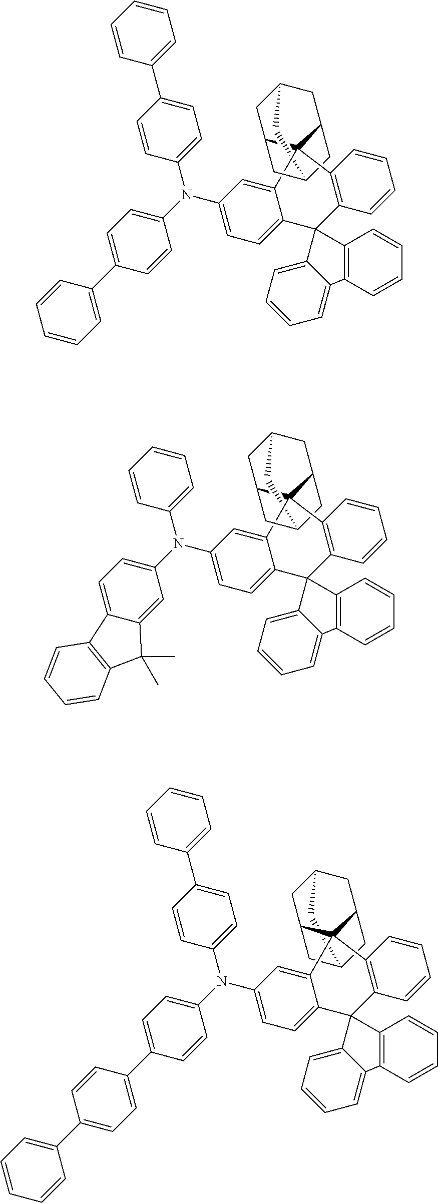
- the compound can be selected from the group consisting of:
- T is a halogen, preferably bromo, or chloro, and the definitions of the other substituents are the same as described above
- the compound of Chemical Formula 1 is prepared by coupling starting materials through a Suzuki coupling reaction.
- a Suzuki coupling reaction is preferably carried out in the presence of a palladium catalyst and a base, and a reactive group for the Suzuki coupling reaction can be modified as known in the art.
- the above preparation method may be further embodied in the Preparation Examples described hereinafter.
- an organic light emitting device including a compound of Chemical Formula 1 described above.
- an organic light emitting device including a first electrode; a second electrode that is provided opposite to the first electrode; and one or more organic material layers that are provided between the first electrode and the second electrode, wherein one or more layers of the organic material layers include the compound of Chemical Formula 1.
- the compound of Chemical Formula 1 has excellent sublimation property and chemical structural stability through introduction of the bulky and rigid structure of adamantane, and thus has excellent thermal stability. Therefore, the efficiency and lifetime may be improved when an organic light emitting device including the compound of Chemical Formula 1 is produced.
- the organic material layer of the organic light emitting device of the present disclosure may have a single-layer structure, or it may have a multilayered structure in which two or more organic material layers are stacked.
- the organic light emitting device of the present disclosure may have a structure comprising a hole injection layer, a hole transport layer, a light emitting layer, an electron transport layer, an electron injection layer and the like as the organic material layer.
- the structure of the organic light emitting device is not limited thereto, and it may include a smaller number of organic material layers.
- the organic material layer may include a hole injection layer, a hole transport layer, a layer for simultaneously performing hole injection and transport, wherein the hole injection layer, the hole transport layer, the layer for simultaneously performing hole injection and transport may include the compound of Chemical Formula 1.
- the organic material layer may include a light emitting layer, wherein the light emitting layer may include the compound of Chemical Formula 1.
- the organic material layer may include an electron transport layer, or an electron injection layer, wherein the electron transport layer, or the electron injection layer may include the compound of Chemical Formula 1.
- the electron transport layer, the electron injection layer, or the layer for simultaneously performing electron transport and electron injection may include the compound of Chemical Formula 1.
- the organic material layer may include a light emitting layer or an electron transport layer, wherein the electron transport layer may include the compound of Chemical Formula 1.
- the organic light emitting device according to the present disclosure may be a normal type organic light emitting device in which an anode, one or more organic material layers, and a cathode are sequentially stacked on a substrate. Further, the organic light emitting device according to the present disclosure may be an inverted type organic light emitting device in which a cathode, one or more organic material layers, and an anode are sequentially stacked on a substrate. For example, the structure of an organic light emitting device according to an embodiment of the present disclosure is illustrated in FIGS. 1 and 2 .
- FIG. 1 shows an example of an organic light emitting device comprising a substrate 1 , an anode 2 , a light emitting layer 3 , and a cathode 4 .
- the compound of Chemical Formula 1 may be included in the light emitting layer.
- FIG. 2 shows an example of an organic light emitting device comprising a substrate 1 , an anode 2 , a hole injection layer 5 , a hole transport layer 6 , a light emitting layer 7 , an electron transport layer 8 , and a cathode 4 .
- the compound of Chemical Formula 1 may be included in one or more layers of the hole injection layer, the hole transport layer, the light emitting layer and the electron transport layer.
- the organic light emitting device according to the present disclosure may be manufactured by materials and methods known in the art, except that one or more layers of the organic material layers include the compound of Chemical Formula 1.
- the organic material layers may be formed of the same material or different materials.
- the organic light emitting device can be manufactured by sequentially stacking a first electrode, an organic material layer and a second electrode on a substrate.
- the organic light emitting device may be manufactured by depositing a metal, metal oxides having conductivity, or an alloy thereof on the substrate using a PVD (physical vapor deposition) method such as a sputtering method or an e-beam evaporation method to form an anode, forming organic material layers including the hole injection layer, the hole transport layer, the light emitting layer and the electron transport layer thereon, and then depositing a material that can be used as the cathode thereon.
- the organic light emitting device may be manufactured by sequentially depositing a cathode material, an organic material layer and an anode material on a substrate.
- the compound of Chemical Formula 1 may be formed into an organic material layer by a solution coating method as well as a vacuum deposition method at the time of manufacturing an organic light emitting device.
- the solution coating method means a spin coating, a dip coating, a doctor blading, an inkjet printing, a screen printing, a spray method, a roll coating, or the like, but is not limited thereto.
- the organic light emitting device may be manufactured by sequentially depositing a cathode material, an organic material layer and an anode material on a substrate (International Publication WO2003/012890).
- the manufacturing method is not limited thereto.
- the first electrode is an anode
- the second electrode is a cathode
- the first electrode is a cathode and the second electrode is an anode
- anode material generally, a material having a large work function is preferably used so that holes can be smoothly injected into the organic material layer.
- the anode material include metals such as vanadium, chrome, copper, zinc, and gold, or an alloy thereof; metal oxides such as zinc oxides, indium oxides, indium tin oxides (ITO), and indium zinc oxides (IZO); a combination of metals and oxides, such as ZnO:Al or SnO 2 :Sb; conductive polymers such as poly(3-methylthiophene), poly[3,4-(ethylene-1,2-dioxy)thiophene](PEDOT), polypyrrole, and polyaniline, and the like, but are not limited thereto.
- the cathode material generally, a material having a small work function is preferably used so that electrons can be easily injected into the organic material layer.
- the cathode material include metals such as magnesium, calcium, sodium, potassium, titanium, indium, yttrium, lithium, gadolinium, aluminum, silver, tin, and lead, or an alloy thereof; a multilayered structure material such as LiF/AI or LiO 2 /Al, and the like, but are not limited thereto.
- the hole injection layer is a layer for injecting holes from the electrode, and the hole injection material is preferably a compound which has a capability of transporting the holes, thus has a hole injecting effect in the anode and an excellent hole injecting effect to the light emitting layer or the light emitting material, prevents excitons produced in the light emitting layer from moving to a hole injection layer or the electron injection material, and further is excellent in the ability to form a thin film. It is preferable that a HOMO (highest occupied molecular orbital) of the hole injection material is between the work function of the anode material and a HOMO of a peripheral organic material layer.
- a HOMO highest occupied molecular orbital
- the hole injection material examples include metal porphyrine, oligothiophene, an arylamine-based organic material, a hexanitrilehexaazatriphenylene-based organic material, a quinacridone-based organic material, a perylene-based organic material, anthraquinone, polyaniline and polythiophene-based conductive compound, and the like, but are not limited thereto.
- the hole transport layer is a layer that receives holes from a hole injection layer and transports the holes to the light emitting layer.
- the hole transport material is suitably a material having large mobility to the holes, which may receive holes from the anode or the hole injection layer and transfer the holes to the light emitting layer.
- Specific examples thereof include an arylamine-based organic material, a conductive compound, a block copolymer in which a conjugate portion and a non-conjugate portion are present together, and the like, but are not limited thereto.
- the light emitting material is preferably a material which may receive holes and electrons transported from a hole transport layer and an electron transport layer, respectively, and combine the holes and the electrons to emit light in a visible ray region, and has good quantum efficiency to fluorescence or phosphorescence.
- the light emitting material examples include an 8-hydroxy-quinoline aluminum complex (Alq 3 ); a carbazole-based compound; a dimerized styryl compound; BAlq; a 10-hydroxybenzoquinoline-metal compound; a benzoxazole, benzthiazole and benzimidazole-based compound; a poly(p-phenylenevinylene)(PPV)-based polymer; a Spiro compound; polyfluorene, lubrene, and the like, but are not limited thereto.
- Alq 3 8-hydroxy-quinoline aluminum complex
- a carbazole-based compound a dimerized styryl compound
- BAlq a 10-hydroxybenzoquinoline-metal compound
- a benzoxazole, benzthiazole and benzimidazole-based compound a poly(p-phenylenevinylene)(PPV)-based polymer
- Spiro compound polyfluorene, lubrene, and the like
- the light emitting layer may include a host material and a dopant material.
- the host material may be a fused aromatic ring derivative, a heterocycle-containing compound or the like.
- the fused aromatic ring derivatives include anthracene derivatives, pyrene derivatives, naphthalene derivatives, pentacene derivatives, phenanthrene compounds, fluoranthene compounds, and the like.
- the heterocyclic-containing compounds include carbazole derivatives, dibenzofuran derivatives, ladder-type furan compounds, pyrimidine derivatives, and the like, but are not limited thereto.
- the dopant material examples include an aromatic amine derivative, a styrylamine compound, a boron complex, a fluoranthene compound, a metal complex, and the like.
- the aromatic amine derivative is a substituted or unsubstituted fused aromatic ring derivative having an arylamino group, and examples thereof include pyrene, anthracene, chrysene, periflanthene and the like, which have an arylamino group.
- the styrylamine compound is a compound where at least one arylvinyl group is substituted in substituted or unsubstituted arylamine, in which one or two or more substituent groups selected from the group consisting of an aryl group, a silyl group, an alkyl group, a cycloalkyl group, and an arylamino group are substituted or unsubstituted.
- substituent groups selected from the group consisting of an aryl group, a silyl group, an alkyl group, a cycloalkyl group, and an arylamino group are substituted or unsubstituted.
- Specific examples thereof include styrylamine, styryldiamine, styryltriamine, styryltetramine, and the like, but are not limited thereto.
- the metal complex includes an iridium complex, a platinum complex, and the like, but is not limited thereto.
- the electron transport layer is a layer which receives electrons from an electron injection layer and transports the electrons to a light emitting layer
- an electron transport material is suitably a material which may receive electrons well from a cathode and transfer the electrons to a light emitting layer, and has a large mobility for electrons.
- Specific examples of the electron transport material include: an Al complex of 8-hydroxyquinoline; a complex including Alq 3 ; an organic radical compound; a hydroxyflavone-metal complex, and the like, but are not limited thereto.
- the electron transport layer may be used with any desired cathode material, as used according to the related art.
- cathode material are a typical material which has a low work function, followed by an aluminum layer or a silver layer.
- specific examples thereof include cesium, barium, calcium, ytterbium, and samarium, in each case followed by an aluminum layer or a silver layer.
- the electron injection layer is a layer which injects electrons from an electrode, and is preferably a compound which has a capability of transporting electrons, has an effect of injecting electrons from a cathode and an excellent effect of injecting electrons into a light emitting layer or a light emitting material, prevents excitons produced from the light emitting layer from moving to a hole injection layer, and is also excellent in the ability to form a thin film.
- the electron injection layer include fluorenone, anthraquinodimethane, diphenoquinone, thiopyran dioxide, oxazole, oxadiazole, triazole, imidazole, perylenetetracarboxylic acid, fluorenylidene methane, anthrone, and the like, and derivatives thereof, a metal complex compound, a nitrogen-containing 5-membered ring derivative, and the like, but are not limited thereto.
- Examples of the metal complex compound include 8-hydroxyquinolinato lithium, bis(8-hydroxyquinolinato)zinc, bis(8-hydroxyquinolinato)copper, bis(8-hydroxyquinolinato)manganese, tris(8-hydroxyquinolinato)aluminum, tris(2-methyl-8-hydroxyquinolinato)aluminum, tris(8-hydroxyquinolinato)gallium, bis(10-hydroxybenzo[h]quinolinato)beryllium, bis(10-hydroxybenzo[h]quinolinato)zinc, bis(2-methyl-8-quinolinato)chlorogallium, bis(2-methyl-8-quinolinato)(o-cresolato)gallium, bis(2-methyl-8-quinolinato)(1-naphtholato)aluminum, bis(2-methyl-8-quinolinato)(2-naphtholato)gallium, and the like, but are not limited thereto.
- the organic light emitting device may be a front side emission type, a back side emission type, or a double side emission type according to the used material.
- the compound of Chemical Formula 1 may be included in an organic solar cell or an organic transistor in addition to an organic light emitting device.
- a glass substrate on which ITO (indium tin oxide) was coated as a thin film to a thickness of 1,000 ⁇ was put into distilled water in which a detergent was dissolved, and ultrasonically cleaned.
- a product manufactured by Fischer Co. was used as the detergent, and as the distilled water, distilled water filtered twice using a filter manufactured by Millipore Co. was used.
- ultrasonic cleaning was repeated twice using distilled water for 10 minutes.
- the substrate was ultrasonically cleaned with solvents of isopropyl alcohol, acetone, and methanol, dried, and then transferred to a plasma cleaner. In addition, the substrate was cleaned for 5 minutes using oxygen plasma and then transferred to a vacuum depositor.
- a compound [H1-A] below was thermally vacuum-deposited to a thickness of 600 ⁇ to form a hole injection layer.
- the compound 1 prepared in Preparation Example 1 was vacuum-deposited on the hole injection layer to form a hole transport layer.
- a compound [BH] below and a compound [BD] below were vacuum-deposited at a ratio of 25:1 to a thickness of 200 ⁇ on the hole transport layer to form a light emitting layer.
- a compound [ET] below and a compound [LiQ] (lithiumquinolate) below were vacuum-deposited at a ratio of 1:1 to form an electron injection and transport layer with a thickness of 150 ⁇ .
- Lithium fluoride (LiF) and aluminum were sequentially deposited to have a thickness of 10 ⁇ and 1,000 ⁇ , respectively, on the electron injection and transport layer, thereby forming a cathode.
- the vapor deposition rate of the organic material was maintained at 0.4 to 0.9 ⁇ /sec
- the deposition rates of lithium fluoride and aluminum of the cathode were maintained at 0.3 ⁇ /sec and at 2 ⁇ /sec, respectively
- the degree of vacuum during the deposition was maintained at 1 ⁇ 10 ⁇ 7 to 5 ⁇ 10 ⁇ 8 torr, thereby manufacturing an organic light emitting device.
- the organic light emitting devices were manufactured in the same manner as in Experimental Example 1, except that the compounds shown in Table 1 below were used instead of the compound in Experimental Example 1.
- the organic light emitting devices were manufactured in the same manner as in Experimental Example 1, except that the compounds shown in Table 1 below were used instead of the compound in Experimental Example 1.
- the compounds of HT-01 to HT-06 used in Table 1 below are as follows.
- the driving voltage and emission efficiency were measure at a current density of 10 mA/cm 2 , and the time (LT 98 ) required for the luminance to be reduced to 98% of the initial luminance was measured at a current density of 20 mA/cm 2 , and the results are shown in Table 1 below.
- substrate 2 anode 3: light emitting layer 4: cathode 5: hole injection layer 6: hole transport layer 7: light emitting layer 8. electron transport layer
Landscapes
- Chemical & Material Sciences (AREA)
- Organic Chemistry (AREA)
- Engineering & Computer Science (AREA)
- Materials Engineering (AREA)
- Physics & Mathematics (AREA)
- Spectroscopy & Molecular Physics (AREA)
- Electroluminescent Light Sources (AREA)
Abstract

Description

-
- in the Chemical Formula 1,
- Q1 and Q2 are each independently a C6-30 aromatic ring;
- a and b are each independently an integer of 0 to 3;
- X is a single bond; CR3R4; SiR5R6; NR7; O; S; SO2; or a substituent group of the following
Chemical Formula 2,

-
- R1 to R7 are each independently hydrogen; deuterium; a substituted or unsubstituted C1-60 alkyl; a substituted or unsubstituted C1-60 alkoxy; a substituted or unsubstituted C6-60 aryl; a substituted or unsubstituted C5-60 heteroaryl containing one or more heteroatoms selected from the group consisting of N, O and S; or may be bonded to adjacent groups to form a ring,
- L1 to L3 are each independently a single bond; a substituted or unsubstituted C6-60 arylene; or a substituted or unsubstituted C2-60 heteroarylene containing any one or more heteroatoms selected from the group consisting of N, O and S, and
- Ar1 and Ar2 are each independently a substituted or unsubstituted C6-60 aryl; a substituted or unsubstituted C2-60 heteroaryl containing one or more heteroatoms selected from the group consisting of N, O and S; a substituted or unsubstituted C1-30 alkyl silyl; or a substituted or unsubstituted C5-30 aryl silyl, provided that diphenylfluorene is excluded.
means a bond linked to another substituent group.


and the like can be formed. However, the structure is not limited thereto.


-
- in the Chemical Formulas 1-1 to 1-7,
- a, b, R1, R2, L1 to L3, Ar1 and Ar2 are the same as defined above.


in the


| TABLE 1 | ||||
| Current | Life Time(hr) | |||
| Hole transport | Voltage | efficiency | LT98 at | |
| Category | layer | (V) | (cd/A) | 20 mA/cm2 |
| | Compound | 1 | 3.71 | 5.64 | 70 |
| Example 1 | |||||
| | Compound | 2 | 3.72 | 5.50 | 72 |
| Example 2 | |||||
| | Compound | 3 | 3.77 | 5.55 | 75 |
| Example 3 | |||||
| | Compound | 4 | 3.61 | 5.51 | 76 |
| Example 4 | |||||
| | Compound | 5 | 3.68 | 5.62 | 71 |
| Example 5 | |||||
| | Compound | 6 | 3.76 | 5.60 | 70 |
| Example 6 | |||||
| | Compound | 7 | 3.80 | 5.66 | 69 |
| Example 7 | |||||
| | Compound | 8 | 3.74 | 5.69 | 77 |
| Example 8 | |||||
| Experimental | Compound 9 | 3.69 | 5.61 | 80 | |
| Example 9 | |||||
| Experimental | Compound 10 | 3.66 | 5.59 | 71 | |
| Example 10 | |||||
| Experimental | Compound 11 | 3.70 | 5.70 | 76 | |
| Example 11 | |||||
| Experimental | Compound 12 | 3.60 | 5.67 | 75 | |
| Example 12 | |||||
| Experimental | Compound 13 | 3.82 | 5.66 | 68 | |
| Example 13 | |||||
| Experimental | Compound 14 | 3.83 | 5.79 | 66 | |
| Example 14 | |||||
| Experimental | Compound 15 | 3.75 | 5.71 | 74 | |
| Example 15 | |||||
| Experimental | Compound 16 | 3.73 | 5.66 | 73 | |
| Example 16 | |||||
| Comparative | HT-01 | 4.71 | 4.42 | 30 | |
| Example 1 | |||||
| Comparative | HT-02 | 4.80 | 4.40 | 31 | |
| Example 2 | |||||
| Comparative | HT-03 | 4.81 | 4.44 | 35 | |
| Example 3 | |||||
| Comparative | HT-04 | 4.88 | 4.45 | 30 | |
| Example 4 | |||||
| Comparative | HT-05 | 4.90 | 4.50 | 28 | |
| Example 5 | |||||
| Comparative | HT-06 | 4.86 | 4.52 | 25 | |
| Example 6 | |||||
| 1: | substrate |
| 2: | anode |
| 3: | light emitting layer |
| 4: | cathode |
| 5: | hole injection layer |
| 6: | hole transport layer |
| 7: | |
| 8. | electron transport layer |
Claims (9)


Applications Claiming Priority (3)
| Application Number | Priority Date | Filing Date | Title |
|---|---|---|---|
| KR20180105513 | 2018-09-04 | ||
| KR10-2018-0105513 | 2018-09-04 | ||
| PCT/KR2019/011397 WO2020050623A1 (en) | 2018-09-04 | 2019-09-04 | Novel compound and organic light emitting device using same |
Publications (2)
| Publication Number | Publication Date |
|---|---|
| US20210130295A1 US20210130295A1 (en) | 2021-05-06 |
| US12157724B2 true US12157724B2 (en) | 2024-12-03 |
Family
ID=69722937
Family Applications (1)
| Application Number | Title | Priority Date | Filing Date |
|---|---|---|---|
| US17/050,328 Active 2042-05-20 US12157724B2 (en) | 2018-09-04 | 2019-09-04 | Compound and organic light emitting device comprising the same |
Country Status (4)
| Country | Link |
|---|---|
| US (1) | US12157724B2 (en) |
| KR (1) | KR102289383B1 (en) |
| CN (1) | CN112055705B (en) |
| WO (1) | WO2020050623A1 (en) |
Families Citing this family (19)
| Publication number | Priority date | Publication date | Assignee | Title |
|---|---|---|---|---|
| KR102618829B1 (en) * | 2019-03-08 | 2023-12-29 | 주식회사 엘지화학 | Compound and organic light emitting device comprising the same |
| CN111635323B (en) * | 2019-06-14 | 2021-04-13 | 陕西莱特光电材料股份有限公司 | Nitrogen-containing compound, electronic component, and electronic device |
| CN110467536B (en) * | 2019-06-14 | 2020-06-30 | 陕西莱特光电材料股份有限公司 | Nitrogen-containing compounds, organic electroluminescent devices and photoelectric conversion devices |
| KR102826881B1 (en) * | 2019-08-27 | 2025-07-01 | 솔루스첨단소재 주식회사 | Organic compound and organic electroluminescent device using the same |
| CN111138297B (en) | 2019-10-31 | 2021-01-08 | 陕西莱特光电材料股份有限公司 | Nitrogen-containing compound, electronic component, and electronic device |
| CN111138298B (en) * | 2019-12-31 | 2020-12-04 | 陕西莱特光电材料股份有限公司 | Nitrogen-containing compounds, electronic components and electronic devices |
| KR20210122382A (en) * | 2020-03-31 | 2021-10-12 | 덕산네오룩스 주식회사 | Compound for organic electronic element, organic electronic element using the same, and an electronic device thereof |
| CN111995533B (en) * | 2020-04-27 | 2022-01-28 | 陕西莱特光电材料股份有限公司 | Nitrogen-containing compound, electronic component, and electronic device |
| KR102877612B1 (en) * | 2020-05-07 | 2025-10-29 | 삼성디스플레이 주식회사 | Heterocyclic compound and light emitting device including the same |
| CN111848501B (en) * | 2020-05-08 | 2021-06-01 | 陕西莱特光电材料股份有限公司 | Nitrogen-containing compound, and electronic element and electronic device using same |
| KR102640225B1 (en) * | 2020-07-07 | 2024-02-23 | 주식회사 엘지화학 | Novel compound and organic light emitting device comprising the same |
| CN111777516B (en) * | 2020-07-28 | 2023-04-07 | 吉林奥来德光电材料股份有限公司 | Organic light-emitting compound and preparation method and application thereof |
| KR102899742B1 (en) * | 2020-09-28 | 2025-12-11 | 주식회사 엘지화학 | Novel compound and organic light emitting device comprising the same |
| KR102860315B1 (en) | 2020-10-08 | 2025-09-16 | 삼성디스플레이 주식회사 | heterocyclic compound, light emitting device including the condensed cyclic compound and electronic apparatus including the light emitting device |
| CN114478267A (en) * | 2020-10-26 | 2022-05-13 | 北京鼎材科技有限公司 | Organic compounds for light-emitting devices and organic electroluminescent devices |
| KR20230098799A (en) * | 2020-11-06 | 2023-07-04 | 호도가야 가가쿠 고교 가부시키가이샤 | organic electroluminescence device |
| WO2023085670A1 (en) * | 2021-11-09 | 2023-05-19 | 주식회사 엘지화학 | Novel compound and organic light-emitting device comprising same |
| KR20240127904A (en) * | 2023-02-16 | 2024-08-23 | 주식회사 엘지화학 | Novel compound and organic light emitting device comprising the same |
| CN118993901A (en) * | 2023-05-18 | 2024-11-22 | 陕西莱特光电材料股份有限公司 | Organic compound, and electronic component and electronic device using same |
Citations (11)
| Publication number | Priority date | Publication date | Assignee | Title |
|---|---|---|---|---|
| KR20000051826A (en) | 1999-01-27 | 2000-08-16 | 성재갑 | New organomattalic complex molecule for the fabrication of organic light emitting diodes |
| WO2003012890A2 (en) | 2001-07-20 | 2003-02-13 | Novaled Gmbh | Light emitting component with organic layers |
| KR20080071723A (en) | 2007-01-31 | 2008-08-05 | 동우 화인켐 주식회사 | Asymmetric mono or dianthracene derivatives having adamantane groups and organic electroluminescent devices using the same |
| KR20150139969A (en) | 2013-04-11 | 2015-12-14 | 신닛테츠 수미킨 가가쿠 가부시키가이샤 | Adamantane compound for organic electroluminescent elements, and organic electroluminescent element |
| KR20160032020A (en) | 2013-07-09 | 2016-03-23 | 토소가부시키가이샤 | Cyclic azine compound having adamantyl group, production method, and organic electroluminescent element containing said compound as constituent |
| KR20170080432A (en) | 2015-12-31 | 2017-07-10 | 머티어리얼사이언스 주식회사 | organic electroluminescent device |
| KR20170136980A (en) | 2016-06-02 | 2017-12-12 | 주식회사 엘지화학 | Compound and organic electronic device comprising the same |
| KR20180078177A (en) | 2016-12-29 | 2018-07-09 | 머티어리얼사이언스 주식회사 | Organic compound and organic electroluminescent device comprising the same |
| KR20180082710A (en) | 2017-01-10 | 2018-07-19 | 삼성디스플레이 주식회사 | Organic electroluminescence device |
| CN110128279A (en) | 2019-06-14 | 2019-08-16 | 陕西莱特光电材料股份有限公司 | Electroluminescent organic material and organic electroluminescence device comprising the material |
| CN110467536A (en) | 2019-06-14 | 2019-11-19 | 陕西莱特光电材料股份有限公司 | Nitrogenous compound, organic electroluminescence device and photoelectric conversion device |
-
2019
- 2019-09-04 WO PCT/KR2019/011397 patent/WO2020050623A1/en not_active Ceased
- 2019-09-04 KR KR1020190109421A patent/KR102289383B1/en active Active
- 2019-09-04 CN CN201980026299.9A patent/CN112055705B/en active Active
- 2019-09-04 US US17/050,328 patent/US12157724B2/en active Active
Patent Citations (18)
| Publication number | Priority date | Publication date | Assignee | Title |
|---|---|---|---|---|
| KR20000051826A (en) | 1999-01-27 | 2000-08-16 | 성재갑 | New organomattalic complex molecule for the fabrication of organic light emitting diodes |
| WO2003012890A2 (en) | 2001-07-20 | 2003-02-13 | Novaled Gmbh | Light emitting component with organic layers |
| US7274141B2 (en) | 2001-07-20 | 2007-09-25 | Novaled Gmbh | Inverted organic light emitting diode with doped layers |
| KR20080071723A (en) | 2007-01-31 | 2008-08-05 | 동우 화인켐 주식회사 | Asymmetric mono or dianthracene derivatives having adamantane groups and organic electroluminescent devices using the same |
| KR20150139969A (en) | 2013-04-11 | 2015-12-14 | 신닛테츠 수미킨 가가쿠 가부시키가이샤 | Adamantane compound for organic electroluminescent elements, and organic electroluminescent element |
| CN105190930A (en) | 2013-04-11 | 2015-12-23 | 新日铁住金化学株式会社 | Adamantane compound for organic electroluminescent elements, and organic electroluminescent element |
| US20160072064A1 (en) | 2013-04-11 | 2016-03-10 | Nippon Steel & Sumikin Chemical Co., Ltd. | Adamantane compound for organic electroluminescent elements, and organic electroluminescent element |
| US20160372678A1 (en) | 2013-07-09 | 2016-12-22 | Tosoh Corporation | Cyclic azine compound having adamantyl group, production method, and organic electroluminescent device containing it as constituent component |
| KR20160032020A (en) | 2013-07-09 | 2016-03-23 | 토소가부시키가이샤 | Cyclic azine compound having adamantyl group, production method, and organic electroluminescent element containing said compound as constituent |
| KR20170080432A (en) | 2015-12-31 | 2017-07-10 | 머티어리얼사이언스 주식회사 | organic electroluminescent device |
| US20190016666A1 (en) | 2015-12-31 | 2019-01-17 | Material Science Co., Ltd. | Organic compound and organic electroluminescent element comprising same |
| KR20170136980A (en) | 2016-06-02 | 2017-12-12 | 주식회사 엘지화학 | Compound and organic electronic device comprising the same |
| CN107459466A (en) | 2016-06-02 | 2017-12-12 | 株式会社Lg化学 | Compound and organic electronic components containing it |
| KR20180078177A (en) | 2016-12-29 | 2018-07-09 | 머티어리얼사이언스 주식회사 | Organic compound and organic electroluminescent device comprising the same |
| KR20180082710A (en) | 2017-01-10 | 2018-07-19 | 삼성디스플레이 주식회사 | Organic electroluminescence device |
| CN110128279A (en) | 2019-06-14 | 2019-08-16 | 陕西莱特光电材料股份有限公司 | Electroluminescent organic material and organic electroluminescence device comprising the material |
| CN110467536A (en) | 2019-06-14 | 2019-11-19 | 陕西莱特光电材料股份有限公司 | Nitrogenous compound, organic electroluminescence device and photoelectric conversion device |
| US20200395544A1 (en) * | 2019-06-14 | 2020-12-17 | Shaanxi Lighte Optoelectronics Material Co., Ltd. | Nitrogen-containing compound, organic electroluminescent device and photoelectric conversion device |
Non-Patent Citations (4)
| Title |
|---|
| Chen, C.-H. et al., "Synthesis and characterization of spiro (adamantane-2, 9′-fluorene)-based triaryldiamines: thermally stable hole-transporting materials", Synthetic metals, 2004, vol. 143-2, pp. 215-220. |
| International Search Report from PCT/KR2019/011397, dated Dec. 20, 2019. |
| Shu et al., Synthesis and characterization of spiro(adamantane-2,9-fluorene)-based triaryldiamines: thermally stable hole-transporting materials; 2004, Synthetic Metals 143 (2004) 215-220 (Year: 2004). * |
| Written Opinion of the ISA from PCT/KR2019/011397, dated Dec. 20, 2019. |
Also Published As
| Publication number | Publication date |
|---|---|
| WO2020050623A1 (en) | 2020-03-12 |
| CN112055705A (en) | 2020-12-08 |
| US20210130295A1 (en) | 2021-05-06 |
| KR102289383B1 (en) | 2021-08-12 |
| KR20200027444A (en) | 2020-03-12 |
| CN112055705B (en) | 2024-03-19 |
Similar Documents
| Publication | Publication Date | Title |
|---|---|---|
| US12157724B2 (en) | Compound and organic light emitting device comprising the same | |
| US11997925B2 (en) | Cyclic compound and organic light emitting device comprising same | |
| US12275736B2 (en) | Compound and organic light emitting device comprising the same | |
| US12060372B2 (en) | Compound and organic light emitting device comprising the same | |
| US11081655B2 (en) | Heterocyclic compound and organic light emitting device using the same | |
| US12509464B2 (en) | Organic light emitting device | |
| US11542258B2 (en) | Heterocyclic compound and organic light emitting device comprising the same | |
| US11453650B2 (en) | Heterocyclic compound and organic light emitting device comprising the same | |
| US12058931B2 (en) | Heterocyclic compound and organic light emitting device comprising same | |
| US11228001B2 (en) | Hetero-cyclic compound and organic light emitting device comprising the same | |
| US20220085300A1 (en) | Organic light emitting device | |
| US11925113B2 (en) | Heterocyclic compound and organic light emitting device comprising the same | |
| US20210280794A1 (en) | Novel compound and organic light emitting device comprising the same | |
| US11795161B2 (en) | Compound and organic light emitting device comprising same | |
| US12133459B2 (en) | Heterocyclic compound and organic light emitting device comprising same | |
| US20220056048A1 (en) | Novel compound and organic light emitting device comprising the same | |
| US11261176B2 (en) | Amine-based compound and organic light emitting device using the same | |
| US11980090B2 (en) | Compound and organic light emitting device comprising the same | |
| US11778909B2 (en) | Compound and organic light emitting device comprising the same | |
| US20240292744A1 (en) | Compound and organic light emitting device comprising the same | |
| US20240114776A1 (en) | Compound and organic light emitting device comprising the same | |
| US20240381763A1 (en) | Novel compound and organic light emitting device comprising the same | |
| US12202838B2 (en) | Heterocyclic compound and organic light emitting device comprising same | |
| US12598910B2 (en) | Compound and organic light emitting device comprising same | |
| US11832517B2 (en) | Heterocyclic compound and organic light emitting device comprising same |
Legal Events
| Date | Code | Title | Description |
|---|---|---|---|
| AS | Assignment |
Owner name: LG CHEM, LTD., KOREA, REPUBLIC OF Free format text: ASSIGNMENT OF ASSIGNORS INTEREST;ASSIGNORS:KIM, YOUNG SEOK;KIM, KONGKYEOM;KOO, KI DONG;AND OTHERS;SIGNING DATES FROM 20200915 TO 20200916;REEL/FRAME:054153/0850 |
|
| FEPP | Fee payment procedure |
Free format text: ENTITY STATUS SET TO UNDISCOUNTED (ORIGINAL EVENT CODE: BIG.); ENTITY STATUS OF PATENT OWNER: LARGE ENTITY |
|
| STPP | Information on status: patent application and granting procedure in general |
Free format text: APPLICATION DISPATCHED FROM PREEXAM, NOT YET DOCKETED |
|
| STPP | Information on status: patent application and granting procedure in general |
Free format text: DOCKETED NEW CASE - READY FOR EXAMINATION |
|
| STPP | Information on status: patent application and granting procedure in general |
Free format text: NON FINAL ACTION MAILED |
|
| STPP | Information on status: patent application and granting procedure in general |
Free format text: RESPONSE TO NON-FINAL OFFICE ACTION ENTERED AND FORWARDED TO EXAMINER |
|
| STPP | Information on status: patent application and granting procedure in general |
Free format text: NOTICE OF ALLOWANCE MAILED -- APPLICATION RECEIVED IN OFFICE OF PUBLICATIONS |
|
| ZAAB | Notice of allowance mailed |
Free format text: ORIGINAL CODE: MN/=. |
|
| STPP | Information on status: patent application and granting procedure in general |
Free format text: PUBLICATIONS -- ISSUE FEE PAYMENT RECEIVED |
|
| STPP | Information on status: patent application and granting procedure in general |
Free format text: PUBLICATIONS -- ISSUE FEE PAYMENT VERIFIED |
|
| STCF | Information on status: patent grant |
Free format text: PATENTED CASE |