US12153123B2 - DNN-based human face classification - Google Patents
DNN-based human face classification Download PDFInfo
- Publication number
- US12153123B2 US12153123B2 US17/229,529 US202117229529A US12153123B2 US 12153123 B2 US12153123 B2 US 12153123B2 US 202117229529 A US202117229529 A US 202117229529A US 12153123 B2 US12153123 B2 US 12153123B2
- Authority
- US
- United States
- Prior art keywords
- signal
- radar
- frequency
- signals
- antenna elements
- Prior art date
- Legal status (The legal status is an assumption and is not a legal conclusion. Google has not performed a legal analysis and makes no representation as to the accuracy of the status listed.)
- Active, expires
Links
Images


Classifications
-
- G—PHYSICS
- G01—MEASURING; TESTING
- G01S—RADIO DIRECTION-FINDING; RADIO NAVIGATION; DETERMINING DISTANCE OR VELOCITY BY USE OF RADIO WAVES; LOCATING OR PRESENCE-DETECTING BY USE OF THE REFLECTION OR RERADIATION OF RADIO WAVES; ANALOGOUS ARRANGEMENTS USING OTHER WAVES
- G01S13/00—Systems using the reflection or reradiation of radio waves, e.g. radar systems; Analogous systems using reflection or reradiation of waves whose nature or wavelength is irrelevant or unspecified
- G01S13/02—Systems using reflection of radio waves, e.g. primary radar systems; Analogous systems
- G01S13/06—Systems determining position data of a target
- G01S13/08—Systems for measuring distance only
- G01S13/32—Systems for measuring distance only using transmission of continuous waves, whether amplitude-, frequency-, or phase-modulated, or unmodulated
- G01S13/34—Systems for measuring distance only using transmission of continuous waves, whether amplitude-, frequency-, or phase-modulated, or unmodulated using transmission of continuous, frequency-modulated waves while heterodyning the received signal, or a signal derived therefrom, with a locally-generated signal related to the contemporaneously transmitted signal
- G01S13/342—Systems for measuring distance only using transmission of continuous waves, whether amplitude-, frequency-, or phase-modulated, or unmodulated using transmission of continuous, frequency-modulated waves while heterodyning the received signal, or a signal derived therefrom, with a locally-generated signal related to the contemporaneously transmitted signal using sinusoidal modulation
-
- G—PHYSICS
- G01—MEASURING; TESTING
- G01S—RADIO DIRECTION-FINDING; RADIO NAVIGATION; DETERMINING DISTANCE OR VELOCITY BY USE OF RADIO WAVES; LOCATING OR PRESENCE-DETECTING BY USE OF THE REFLECTION OR RERADIATION OF RADIO WAVES; ANALOGOUS ARRANGEMENTS USING OTHER WAVES
- G01S13/00—Systems using the reflection or reradiation of radio waves, e.g. radar systems; Analogous systems using reflection or reradiation of waves whose nature or wavelength is irrelevant or unspecified
- G01S13/02—Systems using reflection of radio waves, e.g. primary radar systems; Analogous systems
- G01S13/06—Systems determining position data of a target
- G01S13/08—Systems for measuring distance only
- G01S13/32—Systems for measuring distance only using transmission of continuous waves, whether amplitude-, frequency-, or phase-modulated, or unmodulated
- G01S13/34—Systems for measuring distance only using transmission of continuous waves, whether amplitude-, frequency-, or phase-modulated, or unmodulated using transmission of continuous, frequency-modulated waves while heterodyning the received signal, or a signal derived therefrom, with a locally-generated signal related to the contemporaneously transmitted signal
- G01S13/343—Systems for measuring distance only using transmission of continuous waves, whether amplitude-, frequency-, or phase-modulated, or unmodulated using transmission of continuous, frequency-modulated waves while heterodyning the received signal, or a signal derived therefrom, with a locally-generated signal related to the contemporaneously transmitted signal using sawtooth modulation
-
- G—PHYSICS
- G01—MEASURING; TESTING
- G01S—RADIO DIRECTION-FINDING; RADIO NAVIGATION; DETERMINING DISTANCE OR VELOCITY BY USE OF RADIO WAVES; LOCATING OR PRESENCE-DETECTING BY USE OF THE REFLECTION OR RERADIATION OF RADIO WAVES; ANALOGOUS ARRANGEMENTS USING OTHER WAVES
- G01S13/00—Systems using the reflection or reradiation of radio waves, e.g. radar systems; Analogous systems using reflection or reradiation of waves whose nature or wavelength is irrelevant or unspecified
- G01S13/88—Radar or analogous systems specially adapted for specific applications
-
- G—PHYSICS
- G01—MEASURING; TESTING
- G01S—RADIO DIRECTION-FINDING; RADIO NAVIGATION; DETERMINING DISTANCE OR VELOCITY BY USE OF RADIO WAVES; LOCATING OR PRESENCE-DETECTING BY USE OF THE REFLECTION OR RERADIATION OF RADIO WAVES; ANALOGOUS ARRANGEMENTS USING OTHER WAVES
- G01S7/00—Details of systems according to groups G01S13/00, G01S15/00, G01S17/00
- G01S7/02—Details of systems according to groups G01S13/00, G01S15/00, G01S17/00 of systems according to group G01S13/00
- G01S7/35—Details of non-pulse systems
- G01S7/352—Receivers
- G01S7/356—Receivers involving particularities of FFT processing
-
- G—PHYSICS
- G01—MEASURING; TESTING
- G01S—RADIO DIRECTION-FINDING; RADIO NAVIGATION; DETERMINING DISTANCE OR VELOCITY BY USE OF RADIO WAVES; LOCATING OR PRESENCE-DETECTING BY USE OF THE REFLECTION OR RERADIATION OF RADIO WAVES; ANALOGOUS ARRANGEMENTS USING OTHER WAVES
- G01S7/00—Details of systems according to groups G01S13/00, G01S15/00, G01S17/00
- G01S7/02—Details of systems according to groups G01S13/00, G01S15/00, G01S17/00 of systems according to group G01S13/00
- G01S7/41—Details of systems according to groups G01S13/00, G01S15/00, G01S17/00 of systems according to group G01S13/00 using analysis of echo signal for target characterisation; Target signature; Target cross-section
- G01S7/411—Identification of targets based on measurements of radar reflectivity
- G01S7/412—Identification of targets based on measurements of radar reflectivity based on a comparison between measured values and known or stored values
-
- G—PHYSICS
- G01—MEASURING; TESTING
- G01S—RADIO DIRECTION-FINDING; RADIO NAVIGATION; DETERMINING DISTANCE OR VELOCITY BY USE OF RADIO WAVES; LOCATING OR PRESENCE-DETECTING BY USE OF THE REFLECTION OR RERADIATION OF RADIO WAVES; ANALOGOUS ARRANGEMENTS USING OTHER WAVES
- G01S7/00—Details of systems according to groups G01S13/00, G01S15/00, G01S17/00
- G01S7/02—Details of systems according to groups G01S13/00, G01S15/00, G01S17/00 of systems according to group G01S13/00
- G01S7/41—Details of systems according to groups G01S13/00, G01S15/00, G01S17/00 of systems according to group G01S13/00 using analysis of echo signal for target characterisation; Target signature; Target cross-section
- G01S7/417—Details of systems according to groups G01S13/00, G01S15/00, G01S17/00 of systems according to group G01S13/00 using analysis of echo signal for target characterisation; Target signature; Target cross-section involving the use of neural networks
-
- G—PHYSICS
- G06—COMPUTING OR CALCULATING; COUNTING
- G06F—ELECTRIC DIGITAL DATA PROCESSING
- G06F17/00—Digital computing or data processing equipment or methods, specially adapted for specific functions
- G06F17/10—Complex mathematical operations
- G06F17/14—Fourier, Walsh or analogous domain transformations, e.g. Laplace, Hilbert, Karhunen-Loeve, transforms
- G06F17/141—Discrete Fourier transforms
- G06F17/142—Fast Fourier transforms, e.g. using a Cooley-Tukey type algorithm
-
- G—PHYSICS
- G06—COMPUTING OR CALCULATING; COUNTING
- G06F—ELECTRIC DIGITAL DATA PROCESSING
- G06F18/00—Pattern recognition
- G06F18/20—Analysing
- G06F18/21—Design or setup of recognition systems or techniques; Extraction of features in feature space; Blind source separation
- G06F18/214—Generating training patterns; Bootstrap methods, e.g. bagging or boosting
-
- G—PHYSICS
- G06—COMPUTING OR CALCULATING; COUNTING
- G06F—ELECTRIC DIGITAL DATA PROCESSING
- G06F18/00—Pattern recognition
- G06F18/20—Analysing
- G06F18/24—Classification techniques
- G06F18/241—Classification techniques relating to the classification model, e.g. parametric or non-parametric approaches
- G06F18/2413—Classification techniques relating to the classification model, e.g. parametric or non-parametric approaches based on distances to training or reference patterns
- G06F18/24133—Distances to prototypes
-
- G—PHYSICS
- G06—COMPUTING OR CALCULATING; COUNTING
- G06N—COMPUTING ARRANGEMENTS BASED ON SPECIFIC COMPUTATIONAL MODELS
- G06N3/00—Computing arrangements based on biological models
- G06N3/02—Neural networks
- G06N3/04—Architecture, e.g. interconnection topology
-
- G—PHYSICS
- G06—COMPUTING OR CALCULATING; COUNTING
- G06N—COMPUTING ARRANGEMENTS BASED ON SPECIFIC COMPUTATIONAL MODELS
- G06N3/00—Computing arrangements based on biological models
- G06N3/02—Neural networks
- G06N3/04—Architecture, e.g. interconnection topology
- G06N3/045—Combinations of networks
-
- G—PHYSICS
- G06—COMPUTING OR CALCULATING; COUNTING
- G06N—COMPUTING ARRANGEMENTS BASED ON SPECIFIC COMPUTATIONAL MODELS
- G06N3/00—Computing arrangements based on biological models
- G06N3/02—Neural networks
- G06N3/04—Architecture, e.g. interconnection topology
- G06N3/0499—Feedforward networks
-
- G—PHYSICS
- G06—COMPUTING OR CALCULATING; COUNTING
- G06N—COMPUTING ARRANGEMENTS BASED ON SPECIFIC COMPUTATIONAL MODELS
- G06N3/00—Computing arrangements based on biological models
- G06N3/02—Neural networks
- G06N3/08—Learning methods
- G06N3/084—Backpropagation, e.g. using gradient descent
-
- G—PHYSICS
- G06—COMPUTING OR CALCULATING; COUNTING
- G06N—COMPUTING ARRANGEMENTS BASED ON SPECIFIC COMPUTATIONAL MODELS
- G06N3/00—Computing arrangements based on biological models
- G06N3/02—Neural networks
- G06N3/08—Learning methods
- G06N3/088—Non-supervised learning, e.g. competitive learning
-
- G—PHYSICS
- G06—COMPUTING OR CALCULATING; COUNTING
- G06N—COMPUTING ARRANGEMENTS BASED ON SPECIFIC COMPUTATIONAL MODELS
- G06N3/00—Computing arrangements based on biological models
- G06N3/02—Neural networks
- G06N3/08—Learning methods
- G06N3/09—Supervised learning
-
- G—PHYSICS
- G06—COMPUTING OR CALCULATING; COUNTING
- G06V—IMAGE OR VIDEO RECOGNITION OR UNDERSTANDING
- G06V10/00—Arrangements for image or video recognition or understanding
- G06V10/70—Arrangements for image or video recognition or understanding using pattern recognition or machine learning
- G06V10/82—Arrangements for image or video recognition or understanding using pattern recognition or machine learning using neural networks
-
- G—PHYSICS
- G06—COMPUTING OR CALCULATING; COUNTING
- G06V—IMAGE OR VIDEO RECOGNITION OR UNDERSTANDING
- G06V40/00—Recognition of biometric, human-related or animal-related patterns in image or video data
- G06V40/10—Human or animal bodies, e.g. vehicle occupants or pedestrians; Body parts, e.g. hands
- G06V40/16—Human faces, e.g. facial parts, sketches or expressions
- G06V40/168—Feature extraction; Face representation
- G06V40/171—Local features and components; Facial parts ; Occluding parts, e.g. glasses; Geometrical relationships
-
- G—PHYSICS
- G06—COMPUTING OR CALCULATING; COUNTING
- G06V—IMAGE OR VIDEO RECOGNITION OR UNDERSTANDING
- G06V40/00—Recognition of biometric, human-related or animal-related patterns in image or video data
- G06V40/10—Human or animal bodies, e.g. vehicle occupants or pedestrians; Body parts, e.g. hands
- G06V40/16—Human faces, e.g. facial parts, sketches or expressions
- G06V40/172—Classification, e.g. identification
-
- H—ELECTRICITY
- H03—ELECTRONIC CIRCUITRY
- H03D—DEMODULATION OR TRANSFERENCE OF MODULATION FROM ONE CARRIER TO ANOTHER
- H03D7/00—Transference of modulation from one carrier to another, e.g. frequency-changing
Definitions
- the present disclosure relates to a human face classification, and more specifically, to a deep neural network-based human face classification.
- Radio detection and ranging (i.e., radar) sensors are widely used for many different purposes in various fields. Recently, as the frequency band and the bandwidth used by radar sensors have been expanded to the millimeter wave band, interest in radars with smaller size and higher range resolution has increased. That is, the miniaturization of radar sensors is being achieved, and the radar sensor is expected to be utilized for other purposes.
- the present disclosure describes human face classification.
- a method for extracting target information from signals of a radar and measurement environments includes: transmitting frequency-modulated continuous wave transmit signal using the radar; receiving reflected signal reflected from a human face at multiple antenna elements; multiplying the transmit signal with the reflected signal using a mixer to produce a mixed signal; passing the mixed signal through a low pass filter to produce a baseband signal including sinusoidal signals; extracting a frequency of each sinusoidal signal from the baseband signal to produce extracted frequencies; and measuring a distance between the human face and the radar using the extracted frequencies.
- a method in another implementation, includes: receiving input signal from each of a plurality of receiving antenna elements of the radar, wherein the input signal is a reflected signal from a face; low pass filtering the input signal to produce a filtered output; passing the filtered output through an analog-to-digital converter and sampling at a sampling frequency to produce a discrete filter output; applying a transform to the discrete filter output to calculate a distance between the face and the radar; and applying a false alarm rate detection technique to the transformed output to produce a frequency index corresponding to the distance.
- a non-transitory computer-readable storage medium storing a computer program to extract target information from signals of a radar and measurement environments.
- the computer program includes executable instructions that cause a computer to: transmit frequency-modulated continuous wave transmit signal using the radar; receive reflected signal reflected from a human face at multiple antenna elements; multiply the transmit signal with the reflected signal using a mixer to produce a mixed signal; pass the mixed signal through a low pass filter to produce a baseband signal including sinusoidal signals; extract a frequency of each sinusoidal signal from the baseband signal to produce extracted frequencies; and measure a distance between the human face and the radar using the extracted frequencies.
- FIG. 1 shows the time-frequency slope of the transmitted FMCW radar signal in accordance with one implementation of the present disclosure
- FIG. 2 A is a millimeter wave FMCW radar in accordance with one implementation of the present disclosure
- FIG. 2 B shows a circuit layout of the FMCW radar including a single transmit antenna and three receiving antenna elements in accordance with one implementation of the present disclosure
- FIG. 3 A shows an azimuth angle of the radar with respect to the face
- FIG. 3 B shows an elevation angle of the radar with respect to the face
- FIG. 4 shows a structure of the MLP network in accordance with one implementation of the present disclosure
- FIGS. 5 A to 5 H show the accumulated F(L 3 [n]) of 8 human faces over 20 seconds when the faces are about 30-50 cm away from the center of the radar in accordance with one implementation of the present disclosure
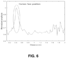
- FIG. 6 shows the F(L 3 [n]) for one subject, when the human face is about 40 cm away from the radar;
- FIG. 7 shows a data vector for training the DNN in accordance with one implementation of the present disclosure
- FIG. 8 shows a process for using only the signal part marked with a red rectangular box in accordance with one implementation of the present disclosure
- FIG. 9 shows an organization of the FFT index corresponding to the distance around the face
- FIG. 10 shows an average face classification performance for 8 different subjects in accordance with one implementation of the present disclosure
- FIG. 11 shows the classification performance in accordance with one implementation of the present disclosure
- FIG. 12 is a flow diagram of a process for extracting target information from the radar signals and signal measurement environments in accordance with one implementation of the present disclosure.
- FIG. 13 is a flow diagram of a process for training the deep neural network (DNN) with acquired radar signal in accordance with one implementation of the present disclosure.
- DNN deep neural network
- the radar sensors are widely used for many different purposes in various fields. As the frequency band and the bandwidth used by radar sensors have been expanded to the millimeter wave band, interest in radars with smaller size and higher range resolution has increased. That is, the miniaturization of radar sensors is being achieved, and the radar sensor is expected to be utilized for purposes other than the traditional purposes. In one case, the radar is being integrated into smartphones for face and gesture recognition. In another case, the ultra-wideband (UWB) radar is being integrated into smartphones to locate other smartphones.
- UWB ultra-wideband
- Certain implementations of the present disclosure provide for classifying human faces using a small-sized millimeter wave radar sensor.
- the radar sensor transmits a frequency-modulated continuous waveform (e.g., operating in the 61 GHz band) and receives reflected signals using spatially separated receiving antenna elements. Because the shape and the composition of the human face varies from person to person, the reflection characteristics of the radar signal are also distinguished from each other.
- the deep neural network can be trained for human face classification. When training DNN with actual radar signals, multiple human faces can be classified with high accuracy.
- machine learning techniques research on target classification using a radar sensor has been actively conducted in recent years. For example, various human behaviors were classified applying machine learning techniques to radar sensor data. Further, some have proposed to identify radar targets, such as pedestrians, cyclists, and automobiles, using automotive radar sensors. Even recently, studies have been conducted to distinguished unmanned aerial vehicles by reflected radar signals. All of these target classification studies are based on the fact that the reflection properties of object are different. Likewise, because the shape and composition of a person's face are also different for each individual, the human face can be sufficiently distinguished if appropriate machine learning technique is applied to radar data. Through face classification using radio waves, the weakness of the camera-based face recognition method can be compensated.
- the radar sensor operates at the center frequency of 61 GHz and transmits a frequency-modulated continuous wave (FMCW). Then, signals reflected on the human face are received by multiple receiving antenna elements. Because the antenna elements are arranged in the elevation and azimuth directions, the spatial facial features of the person are contained in the received signals. Further, because the constituents of the face are different for each person, the reflection characteristics are different for each person. Thus, if signals received from multiple antenna elements are concatenated and used as inputs to the deep neural network (DNN), an effective classifier can be designed to distinguish each person's face.
- DNN deep neural network
- the classification performance of the proposed DNN-based face classification method is evaluated, and is compared with other existing feature-based machine learning techniques.
- the advantage of the proposed DNN-based method is that it does not require a feature extraction stage.
- the applicability of DNN to the radar sensor data has already been confirmed.
- most deep learning-based target classification studies focused on large-scale radar systems operating in low-frequency bands or relatively distant targets.
- Implementations disclosed in Section II describe a signal processing method for extracting target information from radar signals and signal measurement environments.
- Implementations disclosed in Section III describe a method for training the DNN with the acquired radar signal and its classification results.
- Section IV includes a conclusion.
- FIG. 1 shows the time-frequency slope of the transmitted FMCW radar signal, where 1, 2, . . . , N are the indices of each frame. Therefore, the transmitted signal T(t) of a frame is expressed as
- T ⁇ ( t ) A T ⁇ cos ⁇ ( 2 ⁇ ⁇ ⁇ ⁇ ( f c - ⁇ ⁇ ⁇ B 2 ) ⁇ t + ⁇ ⁇ ⁇ ⁇ ⁇ B ⁇ ⁇ ⁇ T ⁇ t 2 ) ⁇ ⁇ ( 0 ⁇ t ⁇ ⁇ ⁇ T ) , ( 1 )
- a T is the amplitude of the transmitted signal
- f c is the center frequency of the modulated signal
- ⁇ B is the operating bandwidth
- ⁇ T is the sweep time.
- the transmitted signal is also referred to as an up-chirp signal because its frequency increases rapidly.
- the received signal R(t) can be expressed as
- L is the amplitude of the signal reflected from the l th target
- f d l is the Doppler frequency caused by the relative velocity between the l th target and the radar
- t d l is the time delay caused by the relative distance between the l th target and the radar.
- the desired signal which contains the information of the l th target, is expressed as d l (t).
- n(t) represents the noise added at the receiving antenna.
- the transmitted signal T(t) is then multiplied with the received signal R(t) by passing through a frequency mixer.
- the output of the mixer M(t) is given as
- M(t) is passed through the low-pass filter.
- the filter output can then be approximated as
- FIG. 2 A is a millimeter wave FMCW radar in accordance with one implementation of the present disclosure.
- FIG. 2 B shows a circuit layout of the FMCW radar including a single transmit antenna and three receiving antenna elements in accordance with one implementation of the present disclosure.
- the FMCW radar uses a single transmit antenna and three receiving antenna elements (two in the azimuth direction and two in the elevation direction, with one in each direction being shared by one antenna element). The distance between adjacent antenna elements is
- f c , ⁇ B, and ⁇ T in Equation (1) are set as 61 GHz, 6 GHz, and 12.5 ms, respectively.
- one frame of the FMCW radar signal is 50 ms long, which consists of a 12.5 ms signal transmission time and a 37.5 ms signal processing time.
- FIGS. 3 A and 3 B an experimental environment is setup as shown in FIGS. 3 A and 3 B and collects reflected radar signals.
- FIG. 3 A shows an azimuth angle of the radar with respect to the face
- FIG. 3 B shows an elevation angle of the radar with respect to the face.
- radar signals are measured by changing the distance between the radar and the face from 30 cm to 50 cm. Further, because the reflected signal can vary depending on the azimuth and elevation angles (e.g., ⁇ and ⁇ in FIGS. 3 A and 3 B ) between the face and the front direction of the radar, the received radar signal is acquired by changing ⁇ and ⁇ from ⁇ 5° to ⁇ 5°.
- FIG. 4 shows one example structure of the MLP network.
- the example structure includes an input layer, multiple hidden layers, and an output layer. Further, each layer is composed of a number of nodes, and each node is connected to nodes of adjacent layers.
- This network shown in FIG. 4 is trained through a repeated process of forward propagation and backward propagation. In the forward propagation, each layer passes its value to the next layer by using weights and an activation function.
- X i (k) and Y o (k) denote the input and output vector at k-th layer
- W (k) denote the weight matrix between the k-th and the (k+1)-th layers.
- the weight values are updated by computing the gradient of the cost function with respect to each weight in the backward propagation. If the weight value before backward propagation is W b , the updated weight after the backward propagation W a is
- W a W b - ⁇ ⁇ ⁇ J ⁇ W b , ( 8 )
- ⁇ denotes the learning rate that determines the speed of the learning
- J denotes the cost function that indicates the error between the trained and the true values.
- epoch forward and backward propagation, which is called an epoch, is repeated several times to train the weight matrix W (k) properly.
- N s denotes the number of sampled points.
- FFT fast Fourier transform
- FIG. 6 shows the F(L 3 [n]) for one subject, when the human face is about 40 cm away from the radar.
- the number of FFT points (NF) is set equal to N s .
- OS-CFAR ordered statistic constant false alarm rate
- the FFT index corresponding to the position of the face can be extracted.
- one FFT index can be calculated as 2.5 cm in the radar system of the present disclosure.
- extracting FFT index includes appropriately bounding the output around the distance between the face and the radar (see FIG. 8 ). It should be noted that if the above-mentioned output is used serially (i.e., concatenated), the network used is classified as DNN. Otherwise, if the above-mentioned output is used in parallel, it is classified as another deep learning technique known as convolutional neural network (CNN).
- CNN convolutional neural network
- FIGS. 5 A through 5 H show the accumulated F(L 3 [n]) over 20 s when 8 human faces are about 30 to 50 cm away from the center of the radar.
- the distance between the radar and the human face can be estimated.
- the intensity of the reflected signal is strong around 40 cm.
- FIGS. 5 A through 5 H show a difference in the received signal for different faces located at the same distance.
- the phase difference e j ⁇ sin ⁇ exists between the antenna elements located in azimuth axis, while the phase difference e j ⁇ sin ⁇ exists between the antenna elements in the elevation axis.
- F(L 1 [n]), F(L 2 [n]), and F(L 3 [n]) also have different patterns for the same face.
- the feature vector of the extracted signal can be used, or the signal in the time domain or the frequency domain can be used as a whole.
- X i [k] becomes a 1 by 3N s vector.
- This data vector is extracted from each up-chirp signal (see FIG. 1 ).
- Input data is generated in units of frames mentioned in Section II-B.
- this vector is not used directly because the amount of calculation increases when using the whole signal and X i [k] contains useless signals that do not contain target information. Therefore, signals near the target are used.
- the OS-CFAR detection algorithm is then applied to each frame, and the FFT index corresponding to the position of the face is extracted.
- the factors that have the greatest influence on the classification performance of the DNN structure are the number of hidden layers (N l ), the number of nodes (N n ) in each layer, and the type of activation function. Therefore, the classification accuracy is compared by changing the abovementioned parameters to find an appropriate network structure for our radar system.
- FIG. 10 shows the average face classification performance for 8 different subjects.
- N n 20 or more
- N n was fixed as 20 and the classification performance was checked by changing N l .
- the classification performance almost converged when N l is 5 or more. Therefore, the values of N l and N n are set to 5 and 20, respectively, in this network.
- Table I shows the confusion matrix when N l and N n are 5 and 20, respectively. The average classification accuracy for 8 subjects was above 92% on average.
- the classification performance is evaluated using the support vector machine (SVM) and tree-based methods, which are widely used for radar target classification.
- SVM support vector machine
- a process of extracting features from data vector is required.
- features such as amplitude and Doppler frequency were extracted from the reflected signal to train the classifier.
- features that represent the statistical characteristics of the distribution such as mean, variance, skewness, and kurtosis, were used in other articles.
- the performance of these machine learning techniques varies greatly depending on the extracted features. Therefore, in the present disclosure, the signals of Equation (11) are put in as input data for both machine learning techniques to determine the classification performance for the same input data. That is, each sampled point of acts as features in both classifiers.
- Table II shows the following classification results. For these methods, the average classification accuracies were lower than that of the proposed method. In the case of these feature-based machine learning methods, the average classification accuracy may be improved if the appropriate features are extracted and used to train the classifier. However, the advantage of the proposed method of the present disclosure is that it shows high classification performance without such feature extraction.
- the receiving antenna element index q can be 1, 2, or 3. If is used, the size of the input data is reduced to 1 ⁇ 3. While maintaining the structure of the DNN (e.g., the number of nodes, the number of hidden layers, and the activation function), the classification performance is evaluated using . In this case, the average classification accuracy was 73.7%. Although N l and N n are changed, a classification accuracy of 80% or more was difficult to obtain. If only one antenna element is used, the azimuth or the elevation angle information of the target cannot be extracted from the received radar signal and the antenna diversity is also reduced. Therefore, when radar signals received from more receiving antenna elements are used, the average classification performance can be enhanced.
- FIG. 12 is a flow diagram of a process 1200 for extracting target information from the radar signals and signal measurement environments in accordance with one implementation of the present disclosure.
- a frequency-modulated continuous wave (FMCW) signal is transmitted, at block 1210 , using a radar.
- Signal reflected from a human face is then received, at block 1220 , by multiple receiving antenna elements. Because the antenna elements are arranged in the elevation and azimuth directions, the spatial facial features of the person are contained in the received signals. Further, because the constituents of the face are different for each person, the reflection characteristics are also different for each person.
- FMCW frequency-modulated continuous wave
- the transmit signal is multiplied with the receive signal, at block 1230 , using a mixer to produce a mixed signal.
- the mixed signal is then passed through a low pass filter, at block 1240 , to produce a baseband signal including sinusoidal signals.
- the frequency of each sinusoidal signal is extracted from the baseband signal, at block 1250 .
- the frequency of each sinusoidal signal is extracted by applying Fourier transform.
- the distance between the face and the radar is measured, at block 1260 , using the extracted frequencies.
- the signals received from multiple antenna elements are concatenated and the concatenated signals are then used as inputs to the deep neural network (DNN) to distinguish and/or recognize each person's face.
- DNN deep neural network
- a method for extracting target information from signals of a radar and measurement environments includes: transmitting frequency-modulated continuous wave transmit signal using the radar; receiving reflected signal reflected from a human face at multiple antenna elements; multiplying the transmit signal with the reflected signal using a mixer to produce a mixed signal; passing the mixed signal through a low pass filter to produce a baseband signal including sinusoidal signals; extracting a frequency of each sinusoidal signal from the baseband signal to produce extracted frequencies; and measuring a distance between the human face and the radar using the extracted frequencies.
- the method further includes receiving signals from the multiple antenna elements; and concatenating the signals. In one implementation, the method further includes inputting the concatenated signals into a deep neural network to distinguish and recognize the human face.
- the deep neural network includes a multilayer perceptron.
- the multiple antenna elements are arranged in elevation and azimuth directions such that the reflect signal includes spatial facial features of the human face.
- extracting a frequency of each sinusoidal signal includes applying Fourier transform.
- the transmit signal is an up-chirp signal which increase its frequency rapidly.
- the mixer is a frequency mixer.
- the radar is a millimeter-wave frequency-modulated continuous wave radar. In one implementation, extracting a frequency of each sinusoidal signal includes appropriately bounding each sinusoidal signal around the distance.
- a non-transitory computer-readable storage medium storing a computer program to extract target information from signals of a radar and measurement environments.
- the computer program includes executable instructions that cause a computer to: transmit frequency-modulated continuous wave transmit signal using the radar; receive reflected signal reflected from a human face at multiple antenna elements; multiply the transmit signal with the reflected signal using a mixer to produce a mixed signal; pass the mixed signal through a low pass filter to produce a baseband signal including sinusoidal signals; extract a frequency of each sinusoidal signal from the baseband signal to produce extracted frequencies; and measure a distance between the human face and the radar using the extracted frequencies.
- the storage medium further includes executable instructions that cause the computer to receive signals from the multiple antenna elements; and concatenate the signals.
- the storage medium further includes executable instructions that cause the computer to input the concatenated signals into a deep neural network to distinguish and recognize the human face.
- the deep neural network includes a multilayer perceptron.
- the executable instructions that cause the computer to extract a frequency of each sinusoidal signal includes executable instructions that cause the computer to apply Fourier transform.
- FIG. 13 is a flow diagram of a process 1300 for training the deep neural network (DNN) with acquired radar signal in accordance with one implementation of the present disclosure.
- input signal is received, at block 1310 , from each receiving antenna element.
- Each received signal is low pass filtered, at block 1320 , to produce a filtered output.
- the filtered output is then passed through the analog-to-digital converter (ADC) and sampled at a sampling frequency, at block 1330 , to produce a discrete filter output.
- a transform is applied to the discrete filter output, at block 1340 , to produce a transformed output and to calculate the distance between the face and the radar.
- the false alarm rate detection technique is then applied to the transformed output, at block 1350 , to produce a frequency index corresponding to the position of the face.
- the transform is Fast Fourier Transform (FFT) and the frequency index is an FFT index.
- FFT Fast Fourier Transform
- the method further includes inputting the frequency index into a deep neural network for training.
- the deep neural network includes a multilayer perceptron including a plurality of layers, wherein each layer is fully connected to its adjacent layers.
- the transform is a Fast Fourier Transform.
- the frequency index is a Fast Fourier Transform index.
- the faces of multiple subjects are distinguished by using the data obtained from the small-sized 61 GHz FMCW radar sensor.
- the radar signals are acquired by changing distances and angles between the radar and the faces of the subjects.
- the concatenating signals received from spatially independent receiving antenna elements in one frame are placed together as an input of the DNN.
- the faces of the subjects are classified with an accuracy of over 92% with the proposed method of the present disclosure.
- the performance of the proposed method is then compared with feature-based machine learning methods, such as SVM or tree-based methods.
- the proposed method showed better classification accuracy. Further, the fact that the face classification performance is better is confirmed when multiple antenna elements were used.
- the weakness of the camera-based face recognition method was substantially compensated.
Landscapes
- Engineering & Computer Science (AREA)
- Physics & Mathematics (AREA)
- General Physics & Mathematics (AREA)
- Theoretical Computer Science (AREA)
- Radar, Positioning & Navigation (AREA)
- Remote Sensing (AREA)
- Health & Medical Sciences (AREA)
- Evolutionary Computation (AREA)
- Mathematical Physics (AREA)
- Data Mining & Analysis (AREA)
- General Health & Medical Sciences (AREA)
- Artificial Intelligence (AREA)
- Computer Networks & Wireless Communication (AREA)
- General Engineering & Computer Science (AREA)
- Software Systems (AREA)
- Computing Systems (AREA)
- Life Sciences & Earth Sciences (AREA)
- Oral & Maxillofacial Surgery (AREA)
- Multimedia (AREA)
- Computer Vision & Pattern Recognition (AREA)
- Biomedical Technology (AREA)
- Molecular Biology (AREA)
- Computational Linguistics (AREA)
- Biophysics (AREA)
- Databases & Information Systems (AREA)
- Human Computer Interaction (AREA)
- Computational Mathematics (AREA)
- Mathematical Analysis (AREA)
- Mathematical Optimization (AREA)
- Pure & Applied Mathematics (AREA)
- Electromagnetism (AREA)
- Evolutionary Biology (AREA)
- Bioinformatics & Computational Biology (AREA)
- Bioinformatics & Cheminformatics (AREA)
- Medical Informatics (AREA)
- Discrete Mathematics (AREA)
- Algebra (AREA)
- Power Engineering (AREA)
- Radar Systems Or Details Thereof (AREA)
Abstract
Description
where AT is the amplitude of the transmitted signal, fc is the center frequency of the modulated signal, ΔB is the operating bandwidth, and ΔT is the sweep time. The transmitted signal is also referred to as an up-chirp signal because its frequency increases rapidly. When the up-chirp signal is reflected from L targets, the received signal R(t) can be expressed as
where AR
where L(⋅) indicates the low-pass filter output.
where Rl and vl are the relative distance and relative velocity between the lth target and the radar, respectively, and c is the propagation velocity of the transmitted radar signal.
That is, fd
Here, ΔT, ΔB, and c are already known in the radar system.
B. Measurement Environments
In this antenna system, when Tx transmits a signal,
X i (k+1) =f a(W (k) Y o (k)), (7)
where fa denotes the activation function that creates nonlinearity in the network. In contrast, the weight values are updated by computing the gradient of the cost function with respect to each weight in the backward propagation. If the weight value before backward propagation is Wb, the updated weight after the backward propagation Wa is
where α denotes the learning rate that determines the speed of the learning and J denotes the cost function that indicates the error between the trained and the true values. Both forward and backward propagation, which is called an epoch, is repeated several times to train the weight matrix W(k) properly.
B. Radar Signal Preprocessing for Data Learning
the discrete filter output can be expressed as
L q [n]=[L(M q(0)),L(M q(T s)), . . . ,L(M q(N s ×T S))], (9)
where Ns denotes the number of sampled points. As mentioned in Section II-A, the distance between the face and the radar can be extracted by applying the fast Fourier transform (FFT) to this sampled signal, which can be expressed as F(Lq[n]).
X i [k]=[
where ktgt is the FFT index corresponding to the distance to the face and kcut is the index of how far the distance around the face is considered. In the present case, kcut is set to 4 so that about 10 cm back and forth on the face can be covered. Thus, the refined input
C. Face Classification Results from DNN
| TABLE I | ||
| Actual class | ||
| Estimated | Subject | Subject | Subject | Subject | Subject | Subject | | Subject |
| class | ||||||||
| 1 | 2 | 3 | 4 | 5 | 6 | 7 | 8 | |
| |
87.42% | 0.57% | 0.29% | 3.43% | 0.29% | 1.71% | 0.00% | 1.43 |
| Subject | ||||||||
| 2 | 2.00% | 95.71% | 0.00% | 4.00% | 0.86% | 2.57% | 0.00% | 0.00 |
| Subject | ||||||||
| 3 | 0.57% | 0.29% | 95.72% | 2.29% | 0.29% | 0.29% | 2.00% | 1.43 |
| Subject | ||||||||
| 4 | 5.43% | 1.14% | 1.14% | 85.70% | 0.86% | 4.29% | 0.29% | 0.57 |
| Subject | ||||||||
| 5 | 0.86% | 0.00% | 0.00% | 0.29% | 94.27% | 2.00% | 0.00% | 0.00 |
| Subject | ||||||||
| 6 | 0.29% | 2.29% | 0.29% | 2.29% | 3.43% | 88.0% | 0.00% | 0.29% |
| Subject 7 | 0.57% | 0.00% | 1.71% | 1.14% | 0.00% | 0.00% | 97.14% | 1.43 |
| Subject | ||||||||
| 8 | 2.86% | 0.00% | 0.85% | 0.86% | 0.00% | 1.14% | 0.57% | 94.85% |
| TABLE II | |||
| Methods | Average classification accuracy | ||
| Proposed DNN | 92.4% | ||
| SVM | 85.5% | ||
| Bagging tree | 89.3% | ||
| Boosting tree | 69.8% | ||
where
X i ′[k]=[
Claims (16)
Priority Applications (6)
| Application Number | Priority Date | Filing Date | Title |
|---|---|---|---|
| US17/229,529 US12153123B2 (en) | 2020-04-14 | 2021-04-13 | DNN-based human face classification |
| US17/575,512 US12183119B2 (en) | 2021-04-12 | 2022-01-13 | Face identification using millimeter-wave radar sensor data |
| JP2023562878A JP7620353B2 (en) | 2020-04-14 | 2022-04-05 | DNN-based human face classification |
| KR1020220042202A KR102788287B1 (en) | 2020-04-14 | 2022-04-05 | Method and computer readable storage medium for extracting target information from radar signal |
| EP22788320.4A EP4291925A4 (en) | 2020-04-14 | 2022-04-05 | HUMAN FACE CLASSIFICATION BASED ON DEEP NEURAL NETWORK |
| PCT/KR2022/004860 WO2022220464A1 (en) | 2020-04-14 | 2022-04-05 | Dnn-based human face classificati0n |
Applications Claiming Priority (2)
| Application Number | Priority Date | Filing Date | Title |
|---|---|---|---|
| US202063009643P | 2020-04-14 | 2020-04-14 | |
| US17/229,529 US12153123B2 (en) | 2020-04-14 | 2021-04-13 | DNN-based human face classification |
Related Child Applications (1)
| Application Number | Title | Priority Date | Filing Date |
|---|---|---|---|
| US17/575,512 Continuation-In-Part US12183119B2 (en) | 2021-04-12 | 2022-01-13 | Face identification using millimeter-wave radar sensor data |
Publications (2)
| Publication Number | Publication Date |
|---|---|
| US20210326581A1 US20210326581A1 (en) | 2021-10-21 |
| US12153123B2 true US12153123B2 (en) | 2024-11-26 |
Family
ID=78082672
Family Applications (1)
| Application Number | Title | Priority Date | Filing Date |
|---|---|---|---|
| US17/229,529 Active 2042-11-29 US12153123B2 (en) | 2020-04-14 | 2021-04-13 | DNN-based human face classification |
Country Status (5)
| Country | Link |
|---|---|
| US (1) | US12153123B2 (en) |
| EP (1) | EP4291925A4 (en) |
| JP (1) | JP7620353B2 (en) |
| KR (1) | KR102788287B1 (en) |
| WO (1) | WO2022220464A1 (en) |
Families Citing this family (5)
| Publication number | Priority date | Publication date | Assignee | Title |
|---|---|---|---|---|
| US12153123B2 (en) * | 2020-04-14 | 2024-11-26 | Bitsensing Inc. | DNN-based human face classification |
| KR102529179B1 (en) * | 2022-11-24 | 2023-05-08 | (주)디지탈엣지 | Passenger detection radar system and radar signal processing method performed thereby |
| CN116911377B (en) * | 2023-06-30 | 2025-11-21 | 中国电子科技集团公司第十研究所 | Radiation source individual identification method, equipment and medium based on transfer learning |
| CN119363150A (en) * | 2023-07-24 | 2025-01-24 | 加特兰微电子科技(上海)有限公司 | Method, circuit, sensor and device for inhibiting frequency spectrum leakage |
| US20260016602A1 (en) * | 2024-07-09 | 2026-01-15 | Apple Inc. | Frequency Modulated Continuous Wave Optical Authentication System |
Citations (17)
| Publication number | Priority date | Publication date | Assignee | Title |
|---|---|---|---|---|
| US20130001422A1 (en) * | 2011-06-29 | 2013-01-03 | The Procter & Gamble Company | Apparatus And Method For Monitoring The Condition Of A Living Subject |
| JP2013068433A (en) | 2011-09-20 | 2013-04-18 | Fujitsu Ltd | Distance detection and measuring apparatus and distance detection and measuring method |
| US20180157916A1 (en) * | 2016-12-05 | 2018-06-07 | Avigilon Corporation | System and method for cnn layer sharing |
| US20190011534A1 (en) | 2017-07-07 | 2019-01-10 | Infineon Technologies Ag | System and Method for Identifying a Target Using Radar Sensors |
| KR20190091817A (en) | 2018-01-29 | 2019-08-07 | (주)스마트레이더시스템 | Method and Apparatus for Radar Signal Processing Using Convolutional Neural Network |
| US20190285725A1 (en) * | 2018-03-14 | 2019-09-19 | Infineon Technologies Ag | Processing radar signals |
| US20190317191A1 (en) * | 2018-04-11 | 2019-10-17 | Infineon Technologies Ag | Human Detection and Identification in a Setting Using Millimiter-Wave Radar |
| US20200025877A1 (en) | 2018-07-18 | 2020-01-23 | Qualcomm Incorporated | Object verification using radar images |
| US20200234030A1 (en) * | 2019-01-22 | 2020-07-23 | Infineon Technologies Ag | User Authentication Using mm-Wave Sensor for Automotive Radar Systems |
| US20200293753A1 (en) * | 2019-03-15 | 2020-09-17 | Samsung Electronics Co., Ltd. | Millimeter wave radar and camera fusion based face authentication system |
| US20200292662A1 (en) * | 2019-03-15 | 2020-09-17 | FLIR Security, Inc. | Radar data processing systems and methods |
| US20200300970A1 (en) * | 2019-03-18 | 2020-09-24 | Samsung Electronics Co., Ltd. | Method and apparatus for biometric authentication using face radar signal |
| JP2020204603A (en) | 2019-06-13 | 2020-12-24 | パナソニックIpマネジメント株式会社 | Radar system |
| US20210141052A1 (en) * | 2019-11-08 | 2021-05-13 | Richwave Technology Corp. | Radar and Method of Updating Background Components of Echo Signal of Radar |
| US20210183072A1 (en) * | 2019-12-16 | 2021-06-17 | Nvidia Corporation | Gaze determination machine learning system having adaptive weighting of inputs |
| US20210320825A1 (en) * | 2020-04-09 | 2021-10-14 | Nvidia Corporation | Fifth generation (5g) new radio channel equalization |
| US11391814B2 (en) * | 2019-06-14 | 2022-07-19 | Intel Corporation | Software defined radar architectures |
Family Cites Families (8)
| Publication number | Priority date | Publication date | Assignee | Title |
|---|---|---|---|---|
| JP5376777B2 (en) * | 2007-06-13 | 2013-12-25 | 三菱電機株式会社 | Radar equipment |
| KR20150134126A (en) * | 2014-05-21 | 2015-12-01 | 재단법인대구경북과학기술원 | Method and apparatus for processing radar signal |
| US10102419B2 (en) * | 2015-10-30 | 2018-10-16 | Intel Corporation | Progressive radar assisted facial recognition |
| KR102158740B1 (en) * | 2017-10-11 | 2020-09-22 | 한국전자통신연구원 | SYSTEM AND METHOD FOR ESTIMATING RADAR DoA |
| WO2019119223A1 (en) * | 2017-12-18 | 2019-06-27 | 深圳市大疆创新科技有限公司 | Radar-based ranging processing method and device, and unmanned aerial vehicle |
| US11391817B2 (en) * | 2018-05-11 | 2022-07-19 | Qualcomm Incorporated | Radio frequency (RF) object detection using radar and machine learning |
| US10921436B2 (en) * | 2018-08-13 | 2021-02-16 | Nxp B.V. | MIMO radar coding for resolving velocity ambiguity |
| US12153123B2 (en) * | 2020-04-14 | 2024-11-26 | Bitsensing Inc. | DNN-based human face classification |
-
2021
- 2021-04-13 US US17/229,529 patent/US12153123B2/en active Active
-
2022
- 2022-04-05 JP JP2023562878A patent/JP7620353B2/en active Active
- 2022-04-05 WO PCT/KR2022/004860 patent/WO2022220464A1/en not_active Ceased
- 2022-04-05 EP EP22788320.4A patent/EP4291925A4/en active Pending
- 2022-04-05 KR KR1020220042202A patent/KR102788287B1/en active Active
Patent Citations (19)
| Publication number | Priority date | Publication date | Assignee | Title |
|---|---|---|---|---|
| US20130001422A1 (en) * | 2011-06-29 | 2013-01-03 | The Procter & Gamble Company | Apparatus And Method For Monitoring The Condition Of A Living Subject |
| JP2013068433A (en) | 2011-09-20 | 2013-04-18 | Fujitsu Ltd | Distance detection and measuring apparatus and distance detection and measuring method |
| US20180157916A1 (en) * | 2016-12-05 | 2018-06-07 | Avigilon Corporation | System and method for cnn layer sharing |
| US20200166609A1 (en) * | 2017-07-07 | 2020-05-28 | Infineon Technologies Ag | System and Method for Identifying a Target Using Radar Sensors |
| US20190011534A1 (en) | 2017-07-07 | 2019-01-10 | Infineon Technologies Ag | System and Method for Identifying a Target Using Radar Sensors |
| KR20190005740A (en) | 2017-07-07 | 2019-01-16 | 인피니언 테크놀로지스 아게 | System and method for identifying a target using radar sensors |
| KR20190091817A (en) | 2018-01-29 | 2019-08-07 | (주)스마트레이더시스템 | Method and Apparatus for Radar Signal Processing Using Convolutional Neural Network |
| US20190285725A1 (en) * | 2018-03-14 | 2019-09-19 | Infineon Technologies Ag | Processing radar signals |
| US20190317191A1 (en) * | 2018-04-11 | 2019-10-17 | Infineon Technologies Ag | Human Detection and Identification in a Setting Using Millimiter-Wave Radar |
| US20200025877A1 (en) | 2018-07-18 | 2020-01-23 | Qualcomm Incorporated | Object verification using radar images |
| US20200234030A1 (en) * | 2019-01-22 | 2020-07-23 | Infineon Technologies Ag | User Authentication Using mm-Wave Sensor for Automotive Radar Systems |
| US20200293753A1 (en) * | 2019-03-15 | 2020-09-17 | Samsung Electronics Co., Ltd. | Millimeter wave radar and camera fusion based face authentication system |
| US20200292662A1 (en) * | 2019-03-15 | 2020-09-17 | FLIR Security, Inc. | Radar data processing systems and methods |
| US20200300970A1 (en) * | 2019-03-18 | 2020-09-24 | Samsung Electronics Co., Ltd. | Method and apparatus for biometric authentication using face radar signal |
| JP2020204603A (en) | 2019-06-13 | 2020-12-24 | パナソニックIpマネジメント株式会社 | Radar system |
| US11391814B2 (en) * | 2019-06-14 | 2022-07-19 | Intel Corporation | Software defined radar architectures |
| US20210141052A1 (en) * | 2019-11-08 | 2021-05-13 | Richwave Technology Corp. | Radar and Method of Updating Background Components of Echo Signal of Radar |
| US20210183072A1 (en) * | 2019-12-16 | 2021-06-17 | Nvidia Corporation | Gaze determination machine learning system having adaptive weighting of inputs |
| US20210320825A1 (en) * | 2020-04-09 | 2021-10-14 | Nvidia Corporation | Fifth generation (5g) new radio channel equalization |
Also Published As
| Publication number | Publication date |
|---|---|
| EP4291925A1 (en) | 2023-12-20 |
| KR102788287B1 (en) | 2025-03-31 |
| JP7620353B2 (en) | 2025-01-23 |
| EP4291925A4 (en) | 2024-12-25 |
| JP2024514618A (en) | 2024-04-02 |
| KR20220141748A (en) | 2022-10-20 |
| US20210326581A1 (en) | 2021-10-21 |
| WO2022220464A1 (en) | 2022-10-20 |
Similar Documents
| Publication | Publication Date | Title |
|---|---|---|
| US12153123B2 (en) | DNN-based human face classification | |
| US11506776B2 (en) | Method and device with improved radar resolution | |
| Lee et al. | Human–vehicle classification using feature‐based SVM in 77‐GHz automotive FMCW radar | |
| Pandey et al. | Classification of automotive targets using inverse synthetic aperture radar images | |
| Molchanov | Radar target classification by micro-Doppler contributions. | |
| CN113591938B (en) | Multi-feature fusion traffic target recognition method, system, computer equipment and application | |
| Lim et al. | DNN-based human face classification using 61 GHz FMCW radar sensor | |
| Kim et al. | Target classification using combined YOLO-SVM in high-resolution automotive FMCW radar | |
| KR101234192B1 (en) | A system of selecting the angle between transmitter and receiver for a bistatic radar | |
| Gao et al. | Hybrid SVM-CNN classification technique for moving targets in automotive FMCW radar system | |
| Gao et al. | Static background removal in vehicular radar: Filtering in azimuth-elevation-doppler domain | |
| US9134410B2 (en) | Method and device for detecting a target by masked high energy reflectors | |
| Park et al. | Bidirectional LSTM-based overhead target classification for automotive radar systems | |
| Sim et al. | Road environment recognition for automotive FMCW radar systems through convolutional neural network | |
| CN104237864B (en) | Range extension target detection method based on matching ambiguity function | |
| Gurbuz et al. | Kinematic model-based human detectors for multi-channel radar | |
| CN105044721A (en) | Airborne positive fore sight scanning radar angle super-resolution method | |
| Biswas et al. | Advanced Signal Processing and Modeling Techniques for Automotive Radar: Challenges and Innovations in ADAS Applications. | |
| Kazazi et al. | U-Net-based automotive radar target detection and recognition | |
| Hayashi et al. | In corporation of Super-resolution Doppler Analysis and Compressed Sensing Filter for UWB Human Body Imaging Radar | |
| CN111175715A (en) | Auxiliary driving system and method capable of restraining short-distance harmonic waves of radar | |
| Ahtiainen et al. | Radar based detection and tracking of a walking human | |
| Kim et al. | Super-resolution-based DOA estimation with wide array distance and extrapolation for vital FMCW radar | |
| Kavitha et al. | RETRACTED ARTICLE: Radar optical communication for analysing aerial targets with frequency bandwidth and clutter suppression by boundary element mmwave signal model | |
| Guo et al. | Deep Model Based Road User Classification Using mm-Wave Radar |
Legal Events
| Date | Code | Title | Description |
|---|---|---|---|
| FEPP | Fee payment procedure |
Free format text: ENTITY STATUS SET TO UNDISCOUNTED (ORIGINAL EVENT CODE: BIG.); ENTITY STATUS OF PATENT OWNER: SMALL ENTITY |
|
| FEPP | Fee payment procedure |
Free format text: ENTITY STATUS SET TO SMALL (ORIGINAL EVENT CODE: SMAL); ENTITY STATUS OF PATENT OWNER: SMALL ENTITY |
|
| FEPP | Fee payment procedure |
Free format text: PETITION RELATED TO MAINTENANCE FEES GRANTED (ORIGINAL EVENT CODE: PTGR); ENTITY STATUS OF PATENT OWNER: SMALL ENTITY |
|
| AS | Assignment |
Owner name: BITSENSING INC., KOREA, REPUBLIC OF Free format text: ASSIGNMENT OF ASSIGNORS INTEREST;ASSIGNORS:LEE, JAE-EUN;LIM, HAE-SEUNG;LEE, SEONGWOOK;REEL/FRAME:056415/0437 Effective date: 20210525 |
|
| STPP | Information on status: patent application and granting procedure in general |
Free format text: DOCKETED NEW CASE - READY FOR EXAMINATION |
|
| STPP | Information on status: patent application and granting procedure in general |
Free format text: NON FINAL ACTION MAILED |
|
| STPP | Information on status: patent application and granting procedure in general |
Free format text: RESPONSE TO NON-FINAL OFFICE ACTION ENTERED AND FORWARDED TO EXAMINER |
|
| STPP | Information on status: patent application and granting procedure in general |
Free format text: FINAL REJECTION MAILED |
|
| STPP | Information on status: patent application and granting procedure in general |
Free format text: RESPONSE AFTER FINAL ACTION FORWARDED TO EXAMINER |
|
| STPP | Information on status: patent application and granting procedure in general |
Free format text: DOCKETED NEW CASE - READY FOR EXAMINATION |
|
| STPP | Information on status: patent application and granting procedure in general |
Free format text: NOTICE OF ALLOWANCE MAILED -- APPLICATION RECEIVED IN OFFICE OF PUBLICATIONS |
|
| ZAAB | Notice of allowance mailed |
Free format text: ORIGINAL CODE: MN/=. |
|
| STPP | Information on status: patent application and granting procedure in general |
Free format text: NOTICE OF ALLOWANCE MAILED -- APPLICATION RECEIVED IN OFFICE OF PUBLICATIONS |
|
| STPP | Information on status: patent application and granting procedure in general |
Free format text: PUBLICATIONS -- ISSUE FEE PAYMENT RECEIVED |
|
| STPP | Information on status: patent application and granting procedure in general |
Free format text: PUBLICATIONS -- ISSUE FEE PAYMENT VERIFIED |
|
| STCF | Information on status: patent grant |
Free format text: PATENTED CASE |