US12151748B2 - Steer-by-wire steering apparatus - Google Patents
Steer-by-wire steering apparatus Download PDFInfo
- Publication number
- US12151748B2 US12151748B2 US17/769,345 US202017769345A US12151748B2 US 12151748 B2 US12151748 B2 US 12151748B2 US 202017769345 A US202017769345 A US 202017769345A US 12151748 B2 US12151748 B2 US 12151748B2
- Authority
- US
- United States
- Prior art keywords
- coupled
- axial direction
- steer
- axial
- coupling member
- Prior art date
- Legal status (The legal status is an assumption and is not a legal conclusion. Google has not performed a legal analysis and makes no representation as to the accuracy of the status listed.)
- Active, expires
Links
Images


Classifications
-
- B—PERFORMING OPERATIONS; TRANSPORTING
- B62—LAND VEHICLES FOR TRAVELLING OTHERWISE THAN ON RAILS
- B62D—MOTOR VEHICLES; TRAILERS
- B62D5/00—Power-assisted or power-driven steering
- B62D5/001—Mechanical components or aspects of steer-by-wire systems, not otherwise provided for in this maingroup
-
- B—PERFORMING OPERATIONS; TRANSPORTING
- B62—LAND VEHICLES FOR TRAVELLING OTHERWISE THAN ON RAILS
- B62D—MOTOR VEHICLES; TRAILERS
- B62D5/00—Power-assisted or power-driven steering
- B62D5/001—Mechanical components or aspects of steer-by-wire systems, not otherwise provided for in this maingroup
- B62D5/005—Mechanical components or aspects of steer-by-wire systems, not otherwise provided for in this maingroup means for generating torque on steering wheel or input member, e.g. feedback
-
- B—PERFORMING OPERATIONS; TRANSPORTING
- B62—LAND VEHICLES FOR TRAVELLING OTHERWISE THAN ON RAILS
- B62D—MOTOR VEHICLES; TRAILERS
- B62D1/00—Steering controls, i.e. means for initiating a change of direction of the vehicle
- B62D1/02—Steering controls, i.e. means for initiating a change of direction of the vehicle vehicle-mounted
- B62D1/16—Steering columns
-
- B—PERFORMING OPERATIONS; TRANSPORTING
- B62—LAND VEHICLES FOR TRAVELLING OTHERWISE THAN ON RAILS
- B62D—MOTOR VEHICLES; TRAILERS
- B62D3/00—Steering gears
- B62D3/02—Steering gears mechanical
-
- F—MECHANICAL ENGINEERING; LIGHTING; HEATING; WEAPONS; BLASTING
- F16—ENGINEERING ELEMENTS AND UNITS; GENERAL MEASURES FOR PRODUCING AND MAINTAINING EFFECTIVE FUNCTIONING OF MACHINES OR INSTALLATIONS; THERMAL INSULATION IN GENERAL
- F16C—SHAFTS; FLEXIBLE SHAFTS; ELEMENTS OR CRANKSHAFT MECHANISMS; ROTARY BODIES OTHER THAN GEARING ELEMENTS; BEARINGS
- F16C19/00—Bearings with rolling contact, for exclusively rotary movement
- F16C19/02—Bearings with rolling contact, for exclusively rotary movement with bearing balls essentially of the same size in one or more circular rows
- F16C19/14—Bearings with rolling contact, for exclusively rotary movement with bearing balls essentially of the same size in one or more circular rows for both radial and axial load
- F16C19/16—Bearings with rolling contact, for exclusively rotary movement with bearing balls essentially of the same size in one or more circular rows for both radial and axial load with a single row of balls
- F16C19/163—Bearings with rolling contact, for exclusively rotary movement with bearing balls essentially of the same size in one or more circular rows for both radial and axial load with a single row of balls with angular contact
- F16C19/166—Four-point-contact ball bearings
-
- F—MECHANICAL ENGINEERING; LIGHTING; HEATING; WEAPONS; BLASTING
- F16—ENGINEERING ELEMENTS AND UNITS; GENERAL MEASURES FOR PRODUCING AND MAINTAINING EFFECTIVE FUNCTIONING OF MACHINES OR INSTALLATIONS; THERMAL INSULATION IN GENERAL
- F16C—SHAFTS; FLEXIBLE SHAFTS; ELEMENTS OR CRANKSHAFT MECHANISMS; ROTARY BODIES OTHER THAN GEARING ELEMENTS; BEARINGS
- F16C19/00—Bearings with rolling contact, for exclusively rotary movement
- F16C19/02—Bearings with rolling contact, for exclusively rotary movement with bearing balls essentially of the same size in one or more circular rows
- F16C19/14—Bearings with rolling contact, for exclusively rotary movement with bearing balls essentially of the same size in one or more circular rows for both radial and axial load
- F16C19/18—Bearings with rolling contact, for exclusively rotary movement with bearing balls essentially of the same size in one or more circular rows for both radial and axial load with two or more rows of balls
- F16C19/181—Bearings with rolling contact, for exclusively rotary movement with bearing balls essentially of the same size in one or more circular rows for both radial and axial load with two or more rows of balls with angular contact
-
- F—MECHANICAL ENGINEERING; LIGHTING; HEATING; WEAPONS; BLASTING
- F16—ENGINEERING ELEMENTS AND UNITS; GENERAL MEASURES FOR PRODUCING AND MAINTAINING EFFECTIVE FUNCTIONING OF MACHINES OR INSTALLATIONS; THERMAL INSULATION IN GENERAL
- F16C—SHAFTS; FLEXIBLE SHAFTS; ELEMENTS OR CRANKSHAFT MECHANISMS; ROTARY BODIES OTHER THAN GEARING ELEMENTS; BEARINGS
- F16C19/00—Bearings with rolling contact, for exclusively rotary movement
- F16C19/54—Systems consisting of a plurality of bearings with rolling friction
- F16C19/546—Systems with spaced apart rolling bearings including at least one angular contact bearing
-
- F—MECHANICAL ENGINEERING; LIGHTING; HEATING; WEAPONS; BLASTING
- F16—ENGINEERING ELEMENTS AND UNITS; GENERAL MEASURES FOR PRODUCING AND MAINTAINING EFFECTIVE FUNCTIONING OF MACHINES OR INSTALLATIONS; THERMAL INSULATION IN GENERAL
- F16C—SHAFTS; FLEXIBLE SHAFTS; ELEMENTS OR CRANKSHAFT MECHANISMS; ROTARY BODIES OTHER THAN GEARING ELEMENTS; BEARINGS
- F16C35/00—Rigid support of bearing units; Housings, e.g. caps, covers
- F16C35/04—Rigid support of bearing units; Housings, e.g. caps, covers in the case of ball or roller bearings
- F16C35/06—Mounting or dismounting of ball or roller bearings; Fixing them onto shaft or in housing
- F16C35/063—Fixing them on the shaft
-
- B—PERFORMING OPERATIONS; TRANSPORTING
- B60—VEHICLES IN GENERAL
- B60Y—INDEXING SCHEME RELATING TO ASPECTS CROSS-CUTTING VEHICLE TECHNOLOGY
- B60Y2304/00—Optimising design; Manufacturing; Testing
- B60Y2304/05—Reducing production costs, e.g. by redesign
-
- B—PERFORMING OPERATIONS; TRANSPORTING
- B60—VEHICLES IN GENERAL
- B60Y—INDEXING SCHEME RELATING TO ASPECTS CROSS-CUTTING VEHICLE TECHNOLOGY
- B60Y2304/00—Optimising design; Manufacturing; Testing
- B60Y2304/07—Facilitating assembling or mounting
-
- F—MECHANICAL ENGINEERING; LIGHTING; HEATING; WEAPONS; BLASTING
- F16—ENGINEERING ELEMENTS AND UNITS; GENERAL MEASURES FOR PRODUCING AND MAINTAINING EFFECTIVE FUNCTIONING OF MACHINES OR INSTALLATIONS; THERMAL INSULATION IN GENERAL
- F16C—SHAFTS; FLEXIBLE SHAFTS; ELEMENTS OR CRANKSHAFT MECHANISMS; ROTARY BODIES OTHER THAN GEARING ELEMENTS; BEARINGS
- F16C2226/00—Joining parts; Fastening; Assembling or mounting parts
- F16C2226/10—Force connections, e.g. clamping
- F16C2226/12—Force connections, e.g. clamping by press-fit, e.g. plug-in
-
- F—MECHANICAL ENGINEERING; LIGHTING; HEATING; WEAPONS; BLASTING
- F16—ENGINEERING ELEMENTS AND UNITS; GENERAL MEASURES FOR PRODUCING AND MAINTAINING EFFECTIVE FUNCTIONING OF MACHINES OR INSTALLATIONS; THERMAL INSULATION IN GENERAL
- F16C—SHAFTS; FLEXIBLE SHAFTS; ELEMENTS OR CRANKSHAFT MECHANISMS; ROTARY BODIES OTHER THAN GEARING ELEMENTS; BEARINGS
- F16C2226/00—Joining parts; Fastening; Assembling or mounting parts
- F16C2226/50—Positive connections
- F16C2226/60—Positive connections with threaded parts, e.g. bolt and nut connections
-
- F—MECHANICAL ENGINEERING; LIGHTING; HEATING; WEAPONS; BLASTING
- F16—ENGINEERING ELEMENTS AND UNITS; GENERAL MEASURES FOR PRODUCING AND MAINTAINING EFFECTIVE FUNCTIONING OF MACHINES OR INSTALLATIONS; THERMAL INSULATION IN GENERAL
- F16C—SHAFTS; FLEXIBLE SHAFTS; ELEMENTS OR CRANKSHAFT MECHANISMS; ROTARY BODIES OTHER THAN GEARING ELEMENTS; BEARINGS
- F16C2229/00—Setting preload
-
- F—MECHANICAL ENGINEERING; LIGHTING; HEATING; WEAPONS; BLASTING
- F16—ENGINEERING ELEMENTS AND UNITS; GENERAL MEASURES FOR PRODUCING AND MAINTAINING EFFECTIVE FUNCTIONING OF MACHINES OR INSTALLATIONS; THERMAL INSULATION IN GENERAL
- F16C—SHAFTS; FLEXIBLE SHAFTS; ELEMENTS OR CRANKSHAFT MECHANISMS; ROTARY BODIES OTHER THAN GEARING ELEMENTS; BEARINGS
- F16C2326/00—Articles relating to transporting
- F16C2326/20—Land vehicles
- F16C2326/24—Steering systems, e.g. steering rods or columns
Definitions
- the present embodiments relate to a steer-by-wire steering device and, more specifically, to a steer-by-wire steering device capable of imparting a better steering feeling to the driver by increasing the range of adjusting friction on the steering shaft and keeping the adjusted friction constant, saving components to enhance assemblability and save costs, and preventing deformation of the steering shaft.
- a steer-by-wire steering device is a kind of electromotive steering device that steers the vehicle using electric power without any mechanical connection, such as a steering column or universal joint, between the steering wheel and the front wheel steering device.
- the driver's manipulation of the steering wheel is converted into an electric signal, and the electronic control device receives the electric signal and accordingly determines the output of the motor.
- the steer-by-wire system reduces injury to the driver by a mechanical part when a car crash occurs. Further, by saving parts, e.g., hydraulic parts and mechanical connections, the steer-by-wire system may lead to lightweight vehicles and a significant reduction in assembly line man-hour, thereby saving unnecessary energy consumption during steering and hence enhancing fuel efficiency. Further, it is possible to achieve ideal steering performance by ECU programming.
- steer-by-wire steering devices do not directly convey the sensation of weight, coming from wheel friction against the road or being stuck, to the driver and thus require that the user's steering feel be increased by arbitrarily exerting a reaction force to the steering shaft.
- the present embodiments have been conceived in the foregoing background and may provide a steer-by-wire steering device capable of imparting a better steering feeling to the driver by increasing the range of adjusting friction on the steering shaft and keeping the adjusted friction constant, saving components to enhance assemblability and save costs, and preventing deformation of the steering shaft.
- a steer-by-wire steering device comprising a housing receiving a steering shaft and having a first step formed on an inner circumferential surface thereof as a diameter thereof is reduced, a first bearing including a first outer ring having a first axial side surface supported on the first step and a first inner ring coupled to an outer circumferential surface of the steering shaft, and a first coupling member coupled to the outer circumferential surface of the steering shaft to pressurize the second axial side surface of the first inner ring.
- a steer-by-wire steering device comprising a housing receiving a steering shaft having a first step formed on an outer circumferential surface thereof as a diameter thereof is increased, a first bearing including a first inner ring having a first axial side surface supported on the first step and a first outer ring coupled to an inner circumferential surface of the housing, and a first coupling member coupled to the inner circumferential surface of the housing to pressurize the second axial side surface of the first outer ring.
- FIG. 1 is a cross-sectional view illustrating a steer-by-wire steering device according to the present embodiments.
- FIGS. 2 to 6 are cross-sectional views illustrating a steer-by-wire steering device according to the present embodiments.
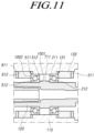
- FIGS. 7 to 11 are cross-sectional views illustrating a steer-by-wire steering device according to the present embodiments.
- first element is connected or coupled to”, “contacts or overlaps” etc. a second element
- first element is connected or coupled to” or “directly contact or overlap” the second element
- a third element can also be “interposed” between the first and second elements, or the first and second elements can “be connected or coupled to”, “contact or overlap”, etc. each other via a fourth element.
- the second element may be included in at least one of two or more elements that “are connected or coupled to”, “contact or overlap”, etc. each other.
- time relative terms such as “after,” “subsequent to,” “next,” “before,” and the like, are used to describe processes or operations of elements or configurations, or flows or steps in operating, processing, manufacturing methods, these terms may be used to describe non-consecutive or non-sequential processes or operations unless the term “directly” or “immediately” is used together.
- FIG. 1 is a cross-sectional view illustrating a steer-by-wire steering device according to the present embodiments.
- FIGS. 2 to 6 are cross-sectional views illustrating a steer-by-wire steering device according to the present embodiments.
- FIGS. 7 to 11 are cross-sectional views illustrating a steer-by-wire steering device according to the present embodiments.
- the steer-by-wire steering device 100 includes a steering shaft 120 and a housing 110 receiving the steering shaft 120 and, as is described below in detail, increases the driver's steering feeling by applying pre-load to a first bearing 131 and a second bearing 511 , coupled between the steering shaft 120 and the housing 110 to support rotation of the steering shaft 120 , to generate friction.
- first bearing 131 and the second bearing 511 are coupled to the lower column 121 of the steering shaft 120 , this is exemplary. Although the first bearing 131 and the second bearing 511 are coupled to the upper column 122 , it is possible to generate friction by applying pre-load.
- one axial side refers to the left side on the drawings, and the other axial side refers to the right side on the drawings.
- the one axial side is a direction to the steering wheel, and the other axial side is the opposite direction, vice versa is also possible without limited thereto.
- a steer-by-wire steering device 100 includes a housing 110 receiving a steering shaft 120 and having a first step 132 formed on an inner circumferential surface thereof as a diameter thereof is reduced, a first bearing 131 including a first outer ring 211 having a first axial side surface supported on the first step 132 and a first inner ring 212 coupled to an outer circumferential surface of the steering shaft 120 , and a first coupling member 133 coupled to the outer circumferential surface of the steering shaft 120 to pressurize the second axial side surface of the first inner ring 212 .
- the first bearing 131 is coupled between the inner circumferential surface of the housing 110 and the outer circumferential surface of the steering shaft 120 to support rotation of the steering shaft 120 .
- the first step 132 is formed on the inner circumferential surface of the housing 110 as the diameter is decreased, and the first coupling member 133 is coupled to the outer circumferential surface of the steering shaft 120 so that the first bearing 131 is axially fixed between the first step 132 and the first coupling member 133 .
- the first bearing 131 is axially inserted on the inner circumferential surface of the housing 110 so that the first outer ring 211 is axially supported on the first step 132 , and the first coupling member 133 coupled to the outer circumferential surface of the steering shaft 120 is axially supported on the first inner ring 212 on the opposite side of the first step 132 to fix the first bearing 131 .
- the first coupling member 133 is press-fitted or screwed on the outer circumferential surface of the steering shaft 120 . As the first coupling member 133 is fitted over the steering shaft 120 to axially pressurize the first inner ring 212 , pre-load is applied to the first bearing 131 , increasing friction caused inside the first bearing 131 during rotation and hence increasing the driver's steering feeling.
- the first bearing 131 may be an angular ball bearing. As shown in the drawings, as the first outer ring 211 is supported by the balls on the first axial side, and the first inner ring 212 is supported by the balls on the second axial side, and the first coupling member 133 axially pressurizes the first inner ring 212 , friction on the contact surface between the balls and the first outer ring 211 and the contact surface between the balls and the first inner ring 212 increases.
- a first anti-loosening member 311 supported by the first coupling member 133 on the second axial side is coupled to the outer circumferential surface of the steering shaft 120 .
- the first anti-loosening member 311 supports the first coupling member 133 in the direction to the first step 132 and prevents the coupling between the first coupling member 133 and the steering shaft 120 from loosening, maintaining the friction inside the first bearing 131 constant.
- the first anti-loosening member 311 may be press-fitted and screwed to the steering shaft 120 .
- the first coupling member 133 and the first anti-loosening member 311 are screwed to the steering shaft 120
- the first coupling member 133 is first screwed to the steering shaft 120 to pressurize the first bearing 131 , and the first anti-loosening member 311 is then screwed to the steering shaft 120 to thereby prevent the first coupling member 133 from loosening.
- the first coupling member 133 may be screwed by a tightening torque of 5 to 25 Nm
- the first anti-loosening member 311 may be screwed by a tightening torque of 48 to 69 Nm.
- the portion of the steering shaft 120 , coupled with the first coupling member 133 may be formed to have a smaller outer diameter than the portion coupled with the first inner ring 212 .
- the first inner ring 212 is coupled to the portion formed with a relatively large outer diameter
- the first coupling member 133 is coupled to the portion formed with a relatively small outer diameter
- the first coupling member 133 For the first coupling member 133 to be coupled to pressurize the first inner ring 212 , the first coupling member 133 should not be axially supported by the first outer ring 211 . As the first coupling member 133 is coupled to the portion with a relatively small outer diameter, it may be prevented from being supported on the first outer ring 211 . Further, although the first coupling member 133 has a larger radial thickness, it is not supported on the first outer ring 211 , so that the first coupling member 133 may be screwed with high tightening torque.
- a second bearing 511 may further be provided between the steering shaft 120 and the housing 110 , supporting rotation of the steering shaft 120 .
- a second step 521 is formed on the inner circumferential surface of the housing 110 as the diameter is increased on the second axial side of the first step 132 (in other words, a diameter-reduced portion is formed on the inner circumferential surface of the housing 110 , and the first step 132 and the second step 521 are provided on two opposite sides of the diameter-reduced portion), and the second bearing 511 includes a second outer ring 512 coupled to the inner circumferential surface of the housing and having the second axial side supported on the second step 521 and a second inner ring 513 coupled to the outer circumferential surface of the steering shaft 120 .
- the second bearing 511 is positioned on the first axial side of the first bearing 131 . As described below, as is done on the first bearing 131 , pre-load is applied to the second bearing 511 to create friction, thereby increasing the driver's steering feeling.
- the friction caused inside the bearings and the pre-load applied to each bearing may be distributed to increase the driver's steering feeling, thus rendering it possible to prevent damage to the balls and minimize debris due to wear.
- the second bearing 511 may be an angular ball bearing. As shown in the drawings, the second outer ring 512 is supported by the balls on the second axial side, and the second inner ring 513 is supported by the balls on the first axial side.
- first bearing 131 and the second bearing 511 are back-to-back coupled to each other.
- a third step 531 supported on the first axial side surface of the second inner ring 513 is formed on the outer circumferential surface of the steering shaft 120 as the diameter is increased, and the second bearing 511 is axially fixed between the second step 521 and the third step 531 .
- the first coupling member 133 is coupled to the steering shaft 120 while pressurizing the first inner ring 212 , pre-load is applied to the second bearing 511 as well, so that the driver's steering feeling may be increased by the friction caused inside the first bearing 131 and the second bearing 511 .
- a second coupling member 611 to pressurize the first axial side of the second inner ring 513 is coupled to the outer circumferential surface of the steering shaft 120 , so that the driver's steering feeling may be increased by the friction caused inside the first bearing 131 by the first coupling member 133 and the friction caused inside the second bearing 511 by the second coupling member 611 .
- the second coupling member 611 may be prevented from loosening.
- the second coupling member 611 and the second anti-loosening member 612 may be press-fitted or screwed to the steering shaft 120 , and details thereof are the same as those of the first coupling member 133 and the second anti-loosening member 612 and are thus omitted from description.
- portion of the steering shaft 120 , coupled with the second coupling member 611 may be formed to have a smaller outer diameter than the portion coupled with the second inner ring 513 .
- a steer-by-wire steering device 100 includes a housing 110 receiving a steering shaft 120 having a first step 711 formed on an outer circumferential surface thereof as the diameter is increased, a first bearing 131 including a first inner ring 212 having a first axial side surface supported on the first step 711 and a first outer ring 211 coupled to the inner circumferential surface of the housing 110 and a first coupling member 133 coupled to the inner circumferential surface of the housing 110 to pressurize a second axial side surface of the first outer ring 211 .
- the first step 711 is formed on the outer circumferential surface of the steering shaft 120 as the diameter is increased, and the first coupling member 133 is coupled to the inner circumferential surface of the housing 110 so that the first bearing 131 is axially fixed between the first step 711 and the first coupling member 133 and supports rotation of the steering shaft 120 .
- first bearing 131 may be an angular ball bearing. As shown in the drawings, the first inner ring 212 is supported by the balls on the first axial side, and the first outer ring 211 is supported by the balls on the second axial side so that the first coupling member 133 axially pressurizes the first outer ring 211 , causing friction inside the first bearing 131 and hence increasing the driver's steering feeling.
- a first anti-loosening member 311 supported by the first coupling member 133 on the second axial side is coupled to the inner circumferential surface of the housing 110 , preventing the coupling between the first coupling member 133 and the steering shaft 120 from loosening and keeping the friction caused inside the first bearing 131 constant.
- the first coupling member 133 and the first anti-loosening member 311 may be press-fitted or screwed to the housing 110 and, as appropriate tightening torque is selected, it is possible to increase the range of adjusting the frictional force applied to the steering shaft 120 and keep the frictional force constant.
- the portion of the housing 110 , coupled with the first coupling member 133 may be formed to have a larger inner diameter than the portion coupled with the first outer ring 211 .
- a second bearing 511 may further be provided between the steering shaft 120 and the housing 110 , supporting rotation of the steering shaft 120 .
- a second step 1001 is formed on the outer circumferential surface of the steering shaft 120 , on the second axial side of the first step 711 , as the diameter is decreased, and the second bearing 511 is coupled to the outer circumferential surface of the steering shaft 120 and includes a second inner ring 513 having the second axial side surface supported on the second step 1001 and a second outer ring 512 coupled to the inner circumferential surface of the housing 110 .
- the second bearing 511 is positioned on the first axial side of the first bearing 131 .
- the second bearing 511 may be an angular ball bearing. As shown in the drawings, the second inner ring 513 is supported by the balls on the second axial side, and the second outer ring 512 is supported by the balls on the first axial side.
- first bearing 131 and the second bearing 511 are face-to-face coupled to each other.
- a third step 1002 supported on the first axial side surface of the second outer ring 512 is formed on the inner circumferential surface of the housing 110 as the diameter is decreased, and the second bearing 511 is axially fixed between the second step 1001 and the third step 1002 .
- the first coupling member 133 is coupled to the housing 110 while pressurizing the first outer ring 211 , pre-load is applied to the second bearing 511 as well, so that the driver's steering feeling may be increased by the friction caused inside the first bearing 131 and the second bearing 511 .
- a second coupling member 611 to pressurize the first axial side surface of the second outer ring 512 is coupled to the inner circumferential surface of the housing 110 , so that the driver's steering feeling may be increased by the friction caused inside the first bearing 131 and the second bearing 511 by the first coupling member 133 and the second coupling member 611 , respectively.
- a second anti-loosening member 612 supported by the second coupling member 611 on the first axial side is coupled to the inner circumferential surface of the housing 110 , preventing the second coupling member 611 from loosening.
- the second coupling member 611 and the second anti-loosening member 612 may be press-fitted or screwed to the housing 110 .
- portion of the housing 110 coupled with the second coupling member 611 , is formed to have a larger inner diameter than the portion coupled with the second outer ring 512 , so that the second coupling member 611 may be prevented from being axially supported on the second inner ring 513 and be screwed with higher tightening torque.
- so-shaped steer-by-wire steering device it is possible to impart a better steering feeling to the driver by increasing the range of adjusting friction on the steering shaft and keeping the adjusted friction constant while saving components to enhance assemblability and save costs, and preventing deformation of the steering shaft.
Landscapes
- Engineering & Computer Science (AREA)
- General Engineering & Computer Science (AREA)
- Mechanical Engineering (AREA)
- Chemical & Material Sciences (AREA)
- Combustion & Propulsion (AREA)
- Transportation (AREA)
- Power Steering Mechanism (AREA)
- Steering Controls (AREA)
- Steering Control In Accordance With Driving Conditions (AREA)
Abstract
Description
Claims (20)
Applications Claiming Priority (3)
| Application Number | Priority Date | Filing Date | Title |
|---|---|---|---|
| KR1020190137576A KR102878983B1 (en) | 2019-10-31 | 2019-10-31 | Steer-by-wire type steering apparatus |
| KR10-2019-0137576 | 2019-10-31 | ||
| PCT/KR2020/014437 WO2021085928A1 (en) | 2019-10-31 | 2020-10-21 | Steer-by-wire steering apparatus |
Publications (2)
| Publication Number | Publication Date |
|---|---|
| US20240140520A1 US20240140520A1 (en) | 2024-05-02 |
| US12151748B2 true US12151748B2 (en) | 2024-11-26 |
Family
ID=75714614
Family Applications (1)
| Application Number | Title | Priority Date | Filing Date |
|---|---|---|---|
| US17/769,345 Active 2040-10-21 US12151748B2 (en) | 2019-10-31 | 2020-10-21 | Steer-by-wire steering apparatus |
Country Status (5)
| Country | Link |
|---|---|
| US (1) | US12151748B2 (en) |
| KR (1) | KR102878983B1 (en) |
| CN (1) | CN114616162A (en) |
| DE (1) | DE112020005376T5 (en) |
| WO (1) | WO2021085928A1 (en) |
Citations (35)
| Publication number | Priority date | Publication date | Assignee | Title |
|---|---|---|---|---|
| US610961A (en) * | 1898-09-20 | Preston davies | ||
| US1219921A (en) * | 1915-06-11 | 1917-03-20 | Auburn Ball Bearing Company | Ball-bearing. |
| US1433014A (en) * | 1921-01-26 | 1922-10-24 | Samuel S Stewart | Compound ball bearing |
| US3030158A (en) * | 1957-12-21 | 1962-04-17 | Rothe Erde Eisenwerk | Single- and multi-row wire bearing systems |
| EP0739807A2 (en) * | 1995-04-28 | 1996-10-30 | Trw Inc. | Power steering system |
| KR20010095519A (en) | 2000-04-10 | 2001-11-07 | 밍 루 | Steering auxiliary apparatus for wire steering system |
| JP2002346807A (en) | 2001-05-25 | 2002-12-04 | Mitsubishi Heavy Ind Ltd | Main-shaft equipment |
| US20020189888A1 (en) | 2001-06-19 | 2002-12-19 | Magnus Brian J. | Steer-by wire handwheel actuator |
| US20030021507A1 (en) * | 2001-07-26 | 2003-01-30 | Trw Inc. | Steering column with bearings |
| JP2007186014A (en) | 2006-01-11 | 2007-07-26 | Toyota Motor Corp | Vehicle steering system |
| US7637667B1 (en) * | 2007-07-05 | 2009-12-29 | Kilian Manufacturing Corp. | Bearing assembly for a steering assembly |
| US20100108430A1 (en) * | 2008-11-04 | 2010-05-06 | Kayaba Industry Co., Ltd. | Power steering device |
| US20110303480A1 (en) | 2010-06-11 | 2011-12-15 | Honda Motor Co., Ltd. | Electric power steering apparatus |
| CN102425598A (en) * | 2011-11-06 | 2012-04-25 | 湖北新火炬科技股份有限公司 | Heavy load long life hub bearing unit |
| JP2012091677A (en) | 2010-10-27 | 2012-05-17 | Jtekt Corp | Vehicle steering device |
| JP2012144108A (en) | 2011-01-11 | 2012-08-02 | Nsk Ltd | Steering device |
| JP2014040210A (en) | 2012-08-23 | 2014-03-06 | Nsk Ltd | Steering system |
| US20140116780A1 (en) * | 2012-10-25 | 2014-05-01 | Scientific Drilling International, Inc. | Hybrid Bearings for Downhole Motors |
| CN105387076A (en) | 2014-08-29 | 2016-03-09 | 斯凯孚公司 | Rolling bearing |
| JP2017124714A (en) | 2016-01-13 | 2017-07-20 | 株式会社ショーワ | Steering gear |
| JP2017128250A (en) * | 2016-01-21 | 2017-07-27 | 株式会社ショーワ | Steering force adjusting device and steering device |
| DE102016211556A1 (en) * | 2016-06-28 | 2017-12-28 | Schaeffler Technologies AG & Co. KG | Tolerance ring for a steering shaft of a motor vehicle |
| US20180031034A1 (en) * | 2016-07-27 | 2018-02-01 | Jtekt Corporation | Combination bearing |
| DE102016221078A1 (en) * | 2016-10-26 | 2018-04-26 | Thyssenkrupp Ag | Steering column for a motor vehicle |
| CN108518413A (en) * | 2018-06-05 | 2018-09-11 | 中国航发哈尔滨轴承有限公司 | A kind of double semi outer rings double-row angular contact bal bearing |
| US20190178291A1 (en) * | 2016-07-29 | 2019-06-13 | Nsk Ltd. | Ball bearing |
| US20200164910A1 (en) * | 2017-06-14 | 2020-05-28 | Yamada Manufacturing Co., Ltd. | Steering device |
| CN112283242A (en) * | 2020-09-30 | 2021-01-29 | 人本股份有限公司 | hub unit bearing |
| DE102020210667A1 (en) * | 2019-09-18 | 2021-03-18 | Aktiebolaget Skf | Rolling bearings, in particular hybrid rolling bearings for a refrigerant compressor |
| US20220227413A1 (en) * | 2021-01-19 | 2022-07-21 | Zf Automotive Germany Gmbh | Steer-by-wire steering apparatus and method for operating a steer-by-wire steering apparatus |
| US20230015798A1 (en) * | 2021-07-19 | 2023-01-19 | Mando Corporation | Steering control device and method |
| US20230109811A1 (en) * | 2021-10-13 | 2023-04-13 | Zf Automotive Germany Gmbh | Rotation limitation module and steering wheel module for a steer-by-wire steering system |
| US20230132966A1 (en) * | 2021-11-02 | 2023-05-04 | Zf Automotive Germany Gmbh | Rotation limitation module and steering wheel module for a steer-by-wire steering system |
| US20230135320A1 (en) * | 2021-11-02 | 2023-05-04 | Zf Automotive Germany Gmbh | Rotation-limiting assembly and steering wheel assembly for a steer-by-wire steering system |
| US20230141259A1 (en) * | 2021-11-10 | 2023-05-11 | Zf Automotive Germany Gmbh | Steering apparatus with a blocking device for limiting a steering angle of rotation, and steer-by-wire steering system with such a steering apparatus |
Family Cites Families (1)
| Publication number | Priority date | Publication date | Assignee | Title |
|---|---|---|---|---|
| KR20190137576A (en) | 2018-06-02 | 2019-12-11 | 이원도 | Risk, caution display through one color touching screen on subway screen door |
-
2019
- 2019-10-31 KR KR1020190137576A patent/KR102878983B1/en active Active
-
2020
- 2020-10-21 CN CN202080073706.4A patent/CN114616162A/en active Pending
- 2020-10-21 WO PCT/KR2020/014437 patent/WO2021085928A1/en not_active Ceased
- 2020-10-21 US US17/769,345 patent/US12151748B2/en active Active
- 2020-10-21 DE DE112020005376.8T patent/DE112020005376T5/en active Pending
Patent Citations (43)
| Publication number | Priority date | Publication date | Assignee | Title |
|---|---|---|---|---|
| US610961A (en) * | 1898-09-20 | Preston davies | ||
| US1219921A (en) * | 1915-06-11 | 1917-03-20 | Auburn Ball Bearing Company | Ball-bearing. |
| US1433014A (en) * | 1921-01-26 | 1922-10-24 | Samuel S Stewart | Compound ball bearing |
| US3030158A (en) * | 1957-12-21 | 1962-04-17 | Rothe Erde Eisenwerk | Single- and multi-row wire bearing systems |
| EP0739807A2 (en) * | 1995-04-28 | 1996-10-30 | Trw Inc. | Power steering system |
| KR20010095519A (en) | 2000-04-10 | 2001-11-07 | 밍 루 | Steering auxiliary apparatus for wire steering system |
| JP2002346807A (en) | 2001-05-25 | 2002-12-04 | Mitsubishi Heavy Ind Ltd | Main-shaft equipment |
| US20020189888A1 (en) | 2001-06-19 | 2002-12-19 | Magnus Brian J. | Steer-by wire handwheel actuator |
| US20030021507A1 (en) * | 2001-07-26 | 2003-01-30 | Trw Inc. | Steering column with bearings |
| US6513984B1 (en) * | 2001-07-26 | 2003-02-04 | Trw Inc. | Steering column with bearings |
| JP2007186014A (en) | 2006-01-11 | 2007-07-26 | Toyota Motor Corp | Vehicle steering system |
| US7637667B1 (en) * | 2007-07-05 | 2009-12-29 | Kilian Manufacturing Corp. | Bearing assembly for a steering assembly |
| US20100108430A1 (en) * | 2008-11-04 | 2010-05-06 | Kayaba Industry Co., Ltd. | Power steering device |
| US8118328B2 (en) * | 2008-11-04 | 2012-02-21 | Kayaba Industry Co., Ltd. | Power steering device |
| US20110303480A1 (en) | 2010-06-11 | 2011-12-15 | Honda Motor Co., Ltd. | Electric power steering apparatus |
| JP2012091677A (en) | 2010-10-27 | 2012-05-17 | Jtekt Corp | Vehicle steering device |
| JP2012144108A (en) | 2011-01-11 | 2012-08-02 | Nsk Ltd | Steering device |
| CN102425598A (en) * | 2011-11-06 | 2012-04-25 | 湖北新火炬科技股份有限公司 | Heavy load long life hub bearing unit |
| JP2014040210A (en) | 2012-08-23 | 2014-03-06 | Nsk Ltd | Steering system |
| US9045941B2 (en) * | 2012-10-25 | 2015-06-02 | Scientific Drilling International, Inc. | Hybrid bearings for downhole motors |
| US20140116780A1 (en) * | 2012-10-25 | 2014-05-01 | Scientific Drilling International, Inc. | Hybrid Bearings for Downhole Motors |
| CN105387076A (en) | 2014-08-29 | 2016-03-09 | 斯凯孚公司 | Rolling bearing |
| JP2017124714A (en) | 2016-01-13 | 2017-07-20 | 株式会社ショーワ | Steering gear |
| JP2017128250A (en) * | 2016-01-21 | 2017-07-27 | 株式会社ショーワ | Steering force adjusting device and steering device |
| DE102016211556A1 (en) * | 2016-06-28 | 2017-12-28 | Schaeffler Technologies AG & Co. KG | Tolerance ring for a steering shaft of a motor vehicle |
| US20180031034A1 (en) * | 2016-07-27 | 2018-02-01 | Jtekt Corporation | Combination bearing |
| US10145413B2 (en) * | 2016-07-27 | 2018-12-04 | Jtekt Corporation | Combination bearing |
| US20190178291A1 (en) * | 2016-07-29 | 2019-06-13 | Nsk Ltd. | Ball bearing |
| DE102016221078A1 (en) * | 2016-10-26 | 2018-04-26 | Thyssenkrupp Ag | Steering column for a motor vehicle |
| US20200164910A1 (en) * | 2017-06-14 | 2020-05-28 | Yamada Manufacturing Co., Ltd. | Steering device |
| US11643130B2 (en) * | 2017-06-14 | 2023-05-09 | Yamada Manufacturing Co., Ltd. | Steering device |
| US20220001913A1 (en) * | 2017-06-14 | 2022-01-06 | Yamada Manufacturing Co., Ltd. | Steering device |
| CN108518413A (en) * | 2018-06-05 | 2018-09-11 | 中国航发哈尔滨轴承有限公司 | A kind of double semi outer rings double-row angular contact bal bearing |
| DE102020210667A1 (en) * | 2019-09-18 | 2021-03-18 | Aktiebolaget Skf | Rolling bearings, in particular hybrid rolling bearings for a refrigerant compressor |
| CN112283242A (en) * | 2020-09-30 | 2021-01-29 | 人本股份有限公司 | hub unit bearing |
| US20220227413A1 (en) * | 2021-01-19 | 2022-07-21 | Zf Automotive Germany Gmbh | Steer-by-wire steering apparatus and method for operating a steer-by-wire steering apparatus |
| US20230015798A1 (en) * | 2021-07-19 | 2023-01-19 | Mando Corporation | Steering control device and method |
| US20230109811A1 (en) * | 2021-10-13 | 2023-04-13 | Zf Automotive Germany Gmbh | Rotation limitation module and steering wheel module for a steer-by-wire steering system |
| US20230132966A1 (en) * | 2021-11-02 | 2023-05-04 | Zf Automotive Germany Gmbh | Rotation limitation module and steering wheel module for a steer-by-wire steering system |
| US20230135320A1 (en) * | 2021-11-02 | 2023-05-04 | Zf Automotive Germany Gmbh | Rotation-limiting assembly and steering wheel assembly for a steer-by-wire steering system |
| US11772701B2 (en) * | 2021-11-02 | 2023-10-03 | F Automotive Germany GmbH | Rotation limitation module and steering wheel module for a steer-by-wire steering system |
| US20230141259A1 (en) * | 2021-11-10 | 2023-05-11 | Zf Automotive Germany Gmbh | Steering apparatus with a blocking device for limiting a steering angle of rotation, and steer-by-wire steering system with such a steering apparatus |
| US11866103B2 (en) * | 2021-11-10 | 2024-01-09 | Zf Automotive Germany Gmbh | Steering apparatus with a blocking device for limiting a steering angle of rotation, and steer-by-wire steering system with such a steering apparatus |
Non-Patent Citations (3)
| Title |
|---|
| JP2007186014A machine translation from espacenet.com (Year: 2024). * |
| JP2012144108A machine translation from espacenet.com (Year: 2024). * |
| Office Action issued in Chinese Patent Application No. 202080073706.4 dated Dec. 13, 2023. |
Also Published As
| Publication number | Publication date |
|---|---|
| US20240140520A1 (en) | 2024-05-02 |
| DE112020005376T5 (en) | 2022-09-08 |
| CN114616162A (en) | 2022-06-10 |
| KR20210051818A (en) | 2021-05-10 |
| KR102878983B1 (en) | 2025-10-30 |
| WO2021085928A1 (en) | 2021-05-06 |
Similar Documents
| Publication | Publication Date | Title |
|---|---|---|
| US12319364B2 (en) | Steer-by-wire steering apparatus | |
| US6186268B1 (en) | Electric power steering unit | |
| US12037056B2 (en) | Steer-by-wire type steering apparatus | |
| US11505239B2 (en) | Steering system and method for manufacturing steering system | |
| US9963165B2 (en) | Ball nut assembly for a rack electrical power assist steering system | |
| US12151748B2 (en) | Steer-by-wire steering apparatus | |
| JP2001315653A (en) | Electric power steering system | |
| JP5941322B2 (en) | Vehicle steering device | |
| US11767052B2 (en) | Steering device of vehicle | |
| US20220250672A1 (en) | Motor assembly and steering apparatus for vehicle having the same | |
| US20220063706A1 (en) | Steer-by-wire steering device | |
| US12151749B2 (en) | Steering system for steer-by-wire | |
| WO2007069575A1 (en) | Steering device | |
| US7575091B2 (en) | Electric power steering apparatus | |
| JP2003097661A (en) | Ball screw and wheel steering system using it | |
| US20150329139A1 (en) | Electric power steering apparatus | |
| JP2004211774A (en) | Bearing device for handle column | |
| JP2015143069A (en) | electric power steering device | |
| US20220410963A1 (en) | Steer-by-wire steering apparatus | |
| US20220242476A1 (en) | Rack-driven power assisted steering device | |
| US20220204073A1 (en) | Steer-by-wire type steering apparatus | |
| US11447171B2 (en) | Steering device of vehicle | |
| WO2007037499A1 (en) | Electric power steering system | |
| JP5370201B2 (en) | Universal joint yoke | |
| JP2010187492A (en) | Motor and electric power steering device |
Legal Events
| Date | Code | Title | Description |
|---|---|---|---|
| AS | Assignment |
Owner name: MANDO CORPORATION, KOREA, REPUBLIC OF Free format text: ASSIGNMENT OF ASSIGNORS INTEREST;ASSIGNORS:KIM, JEONG RAE;JUNG, EUL GO;REEL/FRAME:059606/0432 Effective date: 20220412 |
|
| FEPP | Fee payment procedure |
Free format text: ENTITY STATUS SET TO UNDISCOUNTED (ORIGINAL EVENT CODE: BIG.); ENTITY STATUS OF PATENT OWNER: LARGE ENTITY |
|
| AS | Assignment |
Owner name: HL MANDO CORPORATION, KOREA, REPUBLIC OF Free format text: CHANGE OF NAME;ASSIGNOR:MANDO CORPORATION;REEL/FRAME:062202/0001 Effective date: 20220908 |
|
| STPP | Information on status: patent application and granting procedure in general |
Free format text: NON FINAL ACTION MAILED |
|
| STPP | Information on status: patent application and granting procedure in general |
Free format text: RESPONSE TO NON-FINAL OFFICE ACTION ENTERED AND FORWARDED TO EXAMINER |
|
| STPP | Information on status: patent application and granting procedure in general |
Free format text: NOTICE OF ALLOWANCE MAILED -- APPLICATION RECEIVED IN OFFICE OF PUBLICATIONS |
|
| STCF | Information on status: patent grant |
Free format text: PATENTED CASE |