US12150545B2 - Brushing part and method for manufacturing the brushing part - Google Patents
Brushing part and method for manufacturing the brushing part Download PDFInfo
- Publication number
- US12150545B2 US12150545B2 US17/632,206 US202017632206A US12150545B2 US 12150545 B2 US12150545 B2 US 12150545B2 US 202017632206 A US202017632206 A US 202017632206A US 12150545 B2 US12150545 B2 US 12150545B2
- Authority
- US
- United States
- Prior art keywords
- hole
- tuft
- brushing
- mouth guard
- support
- Prior art date
- Legal status (The legal status is an assumption and is not a legal conclusion. Google has not performed a legal analysis and makes no representation as to the accuracy of the status listed.)
- Active, expires
Links
- 230000001680 brushing effect Effects 0.000 title claims abstract description 102
- 238000000034 method Methods 0.000 title claims abstract description 37
- 238000004519 manufacturing process Methods 0.000 title claims abstract description 25
- 238000000151 deposition Methods 0.000 claims abstract description 15
- 238000005553 drilling Methods 0.000 claims description 30
- 210000004513 dentition Anatomy 0.000 claims description 24
- 230000036346 tooth eruption Effects 0.000 claims description 24
- 239000000853 adhesive Substances 0.000 claims description 20
- 230000001070 adhesive effect Effects 0.000 claims description 20
- 238000000465 moulding Methods 0.000 claims description 15
- 238000003780 insertion Methods 0.000 claims description 10
- 230000037431 insertion Effects 0.000 claims description 10
- 230000015572 biosynthetic process Effects 0.000 claims description 5
- 239000011347 resin Substances 0.000 abstract description 5
- 229920005989 resin Polymers 0.000 abstract description 5
- 239000003292 glue Substances 0.000 abstract 1
- 239000000463 material Substances 0.000 description 10
- 229920002457 flexible plastic Polymers 0.000 description 4
- -1 Styrene-Ethylene-Butylene-Styrene Chemical class 0.000 description 3
- 238000004140 cleaning Methods 0.000 description 2
- 238000009826 distribution Methods 0.000 description 2
- 230000000694 effects Effects 0.000 description 2
- 229920001707 polybutylene terephthalate Polymers 0.000 description 2
- 238000006116 polymerization reaction Methods 0.000 description 2
- 235000001674 Agaricus brunnescens Nutrition 0.000 description 1
- 239000004677 Nylon Substances 0.000 description 1
- 230000001419 dependent effect Effects 0.000 description 1
- 230000004927 fusion Effects 0.000 description 1
- 238000010438 heat treatment Methods 0.000 description 1
- 230000014759 maintenance of location Effects 0.000 description 1
- 229920001778 nylon Polymers 0.000 description 1
- 229920001296 polysiloxane Polymers 0.000 description 1
- 238000002360 preparation method Methods 0.000 description 1
- 239000000126 substance Substances 0.000 description 1
- 229920001169 thermoplastic Polymers 0.000 description 1
- 229920002725 thermoplastic elastomer Polymers 0.000 description 1
- 239000004416 thermosoftening plastic Substances 0.000 description 1
Images


Classifications
-
- A—HUMAN NECESSITIES
- A46—BRUSHWARE
- A46D—MANUFACTURE OF BRUSHES
- A46D3/00—Preparing, i.e. Manufacturing brush bodies
- A46D3/06—Machines for both drilling bodies and inserting bristles
-
- A—HUMAN NECESSITIES
- A46—BRUSHWARE
- A46B—BRUSHES
- A46B13/00—Brushes with driven brush bodies or carriers
- A46B13/02—Brushes with driven brush bodies or carriers power-driven carriers
- A46B13/023—Brushes with driven brush bodies or carriers power-driven carriers with means for inducing vibration to the bristles
-
- A—HUMAN NECESSITIES
- A46—BRUSHWARE
- A46B—BRUSHES
- A46B3/00—Brushes characterised by the way in which the bristles are fixed or joined in or on the brush body or carrier
- A46B3/02—Brushes characterised by the way in which the bristles are fixed or joined in or on the brush body or carrier by pitch, resin, cement, or other adhesives
-
- A—HUMAN NECESSITIES
- A46—BRUSHWARE
- A46B—BRUSHES
- A46B3/00—Brushes characterised by the way in which the bristles are fixed or joined in or on the brush body or carrier
- A46B3/04—Brushes characterised by the way in which the bristles are fixed or joined in or on the brush body or carrier by mouldable materials, e.g. metals, cellulose derivatives, plastics
-
- A—HUMAN NECESSITIES
- A46—BRUSHWARE
- A46B—BRUSHES
- A46B3/00—Brushes characterised by the way in which the bristles are fixed or joined in or on the brush body or carrier
- A46B3/06—Brushes characterised by the way in which the bristles are fixed or joined in or on the brush body or carrier by welding together bristles made of metal wires or plastic materials
-
- A—HUMAN NECESSITIES
- A46—BRUSHWARE
- A46B—BRUSHES
- A46B5/00—Brush bodies; Handles integral with brushware
- A46B5/02—Brush bodies; Handles integral with brushware specially shaped for holding by the hand
-
- A—HUMAN NECESSITIES
- A46—BRUSHWARE
- A46B—BRUSHES
- A46B9/00—Arrangements of the bristles in the brush body
- A46B9/02—Position or arrangement of bristles in relation to surface of the brush body, e.g. inclined, in rows, in groups
- A46B9/04—Arranged like in or for toothbrushes
- A46B9/045—Arranged like in or for toothbrushes specially adapted for cleaning a plurality of tooth surfaces simultaneously
-
- A—HUMAN NECESSITIES
- A46—BRUSHWARE
- A46D—MANUFACTURE OF BRUSHES
- A46D3/00—Preparing, i.e. Manufacturing brush bodies
-
- A—HUMAN NECESSITIES
- A46—BRUSHWARE
- A46D—MANUFACTURE OF BRUSHES
- A46D3/00—Preparing, i.e. Manufacturing brush bodies
- A46D3/005—Preparing, i.e. Manufacturing brush bodies by moulding or casting a body around bristles or tufts of bristles
-
- A—HUMAN NECESSITIES
- A46—BRUSHWARE
- A46D—MANUFACTURE OF BRUSHES
- A46D3/00—Preparing, i.e. Manufacturing brush bodies
- A46D3/02—Machines for drilling bodies
-
- A—HUMAN NECESSITIES
- A46—BRUSHWARE
- A46D—MANUFACTURE OF BRUSHES
- A46D3/00—Preparing, i.e. Manufacturing brush bodies
- A46D3/04—Machines for inserting or fixing bristles in bodies
- A46D3/045—Machines for inserting or fixing bristles in bodies for fixing bristles by fusing or gluing to a body
-
- A—HUMAN NECESSITIES
- A46—BRUSHWARE
- A46D—MANUFACTURE OF BRUSHES
- A46D3/00—Preparing, i.e. Manufacturing brush bodies
- A46D3/08—Parts of brush-making machines
-
- A—HUMAN NECESSITIES
- A61—MEDICAL OR VETERINARY SCIENCE; HYGIENE
- A61C—DENTISTRY; APPARATUS OR METHODS FOR ORAL OR DENTAL HYGIENE
- A61C17/00—Devices for cleaning, polishing, rinsing or drying teeth, teeth cavities or prostheses; Saliva removers; Dental appliances for receiving spittle
- A61C17/16—Power-driven cleaning or polishing devices
- A61C17/22—Power-driven cleaning or polishing devices with brushes, cushions, cups, or the like
- A61C17/222—Brush body details, e.g. the shape thereof or connection to handle
-
- A—HUMAN NECESSITIES
- A61—MEDICAL OR VETERINARY SCIENCE; HYGIENE
- A61C—DENTISTRY; APPARATUS OR METHODS FOR ORAL OR DENTAL HYGIENE
- A61C17/00—Devices for cleaning, polishing, rinsing or drying teeth, teeth cavities or prostheses; Saliva removers; Dental appliances for receiving spittle
- A61C17/16—Power-driven cleaning or polishing devices
- A61C17/22—Power-driven cleaning or polishing devices with brushes, cushions, cups, or the like
- A61C17/225—Handles or details thereof
-
- A—HUMAN NECESSITIES
- A61—MEDICAL OR VETERINARY SCIENCE; HYGIENE
- A61C—DENTISTRY; APPARATUS OR METHODS FOR ORAL OR DENTAL HYGIENE
- A61C17/00—Devices for cleaning, polishing, rinsing or drying teeth, teeth cavities or prostheses; Saliva removers; Dental appliances for receiving spittle
- A61C17/16—Power-driven cleaning or polishing devices
- A61C17/22—Power-driven cleaning or polishing devices with brushes, cushions, cups, or the like
- A61C17/228—Self-contained intraoral toothbrush, e.g. mouth-guard toothbrush without handle
-
- A—HUMAN NECESSITIES
- A61—MEDICAL OR VETERINARY SCIENCE; HYGIENE
- A61C—DENTISTRY; APPARATUS OR METHODS FOR ORAL OR DENTAL HYGIENE
- A61C17/00—Devices for cleaning, polishing, rinsing or drying teeth, teeth cavities or prostheses; Saliva removers; Dental appliances for receiving spittle
- A61C17/16—Power-driven cleaning or polishing devices
- A61C17/22—Power-driven cleaning or polishing devices with brushes, cushions, cups, or the like
- A61C17/32—Power-driven cleaning or polishing devices with brushes, cushions, cups, or the like reciprocating or oscillating
- A61C17/34—Power-driven cleaning or polishing devices with brushes, cushions, cups, or the like reciprocating or oscillating driven by electric motor
- A61C17/3409—Power-driven cleaning or polishing devices with brushes, cushions, cups, or the like reciprocating or oscillating driven by electric motor characterized by the movement of the brush body
- A61C17/3481—Vibrating brush body, e.g. by using eccentric weights
-
- B—PERFORMING OPERATIONS; TRANSPORTING
- B29—WORKING OF PLASTICS; WORKING OF SUBSTANCES IN A PLASTIC STATE IN GENERAL
- B29C—SHAPING OR JOINING OF PLASTICS; SHAPING OF MATERIAL IN A PLASTIC STATE, NOT OTHERWISE PROVIDED FOR; AFTER-TREATMENT OF THE SHAPED PRODUCTS, e.g. REPAIRING
- B29C39/00—Shaping by casting, i.e. introducing the moulding material into a mould or between confining surfaces without significant moulding pressure; Apparatus therefor
- B29C39/02—Shaping by casting, i.e. introducing the moulding material into a mould or between confining surfaces without significant moulding pressure; Apparatus therefor for making articles of definite length, i.e. discrete articles
-
- B—PERFORMING OPERATIONS; TRANSPORTING
- B29—WORKING OF PLASTICS; WORKING OF SUBSTANCES IN A PLASTIC STATE IN GENERAL
- B29C—SHAPING OR JOINING OF PLASTICS; SHAPING OF MATERIAL IN A PLASTIC STATE, NOT OTHERWISE PROVIDED FOR; AFTER-TREATMENT OF THE SHAPED PRODUCTS, e.g. REPAIRING
- B29C39/00—Shaping by casting, i.e. introducing the moulding material into a mould or between confining surfaces without significant moulding pressure; Apparatus therefor
- B29C39/22—Component parts, details or accessories; Auxiliary operations
- B29C39/26—Moulds or cores
- B29C39/30—Moulds or cores with means for cutting the article
-
- B—PERFORMING OPERATIONS; TRANSPORTING
- B29—WORKING OF PLASTICS; WORKING OF SUBSTANCES IN A PLASTIC STATE IN GENERAL
- B29C—SHAPING OR JOINING OF PLASTICS; SHAPING OF MATERIAL IN A PLASTIC STATE, NOT OTHERWISE PROVIDED FOR; AFTER-TREATMENT OF THE SHAPED PRODUCTS, e.g. REPAIRING
- B29C65/00—Joining or sealing of preformed parts, e.g. welding of plastics materials; Apparatus therefor
- B29C65/48—Joining or sealing of preformed parts, e.g. welding of plastics materials; Apparatus therefor using adhesives, i.e. using supplementary joining material; solvent bonding
-
- A—HUMAN NECESSITIES
- A46—BRUSHWARE
- A46B—BRUSHES
- A46B2200/00—Brushes characterized by their functions, uses or applications
- A46B2200/10—For human or animal care
- A46B2200/1066—Toothbrush for cleaning the teeth or dentures
-
- B—PERFORMING OPERATIONS; TRANSPORTING
- B29—WORKING OF PLASTICS; WORKING OF SUBSTANCES IN A PLASTIC STATE IN GENERAL
- B29C—SHAPING OR JOINING OF PLASTICS; SHAPING OF MATERIAL IN A PLASTIC STATE, NOT OTHERWISE PROVIDED FOR; AFTER-TREATMENT OF THE SHAPED PRODUCTS, e.g. REPAIRING
- B29C2793/00—Shaping techniques involving a cutting or machining operation
- B29C2793/0045—Perforating
-
- B—PERFORMING OPERATIONS; TRANSPORTING
- B29—WORKING OF PLASTICS; WORKING OF SUBSTANCES IN A PLASTIC STATE IN GENERAL
- B29L—INDEXING SCHEME ASSOCIATED WITH SUBCLASS B29C, RELATING TO PARTICULAR ARTICLES
- B29L2031/00—Other particular articles
- B29L2031/42—Brushes
- B29L2031/425—Toothbrush
Definitions
- the present invention concerns the field of tooth cleaning equipment.
- the tooth brushing is a necessary task for good oral hygiene, but it is seen as tedious, and therefore often poorly done.
- electric toothbrushes whose heads are set in motion by motors.
- a good gesture of brushing is still necessary, and requires a minimum of dexterity and autonomy.
- the time required for a good brushing generally 2 or 3 minutes, is often felt to be too long.
- certain specific populations such as the elderly, dependent people, with loss of autonomy, or even children, such a brush is not always suitable.
- a device comprising a substantially U-shaped brushing part, configured to be placed on the dentition of a user, internally forming a mouth guard intended to receive all or part of the dentition of a jaw of a user; the mouth guard thus formed must be covered with bristles intended for brushing the dentition, arranged on the internal walls of the mouth guard so as to ensure a brushing as efficient as possible.
- the known methods for inserting brushing bristles on usual tooth cleaning equipment are not suitable for obtaining an effective brushing configuration when applied to the internal walls of the U-shaped mouth guard of a brushing part configured to conform as a whole the shape of all or part of the dentition to be cleaned.
- the known methods do not make it possible in particular to fix ultra-fine and short bristles in a brushing part which must be flexible, fine and of complex geometry.
- the brushing bristles are fixed on a wall of simple geometry, such as a substantially flat surface for example, the inclination of the bristles relative to the surface not varying by more than about 15 degrees.
- the aim of the invention is therefore to propose a solution to all or part of these problems.
- the present invention concerns a method for manufacturing a brushing part, the brushing part comprising a support configured in a U-shape to be placed on the dentition of a jaw of a user, the support forming a mouth guard intended to receive on an internal side all or part of this dentition, the brushing part comprising at least one tuft brushing bristles projecting on the internal side of the mouth guard by a free end of the bristles of the at least one tuft, the method comprising the following steps:
- the support being drilled with at least one through hole, passing through the mouth guard formed by the support, between the internal side and an external side opposite to the internal side of the mouth guard;
- the invention comprises one or more of the following characteristics, alone or in a technically acceptable combination.
- the support provided at the arrangement step is made of flexible plastic, for example an elastomeric thermoplastic, preferably a Styrene-Ethylene-Butylene-Styrene.
- the brushing bristles can be fixed on a wall of complex geometry, which differs very significantly from a substantially flat surface, the inclination of the bristles relative to the surface of the internal side of the mouth guard being able to vary by more than 15 degrees.
- the arrangement step comprises:
- the molding mold is in two parts.
- the mold includes no holes or spikes, so that the molded support also includes no holes or spikes.
- a part of the mold includes at least one spike projecting on a surface of the part of the mold, so that the molded support includes at least one molded hole in the wall of the mouth guard, the at least one molded hole having the shape of the at least one spike of the mold.
- part of the mold includes at least one hole, so that the molded support includes at least one spike projecting on the internal face of the mouth guard, and the step of manufacturing the support 1 ′ comprises a sub-step of removing at least one of the spikes before the step of making at least one hole in place of the at least one removed spike.
- the step of drilling the at least one through hole also comprises the drilling of another non-through hole corresponding to the at least one through hole, the at least one through hole being drilled according to a first diameter and about a first axis, and the other non-through hole, being drilled according to a second diameter about the first axis, the second diameter being greater than the first diameter, the other non-through hole emerging into the external side of the mouth guard.
- the first diameter is comprised between 0.2 mm and 2 mm.
- an insertion depth of the tufts, and therefore a length of the free end are determined by an appropriate depth of the non-through hole.
- the drilling of the at least one through hole is carried out with a first drill, and the drilling of the other non-through hole is then carried out with a second drill.
- the drilling of the at least one through hole is simultaneous with the drilling of the other non-through hole, using a drill with two different diameters, also called a counterbore drill.
- the step of manufacturing the support by molding comprises the use of a mold provided with at least one spike projecting from the surface of said mold, the at least one spike having a shape corresponding to the hollow volume delimited, in the wall of the support, by the edges of a through hole 2 and/or by the edges of a corresponding non-through hole 2 ′.
- the step of manufacturing the support by molding, and the step of drilling said support are simultaneous. According to these arrangements, the step of manufacturing the support by molding makes it possible to manufacture a support drilled with through holes and/or non-through holes.
- the method comprises, after the step of forcefully inserting the at least one tuft, a step of depositing an adhesive at the level of the merged zone of the tuft.
- the step of depositing the adhesive comprises a polymerization step.
- the method comprises, after the step of depositing an adhesive, a step of filling the non-through holes.
- the filling of the holes is carried out with a resin.
- the filling of the holes is carried out by overmolding.
- the method comprises after the insertion step, a step of hot deforming the brushing part.
- the step of hot deforming the brushing part can be carried out before the step of depositing an adhesive, and filling the non-through holes.
- the shape of the brushing part is better suited to the user dentition, and the adhesive and the filling material are preserved from the effects of the hot deformation step.
- the step of hot deforming the brushing part can be carried out after the steps of depositing an adhesive, and of filling the non-through holes.
- the step of hot deforming the brushing part can be carried out before and after the steps of depositing an adhesive, and of filling the non-through holes.
- the shape of the brushing part is even better adjusted to the user dentition.
- the brushing part comprises a connector, the connector comprising a gripping handle and at least one connection branch fixed to one end of the gripping handle, said at least one connection branch having a shape conforming the U-shape of at least part of the external side of the mouth guard of the brushing part, and the method comprises the following steps:
- the fixing of the at least one connection branch on a part of the external side of the mouth guard is carried out by overmolding.
- the invention also concerns a brushing part comprising a support configured in a U-shape to be placed on the dentition of a jaw of a user, the support forming a mouth guard intended to receive on an internal side all or part of this dentition, the support comprising at least one tuft of brushing bristles projecting on the internal side of the mouth guard by a free end of the bristles of the at least one tuft,
- the invention comprises one or more of the following characteristics, alone or in combination.
- the merged zone of the at least one tuft is inside another non-through hole formed in a wall of the mouth guard, the other non-through hole emerging onto the external side of the mouth guard.
- the through hole has a first diameter and a first axis
- the other non-through hole has a second diameter about the first axis, the second diameter being greater than the first diameter
- the merged zone of the at least one tuft is adhered inside the non-through hole.
- the non-through hole is filled with a resin.
- the brushing part comprises a connector, the connector comprising a gripping handle and at least one connection branch fixed to one end of the gripping handle, said at least one connection branch having a shape which conforms the U-shape of at least part of the external side of the mouth guard of the brushing part, said at least one connection branch being attached to the part of the external side of the mouth guard.
- the connector is configured to transmit to the brushing part vibrations generated by a vibration generator on which is removably fixed another end of the gripping handle.
- the at least one connection branch has a flexibility which is combined with a flexibility of the mouth guard to transmit the vibrations generated by the vibration generator, without stiffening the mouth guard.
- the other end of the gripping handle is configured to be fixed, in a removable manner, to the vibration generator, and comprises a gripping wall whose one section is in the shape of a rectangle or of a hexagon, said gripping wall being hollowed to allow insertion of an interface for fixing the vibration generator.
- the hexagonal section of the gripping handle is configured with sides of unequal lengths to act as a keying device at the interface between the gripping handle and the vibration generator.
- FIG. 1 A is a perspective view of a support of a brushing part provided with its connector.
- FIG. 1 B is a perspective view of a support drilled with holes and provided with its connector.
- FIG. 1 C is a perspective view of a support drilled with holes, each hole comprising a through hole and a non-through hole.
- FIG. 2 is a perspective view of a support with spikes, obtained by molding from a perforated mold of the type represented in FIG. 6 .
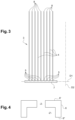
- FIG. 3 is a representation of a tuft of bristles.
- FIG. 4 is a view, in cross section through the wall, of a surface portion of the molded brush of FIG. 2 , a surface portion crossed by a hole formed after the spikes of the molded brush of FIG. 2 have been cut and the through and non-through holes have been made.
- FIG. 5 is a representation of the result of the phase of inserting a tuft of bristles into the hole represented in FIG. 4 .
- FIG. 6 is a perspective view of a two-part overmolding mold.
- FIG. 7 is a schematic representation of a flowchart of the steps of the method according to the invention.
- FIG. 8 is a perspective view of a connector according to a first variant, with a hexagonal-based gripping handle.
- FIG. 9 is a perspective view of a connector according to a second variant with a square-based gripping handle.
- FIG. 10 is a perspective view from another angle, of a support, provided with a connector according to the first variant.
- the invention concerns a method 100 for manufacturing the brushing part 1 ; a flowchart of the steps in the implementation of said method 100 is schematically represented in FIG. 7 .
- the method 100 comprises a first step 101 of providing a support 1 ′ for the brushing part 1 ;
- said support 1 ′ is made of a flexible plastic material, for example a thermoplastic elastomer or a silicone, preferably a Styrene-Ethylene-Butylene-Styrene.
- the support 1 ′ is drilled with through holes 2 , said holes passing through the mouth guard 6 formed by the support 1 ′, between an internal side 6 ′ and an external side 6 ′′ opposite to an internal side 6 ′ of the mouth guard 6 ;
- FIG. 1 represents a support 1 ′ such as provided during the first step 101 of the method 100 for manufacturing the brushing part 1 , according to one embodiment.
- FIG. 2 represents a support 1 ′, as provided during the first step 101 of the method 100 for manufacturing the brushing part 1 , according to another embodiment.
- the support 1 ′ is configured in a U-shape to be placed on the dentition of a jaw of a user. More precisely, the support 1 ′ has the shape of a mouth guard 6 , the mouth guard 6 being configured in a U-shape; the support 1 ′ is thus intended to receive all or part of this dentition.
- the support 1 ′ could also be called mouth guard 6 in the remainder of this description.
- the support 1 ′, or the mouth guard 6 includes a concave internal face 6 ′ and an external face 6 ′′.
- the brushing part 1 comprises one or more tufts 3 of bristles 4 , so the method 100 makes it possible to arrange and distribute over the internal face 6 ′ of the mouth guard 6 , the tufts 3 projecting inside this mouth guard 6 ; a tuft 3 of bristles 4 is schematically represented in FIG. 3 , and the formation of a tuft 3 is described in more detail below.
- the step of providing the support 1 ′ comprises a step of manufacturing 101 the support during which the support 1 ′ of the brushing part 1 is molded from a manufacturing mold, the mold itself being U-shaped like the support 1 ′.
- the manufacturing mold is in two parts, with one part configured to fill the internal space 6 ′ of the mouth guard 6 of the support 1 ′ molded with the mold.
- the mold can be designed to produce a support 1 ′ with a smooth internal face 6 ′, without holes or spikes, as illustrated in FIG. 1 a .
- the mold can also be designed to produce a support 1 ′ directly with holes passing through the wall of the mouth guard 6 , as will be described in more detail below.
- the mold can be designed to produce a support 1 ′ with spikes on the internal face 6 ′ of the mouth guard 6 , as illustrated in FIG. 2 ; for this, a mold in two parts 9 a , 9 b like the mold 9 of FIG. 6 can for example be used, with a part 9 a including holes 9 c ; thus, the support 1 ′ produced with the mold 9 includes, on the internal face 6 ′ of the mouth guard 6 , spikes, said spikes corresponding to said holes 9 c formed in the part 9 a of the mold 9 .
- the support 1 ′ provided during the manufacturing step 101 must include through holes 2 which pass through the mouth guard 6 formed by the support 1 ′, between the internal side 6 ′ and the external side 6 ′′ of the mouth guard 6 . If the support 1 ′, obtained in the manufacturing step 101 , includes spikes, the spikes are removed before proceeding to a step of drilling 102 through holes 2 , which follows the manufacture of the support 1 ′.
- FIGS. 1 b and 1 c show examples of support 1 ′ drilled with through holes 2 .
- the step of drilling 102 through holes 2 also comprises the drilling of another non-through hole 2 ′ corresponding to at least one through hole 2 , at least one through hole 2 being drilled according to a first diameter and about a first axis, and the other non-through hole 2 ′, being drilled according to a second diameter about the first axis, the second diameter being greater than the first diameter, the other non-through hole 2 ′ being emerging on the external side 6 ′′ of the mouth guard 6 .
- FIG. 1 c shows an example of a support 1 ′ drilled with holes, each hole comprising a through hole 2 and a corresponding non-through hole 2 ′.
- the diameter of a hole or any object here designates the line segment, and/or the length of the line segment of greatest length which connects two points of a circumference or of a perimeter of the hole or of the considered object.
- This definition is applied to all forms of circumference or perimeter of a hole or object; thus, said circumference or said perimeter can be circular, or elliptical, for example.
- the first diameter is determined based on the diameter of a cross section of the tufts 3 , so that the diameter of a through hole 2 is always less than the diameter of a cross section of the tuft 3 which is inserted inside said through hole.
- the first diameter is comprised between 0.2 mm and 2 mm.
- a forcefully inserting step 104 is made possible by the flexibility of the material constituting the support 1 ′, which can be sufficiently deformed to enlarge the hole and allow the insertion of the tuft into the hole, and which is sufficiently elastic to take up its shape after the insertion step 104 so as to generate a first level of mechanical retention of the tuft inserted in the through hole 2 .
- the second diameter, that of the non-through holes 2 ′, is greater than the largest dimension of the merged base 7 of the tufts 3 , which must be housed inside the non-through holes 2 ′, the definition of the merged base 7 of the tufts 3 being described below.
- the merged base 7 of the tufts 3 is housed in a non-through hole 2 ′ and bears on the bottom of said non-through hole 2 ′. According to these arrangements, an appropriate depth of the non-through hole determines an insertion depth of the tufts, and therefore a length of the free end.
- the drilling of a through hole 2 is simultaneous with the drilling of the other non-through hole 2 ′, corresponding to said through hole, for example by using a single drill with two different diameters, also called a counterbore drill.
- the step 101 of manufacturing the support 1 ′, by molding for example, and the step of drilling 102 through 2 and non-through 2 ′ holes are simultaneous;
- the simultaneity of the molding and the formation of said holes is obtained, for example, with the use of a mold provided with spikes projecting from the surface of said mold, each of said spikes having a shape corresponding to the hollow volume delimited, in the wall of the support 1 ′, by the edges of a through hole 2 and the edges of a corresponding non-through hole 2 ′.
- the next step of the method 100 according to the invention concerns the preparation of the tufts 3 .
- Each tuft 3 comprises a plurality of bristles 4 assembled by one end 5 so as to form a base of the tuft 3 , as illustrated in FIG. 3 ; the base of at least one tuft 3 , comprising the assembly formed by the juxtaposition of one of the ends 5 of the bristles assembled into a tuft 3 , is merged 7 , by heating for example, so as to form a merged zone 7 , said merged zone being integrally formed in the material of the bristles 4 .
- the material of the bristles can be nylon, or animal silk, or else polybutylene terephthalate (PBT) for example.
- the bristles 4 of a tuft 3 have a length preferably less than 10 mm.
- the bristles are preferably substantially straight filaments, preferably ultra-fine, that is to say the diameter of the filaments is comprised between 60 ⁇ m and 120 ⁇ m, preferably 80 ⁇ m. Thanks to these arrangements, the bristles have dimensions compatible with the internal dimensions of the brushing part and can be arranged inside the mouth guard 6 to effectively brush the dentition also placed inside the mouth guard 6 .
- each tuft 3 is longer in a direction of extension D2, than it is wide or thick, in a direction D1 transverse to the direction D2.
- the extension in the direction D1 of the base of a tuft 3 before the merging 103 of the ends 5 of the bristles 4 forming the base of the tuft is less than the extension in the direction D1 of the merged zone 7 .
- the fusion of the material of the bristles at the ends 5 causes expansion of the base of the tuft 3 , which thus assumes the shape of an inverted mushroom as illustrated in FIG. 3 .
- the free ends 8 of the bristles 4 of a tuft 3 can be rounded for efficient brushing without risk for the gum tissue.
- each tuft 3 is forcefully inserted into one of the through holes 2 formed in the wall of the support 1 ′, i.e. in the wall of the mouth guard 6 , during a forcefully insertion step 104 ; the forcefully insertion is carried out in such a way that finally the free ends 8 of the bristles 4 of each tuft 3 project on the internal face 6 ′ of the wall of the mouth guard 6 of the brushing part 1 , while the merged zone 7 of a tuft 3 is placed on the side of the external face 6 ′′ of this wall.
- the cross-section of the through hole 2 is always smaller than the cross-section of the tuft 3 which is inserted inside said through hole 2 , so that the tuft 3 is firmly held in and by the edges of the through hole 2 of the mouth guard 6 .
- the merged zone 7 of a tuft 3 is housed in the cavity formed by the non-through hole 2 ′ corresponding to the through hole 2 , on the side of the external face 6 ′′ of this wall, as represented in FIG. 5 .
- the material used to form the wall of the mouth guard 6 is, as indicated above, a flexible plastic material; according to one embodiment, this flexible plastic material allows the shape of the support 1 ′ to be adjusted by hot deformation 107 of the brushing part 1 , in order to best adapt it to the shape of the dentition of the user of the brushing part 1 .
- This step of hot deformation 107 is carried out after the step 104 of forcefully inserting the tufts 3 .
- a step of depositing 105 an adhesive at the level of the merged zone of the tuft 3 , after the step of forcefully inserting 104 the tufts 3 in the holes 2 , can be provided.
- the adhesion between the tuft 3 and the support 1 ′ can withstand a tensile force of at least 15 Newtons.
- the adhesive is an adhesive which polymerizes under the action of ultraviolet rays, in other words a UV adhesive.
- the step of depositing the adhesive comprises a polymerization step.
- a step 106 of filling the non-through holes 2 ′ can be provided.
- the filling 106 of the holes 2 ′ is made with a resin.
- the filling 106 of the holes 2 ′ is made by overmolding.
- the hot deformation step 107 is carried out after the step 104 of forcefully inserting the tufts 3 .
- the step of hot deforming 107 the brushing part can be carried out before the step of depositing 105 an adhesive, and of filling 106 the non-through holes 2 ′. According to these arrangements, the shape of the brushing part is better suited to the user dentition, and the adhesive and the filling material are preserved from the effects of the hot deformation step.
- the step of hot deforming 107 the brushing part can be carried out after the steps of depositing 105 an adhesive, and of filling 106 the non-through holes 2 ′.
- the step of hot deforming 107 the brushing part can be carried out before and after the steps of depositing 105 an adhesive, and of filling 106 the non-through holes 2 ′. According to these arrangements, the shape of the brushing part is even better adjusted to the user dentition.
- a plurality of tufts 3 are distributed over the internal faces of the wall of the mouth guard 6 ; as illustrated in FIGS. 1 to 3 , the direction of extension D2 of a tuft 3 has an inclination relative to the direction perpendicular to the face considered at the point where the tuft 3 projects on the face of the mouth guard 6 , which can vary between 0 degrees, for example for a tuft 3 planted at the bottom of the mouth guard 6 , and 45 degrees, for example, preferably directed towards the top of the mouth guard 6 , for a tuft 3 planted on the lateral parts of the internal side 6 ′ of the mouth guard 6 .
- the direction of extension D2 of a tuft 3 can form an angle of 90 degrees, for example with the direction of extension D2 of another tuft 3 . Thanks to these arrangements, the tufts of bristles are arranged to effectively brush the dentition positioned inside the mouth guard.
- the distribution of the projecting tufts of bristles on the internal face of the mouth guard 6 is adjusted so as to maximize the density of bristles locally and thus improve the efficiency of brushing.
- a staggered distribution of the holes on the overmolding mold can be selected.
- the brushing part 1 comprises a connector 14 , the connector 14 comprising a gripping handle 16 and at least one connection branch 15 fixed to one end of the gripping handle 16 ; an embodiment of a connector is illustrated in FIG. 8 and another embodiment is illustrated in FIG. 9 .
- Said at least one connection branch 15 has a shape conforming the U-shape of at least part of the external side 6 ′′ of the mouth guard 6 of the brushing part 1 , and the method 100 comprises the following additional steps:
- the fixing of the at least one connection branch 15 on the part of the external side 6 ′′ of the mouth guard 6 is carried out by overmolding.
- FIG. 10 illustrates an example of a support 1 ′ of a brushing part on which the connection branch 15 of a connector 16 has been attached, then fixed by overmolding.
- the invention concerns a brushing part 1 comprising a support 1 ′ configured in a U-shape to be placed on the dentition of a jaw of a user, the support forming a mouth guard 6 intended to receive on an internal side 6 ′ of all or part of this dentition, the support 1 ′ comprising at least one tuft 3 of brushing bristles 4 projecting on the internal side 6 ′ of the mouth guard 6 by a free end 8 of the bristles 4 of the at least one tuft 3 ,
- the merged zone 7 of at least one tuft 3 is inside another non-through hole 2 ′, formed in a wall of the mouth guard 6 , the other non-through hole 2 ′ being emerging on the external side 6 ′′ of the mouth guard 6 .
- the merged zone of the at least one tuft is adhered inside the non-through hole.
- the non-through hole is filled with a resin.
- the brushing part 1 comprises a connector 14 , the connector comprising a gripping handle 16 and at least one connection branch 15 fixed to one end of the gripping handle 16 , said at least one connection branch 15 having a shape which matches the U-shape of at least part of the external side 6 ′′ of the mouth guard 6 of the brushing part 1 , said at least one connecting branch 15 being attached on the part of the external side 6 ′′ of the mouth guard 6 .
- the connector is configured to transmit to the brushing part vibrations generated by a vibration generator on which is removably fixed another end of the gripping handle.
- At least one connection branch 15 has sufficient flexibility so as not to reduce the intrinsic flexibility of the mouth guard 6 , while transmitting the vibrations generated by the vibration generator.
- the other end of the gripping handle 16 configured to be fixed, in a removable manner, to the vibration generator, comprises a gripping wall, whose section is in the shape of a square or hexagon, said gripping wall being hollowed to allow the insertion of a fixing interface of the vibration generator.
- the hexagonal section of the gripping handle is configured with sides of unequal lengths, as illustrated in FIG. 10 , to act as a keying function at the interface between the gripping handle and the vibration generator.
Landscapes
- Health & Medical Sciences (AREA)
- Dentistry (AREA)
- General Health & Medical Sciences (AREA)
- Engineering & Computer Science (AREA)
- Life Sciences & Earth Sciences (AREA)
- Epidemiology (AREA)
- Animal Behavior & Ethology (AREA)
- Public Health (AREA)
- Veterinary Medicine (AREA)
- Manufacturing & Machinery (AREA)
- Chemical & Material Sciences (AREA)
- Materials Engineering (AREA)
- Mechanical Engineering (AREA)
- Brushes (AREA)
Abstract
Description
-
- forming the at least one tuft of bristles, by assembling a plurality of bristles by an end opposite the free end, so as to form a base of the at least one tuft, so that a diameter of one section of the at least one tuft, along a plane transverse to a direction of extension of the at least one tuft, that is to say greater than a diameter of the at least one through hole;
- merging the ends forming the base of the at least one tuft so as to form a merged zone in one part, so that an extension of the merged zone in a direction transverse to the direction of extension of the at least one tuft is greater than an extension of the base in the transverse direction before the merging step;
- forcefully inserting at least one tuft into at least one hole in the support mouth guard.
-
- a step of manufacturing the support;
- a step of drilling at least one hole passing through the mouth guard, between the internal side and an external side opposite to the internal side of the mouth guard, formed by the support;
- According to one embodiment, the step of manufacturing the support comprises a molding of the support from a molding mold.
-
- attaching the at least one connection branch to a part of the external side of the mouth guard;
- fixing the at least one connection branch on a part of the external side of the mouth guard.
-
- the at least one tuft of bristles, comprising a plurality of bristles assembled by one end, opposite the free end, so as to form a base of the at least one tuft;
- the base of the at least one tuft forming a merged zone in one part, an extension of the merged zone, in a direction transverse to a direction of extension of the at least one tuft, being greater than an extension from the base in the transverse direction before the formation of the merged zone;
- the at least one tuft of bristles passing through a hole passing through the mouth guard, between the internal side and an external side opposite to the internal side of the mouth guard formed by the support.
-
- attaching the at least one
connection branch 15 on a part of theexternal side 6″ of themouth guard 6; - fixing the at least one
connection branch 15 on a part of theexternal side 6″ of themouth guard 6.
- attaching the at least one
-
- the at least one
tuft 3 ofbristles 4, comprising a plurality of bristles (4) assembled by oneend 5, opposite to thefree end 8, so as to form a base of at least onetuft 3; - the base of at least one
tuft 3 forming amerged zone 7 in one part, an extension of themerged zone 7, in a direction D1 transverse to an extension direction D2 of at least onetuft 3, being greater than an extension of the base in the transverse direction D1 before the formation of themerged zone 7; - the at least one tuft of
bristles 3 passing through ahole 2 passing through themouth guard 6, between theinternal side 6′ and anexternal side 6″ opposite theinternal side 6′ of themouth guard 6, formed by thesupport 1′.
- the at least one
Claims (20)
Applications Claiming Priority (3)
| Application Number | Priority Date | Filing Date | Title |
|---|---|---|---|
| FR19/08872 | 2019-08-02 | ||
| FR1908872A FR3099350B1 (en) | 2019-08-02 | 2019-08-02 | Brushing part and method of manufacturing the brushing part. |
| PCT/FR2020/051188 WO2021023921A1 (en) | 2019-08-02 | 2020-07-06 | Brushing part and method for manufacturing the brushing part |
Publications (2)
| Publication Number | Publication Date |
|---|---|
| US20220279918A1 US20220279918A1 (en) | 2022-09-08 |
| US12150545B2 true US12150545B2 (en) | 2024-11-26 |
Family
ID=69190861
Family Applications (1)
| Application Number | Title | Priority Date | Filing Date |
|---|---|---|---|
| US17/632,206 Active 2041-02-04 US12150545B2 (en) | 2019-08-02 | 2020-07-06 | Brushing part and method for manufacturing the brushing part |
Country Status (6)
| Country | Link |
|---|---|
| US (1) | US12150545B2 (en) |
| EP (1) | EP4007509A1 (en) |
| KR (1) | KR20220088677A (en) |
| CN (1) | CN114513975B (en) |
| FR (1) | FR3099350B1 (en) |
| WO (1) | WO2021023921A1 (en) |
Families Citing this family (8)
| Publication number | Priority date | Publication date | Assignee | Title |
|---|---|---|---|---|
| USD951652S1 (en) | 2020-05-28 | 2022-05-17 | Lander Enterprises, Llc | Toothbrush head with double sided bristles |
| USD961075S1 (en) | 2020-10-30 | 2022-08-16 | Lander Enterprises, Llc | Automatic tongue scraper |
| USD958544S1 (en) | 2020-12-29 | 2022-07-26 | Lander Enterprises, Llc | Double-sided toothbrush head |
| USD959000S1 (en) | 2021-03-29 | 2022-07-26 | Lander Enterprises, Llc | Baby teether |
| USD983530S1 (en) | 2021-06-15 | 2023-04-18 | Lander Enterprises, Llc | Double-sided nylon toothbrush |
| USD1006450S1 (en) | 2021-11-30 | 2023-12-05 | Lander Enterprises, Llc | Toothbrush body |
| USD1023590S1 (en) | 2021-12-02 | 2024-04-23 | Lander Enterprises, Llc | Koala shaped automatic toothbrush |
| USD1023591S1 (en) | 2021-12-02 | 2024-04-23 | Lander Enterprises, Llc | Giraffe shaped automatic toothbrush |
Citations (4)
| Publication number | Priority date | Publication date | Assignee | Title |
|---|---|---|---|---|
| US4635313A (en) | 1983-11-16 | 1987-01-13 | North American Philips Corporation | Brush with self retaining bristles |
| US20140272761A1 (en) | 2007-07-05 | 2014-09-18 | Orthoaccel Technologies, Inc. | Massaging or brushing bite plates |
| US20160278511A1 (en) * | 2015-03-24 | 2016-09-29 | Jung Chan Ko | Mouthpiece type toothbrush and the operating method thereof |
| WO2019224450A1 (en) | 2018-05-22 | 2019-11-28 | Fasteesh | Method for manufacturing a dental brushing part, and dental brushing part |
Family Cites Families (3)
| Publication number | Priority date | Publication date | Assignee | Title |
|---|---|---|---|---|
| US4164940A (en) * | 1977-12-30 | 1979-08-21 | Quinby James D | Dental cleaning and massaging apparatus |
| CN2166673Y (en) * | 1993-07-22 | 1994-06-01 | 龙昌兄弟股份有限公司 | toothbrush |
| CN1294889A (en) * | 1999-11-09 | 2001-05-16 | 殷恒 | Toothbrush bristle capable of extending independently |
-
2019
- 2019-08-02 FR FR1908872A patent/FR3099350B1/en active Active
-
2020
- 2020-07-06 CN CN202080069704.8A patent/CN114513975B/en active Active
- 2020-07-06 US US17/632,206 patent/US12150545B2/en active Active
- 2020-07-06 EP EP20750310.3A patent/EP4007509A1/en active Pending
- 2020-07-06 KR KR1020227006850A patent/KR20220088677A/en active Pending
- 2020-07-06 WO PCT/FR2020/051188 patent/WO2021023921A1/en not_active Ceased
Patent Citations (5)
| Publication number | Priority date | Publication date | Assignee | Title |
|---|---|---|---|---|
| US4635313A (en) | 1983-11-16 | 1987-01-13 | North American Philips Corporation | Brush with self retaining bristles |
| US20140272761A1 (en) | 2007-07-05 | 2014-09-18 | Orthoaccel Technologies, Inc. | Massaging or brushing bite plates |
| US20160278511A1 (en) * | 2015-03-24 | 2016-09-29 | Jung Chan Ko | Mouthpiece type toothbrush and the operating method thereof |
| WO2019224450A1 (en) | 2018-05-22 | 2019-11-28 | Fasteesh | Method for manufacturing a dental brushing part, and dental brushing part |
| US20210161287A1 (en) | 2018-05-22 | 2021-06-03 | Fasteesh | Method for manufacturing a dental brushing part, and dental brushing part |
Non-Patent Citations (4)
| Title |
|---|
| English Translation of Written Opinion for International Application No. PCT/FR2020/051188; International Filing Date: Jul. 6, 2020; Date of Mailing: Sep. 11, 2020; 7 Pages. |
| International Search Report for International Application No. PCT/FR2020/051188; Date of Completion: Sep. 3, 2020; Date of Mailing: Sep. 11, 2020; 4 Pages. |
| Translation of International Search Report for International Application No. PCT/FR2020/051188; Date of Completion: Sep. 3, 2020; Date of Mailing: Sep. 11, 2020; 2 Pages. |
| Written Opinion for International Application No. PCT/FR2020/051188; International Filing Date: Jul. 6, 2020; Date of Mailing: Sep. 11, 2020; 6 Pages. |
Also Published As
| Publication number | Publication date |
|---|---|
| CN114513975A (en) | 2022-05-17 |
| FR3099350B1 (en) | 2024-07-12 |
| WO2021023921A1 (en) | 2021-02-11 |
| FR3099350A1 (en) | 2021-02-05 |
| EP4007509A1 (en) | 2022-06-08 |
| CN114513975B (en) | 2024-10-29 |
| US20220279918A1 (en) | 2022-09-08 |
| KR20220088677A (en) | 2022-06-28 |
Similar Documents
| Publication | Publication Date | Title |
|---|---|---|
| US12150545B2 (en) | Brushing part and method for manufacturing the brushing part | |
| US11925255B2 (en) | Method for manufacturing a dental brushing part, and dental brushing part | |
| US6311360B1 (en) | Brush and method of producing the same | |
| KR101022855B1 (en) | Toothbrush and method for production of such a toothbrush | |
| EP1827164B1 (en) | Toothbrush and method of making the same | |
| CN101883507B (en) | Oral care implement having one or more moving sections | |
| KR101203086B1 (en) | Toothbrush | |
| EP2000051B1 (en) | Toothbrush with enhanced cleaning effects | |
| CN102076244B (en) | Oral care implement having flexible supported cleaning elements extending in opposite directions | |
| KR20020059351A (en) | Brush, especially toothbrush | |
| AU6432600A (en) | Method and device for producing brushes and brushes produced using the same | |
| JP2018514253A (en) | Brush head assembly and manufacturing method | |
| JP2023511047A (en) | Method of manufacturing bristle pad and mouthpiece for brushing multiple tooth positions and mouthpiece and bristle pad | |
| JP2002010832A (en) | toothbrush | |
| US20240206622A1 (en) | Oral Care Implement | |
| US11172755B2 (en) | Oral care mouthpiece with brushing elements | |
| JP2003189940A (en) | toothbrush | |
| CN222738038U (en) | Electric toothbrush head and electric toothbrush | |
| JP2015091283A (en) | Toothbrush | |
| US20250057307A1 (en) | Oral care implement | |
| CN222752173U (en) | Electric toothbrush head and electric toothbrush | |
| KR20140017828A (en) | Toothbrush and its manufacturing method | |
| US20170156483A1 (en) | Toothbrush with Elastic Bristles | |
| TW202339646A (en) | Bristle tuft assembly and associated fabrication methods | |
| JP2002136340A (en) | toothbrush |
Legal Events
| Date | Code | Title | Description |
|---|---|---|---|
| FEPP | Fee payment procedure |
Free format text: ENTITY STATUS SET TO UNDISCOUNTED (ORIGINAL EVENT CODE: BIG.); ENTITY STATUS OF PATENT OWNER: SMALL ENTITY |
|
| AS | Assignment |
Owner name: FASTEESH, FRANCE Free format text: ASSIGNMENT OF ASSIGNORS INTEREST;ASSIGNORS:CADOT, CHRISTOPHE;COHEN, BENJAMIN;REEL/FRAME:058933/0650 Effective date: 20220202 |
|
| FEPP | Fee payment procedure |
Free format text: ENTITY STATUS SET TO SMALL (ORIGINAL EVENT CODE: SMAL); ENTITY STATUS OF PATENT OWNER: SMALL ENTITY |
|
| STPP | Information on status: patent application and granting procedure in general |
Free format text: DOCKETED NEW CASE - READY FOR EXAMINATION |
|
| STPP | Information on status: patent application and granting procedure in general |
Free format text: NON FINAL ACTION MAILED |
|
| STPP | Information on status: patent application and granting procedure in general |
Free format text: RESPONSE TO NON-FINAL OFFICE ACTION ENTERED AND FORWARDED TO EXAMINER |
|
| STPP | Information on status: patent application and granting procedure in general |
Free format text: NOTICE OF ALLOWANCE MAILED -- APPLICATION RECEIVED IN OFFICE OF PUBLICATIONS |
|
| ZAAB | Notice of allowance mailed |
Free format text: ORIGINAL CODE: MN/=. |
|
| STPP | Information on status: patent application and granting procedure in general |
Free format text: AWAITING TC RESP, ISSUE FEE PAYMENT VERIFIED |
|
| STCF | Information on status: patent grant |
Free format text: PATENTED CASE |