US12145401B2 - Bicycle wheel rim and process for manufacturing the same - Google Patents
Bicycle wheel rim and process for manufacturing the same Download PDFInfo
- Publication number
- US12145401B2 US12145401B2 US17/487,075 US202117487075A US12145401B2 US 12145401 B2 US12145401 B2 US 12145401B2 US 202117487075 A US202117487075 A US 202117487075A US 12145401 B2 US12145401 B2 US 12145401B2
- Authority
- US
- United States
- Prior art keywords
- structural fibers
- perforated
- cut
- fibers
- portions
- Prior art date
- Legal status (The legal status is an assumption and is not a legal conclusion. Google has not performed a legal analysis and makes no representation as to the accuracy of the status listed.)
- Active, expires
Links
Images


Classifications
-
- B—PERFORMING OPERATIONS; TRANSPORTING
- B60—VEHICLES IN GENERAL
- B60B—VEHICLE WHEELS; CASTORS; AXLES FOR WHEELS OR CASTORS; INCREASING WHEEL ADHESION
- B60B5/00—Wheels, spokes, disc bodies, rims, hubs, wholly or predominantly made of non-metallic material
- B60B5/02—Wheels, spokes, disc bodies, rims, hubs, wholly or predominantly made of non-metallic material made of synthetic material
-
- B—PERFORMING OPERATIONS; TRANSPORTING
- B29—WORKING OF PLASTICS; WORKING OF SUBSTANCES IN A PLASTIC STATE IN GENERAL
- B29C—SHAPING OR JOINING OF PLASTICS; SHAPING OF MATERIAL IN A PLASTIC STATE, NOT OTHERWISE PROVIDED FOR; AFTER-TREATMENT OF THE SHAPED PRODUCTS, e.g. REPAIRING
- B29C70/00—Shaping composites, i.e. plastics material comprising reinforcements, fillers or preformed parts, e.g. inserts
- B29C70/04—Shaping composites, i.e. plastics material comprising reinforcements, fillers or preformed parts, e.g. inserts comprising reinforcements only, e.g. self-reinforcing plastics
- B29C70/28—Shaping operations therefor
- B29C70/40—Shaping or impregnating by compression not applied
- B29C70/42—Shaping or impregnating by compression not applied for producing articles of definite length, i.e. discrete articles
- B29C70/46—Shaping or impregnating by compression not applied for producing articles of definite length, i.e. discrete articles using matched moulds, e.g. for deforming sheet moulding compounds [SMC] or prepregs
-
- B—PERFORMING OPERATIONS; TRANSPORTING
- B29—WORKING OF PLASTICS; WORKING OF SUBSTANCES IN A PLASTIC STATE IN GENERAL
- B29C—SHAPING OR JOINING OF PLASTICS; SHAPING OF MATERIAL IN A PLASTIC STATE, NOT OTHERWISE PROVIDED FOR; AFTER-TREATMENT OF THE SHAPED PRODUCTS, e.g. REPAIRING
- B29C70/00—Shaping composites, i.e. plastics material comprising reinforcements, fillers or preformed parts, e.g. inserts
- B29C70/04—Shaping composites, i.e. plastics material comprising reinforcements, fillers or preformed parts, e.g. inserts comprising reinforcements only, e.g. self-reinforcing plastics
- B29C70/28—Shaping operations therefor
- B29C70/54—Component parts, details or accessories; Auxiliary operations, e.g. feeding or storage of prepregs or SMC after impregnation or during ageing
- B29C70/545—Perforating, cutting or machining during or after moulding
-
- B—PERFORMING OPERATIONS; TRANSPORTING
- B60—VEHICLES IN GENERAL
- B60B—VEHICLE WHEELS; CASTORS; AXLES FOR WHEELS OR CASTORS; INCREASING WHEEL ADHESION
- B60B1/00—Spoked wheels; Spokes thereof
- B60B1/003—Spoked wheels; Spokes thereof specially adapted for bicycles
-
- B—PERFORMING OPERATIONS; TRANSPORTING
- B60—VEHICLES IN GENERAL
- B60B—VEHICLE WHEELS; CASTORS; AXLES FOR WHEELS OR CASTORS; INCREASING WHEEL ADHESION
- B60B21/00—Rims
- B60B21/06—Rims characterised by means for attaching spokes, i.e. spoke seats
- B60B21/062—Rims characterised by means for attaching spokes, i.e. spoke seats for bicycles
-
- B—PERFORMING OPERATIONS; TRANSPORTING
- B60—VEHICLES IN GENERAL
- B60B—VEHICLE WHEELS; CASTORS; AXLES FOR WHEELS OR CASTORS; INCREASING WHEEL ADHESION
- B60B21/00—Rims
- B60B21/06—Rims characterised by means for attaching spokes, i.e. spoke seats
- B60B21/064—Rims characterised by means for attaching spokes, i.e. spoke seats characterised by shape of spoke mounting holes, e.g. elliptical or triangular
-
- B—PERFORMING OPERATIONS; TRANSPORTING
- B29—WORKING OF PLASTICS; WORKING OF SUBSTANCES IN A PLASTIC STATE IN GENERAL
- B29L—INDEXING SCHEME ASSOCIATED WITH SUBCLASS B29C, RELATING TO PARTICULAR ARTICLES
- B29L2031/00—Other particular articles
- B29L2031/30—Vehicles, e.g. ships or aircraft, or body parts thereof
- B29L2031/3091—Bicycles
-
- B—PERFORMING OPERATIONS; TRANSPORTING
- B60—VEHICLES IN GENERAL
- B60B—VEHICLE WHEELS; CASTORS; AXLES FOR WHEELS OR CASTORS; INCREASING WHEEL ADHESION
- B60B2310/00—Manufacturing methods
- B60B2310/20—Shaping
- B60B2310/204—Shaping by moulding, e.g. injection moulding, i.e. casting of plastics material
-
- B—PERFORMING OPERATIONS; TRANSPORTING
- B60—VEHICLES IN GENERAL
- B60B—VEHICLE WHEELS; CASTORS; AXLES FOR WHEELS OR CASTORS; INCREASING WHEEL ADHESION
- B60B2310/00—Manufacturing methods
- B60B2310/20—Shaping
- B60B2310/226—Shaping by cutting
-
- B—PERFORMING OPERATIONS; TRANSPORTING
- B60—VEHICLES IN GENERAL
- B60B—VEHICLE WHEELS; CASTORS; AXLES FOR WHEELS OR CASTORS; INCREASING WHEEL ADHESION
- B60B2360/00—Materials; Physical forms thereof
- B60B2360/30—Synthetic materials
- B60B2360/34—Reinforced plastics
- B60B2360/341—Reinforced plastics with fibres
-
- B—PERFORMING OPERATIONS; TRANSPORTING
- B60—VEHICLES IN GENERAL
- B60B—VEHICLE WHEELS; CASTORS; AXLES FOR WHEELS OR CASTORS; INCREASING WHEEL ADHESION
- B60B2900/00—Purpose of invention
- B60B2900/10—Reduction of
- B60B2900/113—Production or maintenance time
-
- B—PERFORMING OPERATIONS; TRANSPORTING
- B60—VEHICLES IN GENERAL
- B60B—VEHICLE WHEELS; CASTORS; AXLES FOR WHEELS OR CASTORS; INCREASING WHEEL ADHESION
- B60B2900/00—Purpose of invention
- B60B2900/30—Increase in
- B60B2900/311—Rigidity or stiffness
-
- B—PERFORMING OPERATIONS; TRANSPORTING
- B60—VEHICLES IN GENERAL
- B60B—VEHICLE WHEELS; CASTORS; AXLES FOR WHEELS OR CASTORS; INCREASING WHEEL ADHESION
- B60B2900/00—Purpose of invention
- B60B2900/70—Adaptation for
- B60B2900/711—High loads, e.g. by reinforcements
Definitions
- the invention relates to a rim for a bicycle wheel and a process for manufacturing the aforementioned rim.
- Rims made of composite material are known. They are usually manufactured through molding of the composite material according to a variety of shapes in cross section.
- thermosetting polymeric material a compression molding is carried out
- thermoplastic polymeric material an injection molding or a thermoforming is carried out.
- a plurality of perforated spoke-attachment seats must be made in the rim before associating the rim with a hub to form a bicycle wheel.
- the aforementioned perforated seats must be made in the positions required by the spoke pattern of the particular wheel, depending on the number of spokes, their distribution along the circumference of the rim, their position in the cross section of the rim, and the direction taken up by each spoke, for example by virtue of the radial or tangential attachment of the spoke to the hub and/or of the camber angle.
- Patent application no. EP 2422959 to the Applicant and patent U.S. Ser. No. 10/315,461 disclose processes for manufacturing bicycle wheel rims made of composite material in which the plurality of perforated spoke-attachment seats is made before molding the composite material so that, after molding, bicycle wheel rims are obtained which are already provided with the aforementioned perforated seats.
- the perforated spoke-attachment seats are formed in the desired positions through a displacement of the structural fibers before molding the composite material.
- such a displacement is carried out by using a non-cutting pointed tool, like for example an awl.
- a non-cutting pointed tool like for example an awl.
- Such a tool once inserted in the composite material, causes a localized displacement of the structural fibers, without cutting or shearing or removing structural fibers (except possibly for a very limited number of structural fibers, in particular those structural fibers which are located right at the tip end of the tool).
- the displacement of the structural fibers results, in the case of unidirectional fibers, in the presence of two areas comprising an amassment of continuous (i.e. not cut) structural fibers arranged at diametrically opposite areas with respect to the perforated seat and along a substantially transversal direction with respect to the longitudinal direction of the structural fibers.
- the displacement of the weft structural fibers and warp structural fibers results in the presence of four areas comprising an amassment of continuous structural fibers at four areas spaced apart by about 90° around the perforated seat.
- the technical problem at the basis of the invention is to make a rim made of composite material that can better and more quickly withstand the aforementioned mechanical stresses.
- the present invention relates to a bicycle wheel rim comprising a wall made of composite material having a plurality of perforated spoke-attachment seats, wherein at least one of said perforated seats is at least in part delimited by:
- FIG. 1 is a bicycle wheel with a rim according to the present invention
- FIG. 2 is a plan view of a portion of the composite material provided in a prior art rim
- FIG. 3 is a plan view of a portion of the composite material provided in a first preferred embodiment of the rim according to the present invention
- FIG. 4 is a plan view of a portion of the composite material provided in a second preferred embodiment of the rim according to the present invention.
- FIG. 5 illustrates a first manufacturing step for a bicycle rim according to the process of the present invention
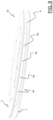
- FIG. 6 is a partially section of the manufacturing step looking in the direction of 6 - 6 in FIG. 5 ;
- FIG. 7 is a perspective view of a cutting tool used in the manufacturing step of FIG. 5 ;
- FIG. 8 schematically illustrates a second manufacturing step according to the process of the present invention, such a second step being subsequent to the one of FIG. 5 ;
- FIG. 9 illustrates a third manufacturing step according to the process of the present invention, which is subsequent to the one of FIG. 8 ;
- FIG. 10 illustrates a fourth manufacturing step according to the process of the present invention, which is subsequent to the one of FIG. 9 .
- the rim of the invention comprises a composite material, at least in a wall thereof in which the perforated spoke-attachment seats are made.
- a rim will also be identified with the expression “rim made of composite material”.
- the term “perforated spoke-attachment seat” is used in a broad sense, to include both a seat in which a spoke is directly inserted, the spoke being for example provided with an enlarged head and/or with a threading, and a seat in which it is inserted a nipple or other element with which the spoke is associated.
- composite material is used to indicate a material comprising a plurality of structural fibers incorporated in a polymeric material.
- the aforementioned structural fibers are unidirectional or bi-directional fibers.
- a single layer of unidirectional fibers or at least two juxtaposed layers of unidirectional fibers inclined with respect to one another can be provided, with the structural fibers of each layer arranged so that, in areas of the rim far from the perforated spoke-attachment seats, they extend substantially parallel to one another along a respective longitudinal direction.
- the composite material defines a fabric comprising a first plurality of substantially parallel structural fibers extending along the aforementioned first longitudinal direction (weft fibers) and a second plurality of substantially parallel structural fibers extending along a second direction substantially perpendicular to the aforementioned first direction (warp fibers).
- unidirectional fibers the structural fibers of a layer of unidirectional fibers will be referred to.
- condition of mutual juxtaposition is used to indicate both a relative position of the first portions of continuous structural fibers and of the end portions of the structural fibers of the second plurality of cut structural fibers such that the end portions of the structural fibers of the second plurality of cut structural fibers are radially juxtaposed over the first portions of continuous structural fibers, and a relative position of the first portions of continuous structural fibers and of the end portions of the structural fibers of the second plurality of cut structural fibers such that the first portions of continuous structural fibers are radially juxtaposed over the end portions of the structural fibers of the second plurality of cut structural fibers.
- condition of mutual interposition is used to indicate a relative position of the first portions of continuous structural fibers and of the end portions of the structural fibers of the second plurality of cut structural fibers such that the end portions of the structural fibers of the second plurality of cut structural fibers are radially interposed between the first portions of continuous structural fibers and/or vice-versa.
- radially when used with reference to the structural fibers, indicates a direction taken along any radius of a circumference that delimits the perforated spoke-attachment seat. Such a direction is also indicated as “radial direction”.
- radially outer when used with reference to the structural fibers, indicates a radial direction oriented from the center of the aforementioned circumference towards the outside of such a circumference.
- radially inner when used with reference to the structural fibers, indicates a radial direction oriented from the outside of the aforementioned circumference towards the center of such a circumference.
- circumferentially when used with reference to the structural fibers, indicates a direction taken along a circumference that delimits the perforated spoke-attachment seat.
- the rim of the invention is capable of responding to the mechanical stresses which it is subjected to during use more quickly and efficiently than the rims described in EP 2422959 and U.S. Ser. No. 10/315,461.
- This is due to the provision of portions of structural fibers in all of the areas around each perforated seat, and thus also in those areas in which, in the rims described in EP 2422959 and U.S. Ser. No. 10/315,461, the fibers have been displaced leaving only polymeric material there.
- the rim of the invention has, around the perforated spoke-attachment seats, areas of amassment of end portions of cut structural fibers and of portions of continuous structural fibers.
- areas of amassment of fibers allow the rim to effectively withstand and transfer the stresses which it is subjected to at the perforated spoke-attachment seats.
- a gradual and continuous transfer of the mechanical stresses from the end portions of the cut structural fibers to the continuous structural fibers occurs, to the benefit of the structural strength of the rim.
- the term “area of amassment of structural fibers” is used to indicate an area in which the local density of the structural fibers is greater than an average nominal density of the structural fibers in the composite material. Therefore, if the composite material has a certain average nominal density of structural fibers, it will have, in every area of the wall of the rim far from the perforated spoke-attachment seats, a density of structural fibers in a tolerance range around the average nominal density and, in the area of amassment of structural fibers, a density of structural fibers greater than the upper limit of such a tolerance range.
- the area of amassment of structural fibers is obtained while the spoke-attachment seats are being made before molding the composite material, i.e. before the latter is cross-linked. In such circumstances, indeed, the structural fibers are capable of displacing with respect to the polymeric material because of the thrusting action exerted on them by the tool used to make the perforated spoke-attachment seats.
- the structural fibers provided in said at least one first area are only those of said first plurality of cut structural fibers.
- Such structural fibers occupy those areas in which in the rims described in EP 2422959 and U.S. Ser. No. 10/315,461 the structural fibers have been displaced leaving only polymeric material there, to the benefit of the structural strength of the rim at such areas.
- said at least one second area comprises at least one first zone in which both said end portions of said second plurality of cut structural fibers and said first portions of continuous structural fibers are provided and at least one second zone in which only second portions of said continuous structural fibers are provided.
- said at least one first zone is circumferentially interposed between said at least one first area and said at least one second zone.
- At least some of said end portions of said second plurality of cut structural fibers are at least partially arranged in a radially outer position with respect to said first portions of continuous structural fibers.
- At least some of said end portions of said second plurality of cut structural fibers are at least partially arranged in a radially inner position with respect to said first portions of continuous structural fibers.
- At least some of said end portions of said second plurality of cut structural fibers are in part arranged in a radially inner position with respect to said first portions of continuous structural fibers and in part arranged in a radially outer position with respect to said first portions of continuous structural fibers.
- the portions of cut structural fibers arranged in a radially inner position are adjacent to a first area and the portions of cut structural fibers arranged in a radially outer position are arranged on the opposite side to said first area with respect to the aforementioned portions of cut structural fibers arranged in a radially inner position.
- At least some of said end portions of said second plurality of cut structural fibers are grouped together to form respective strands of cut structural fibers.
- at such strands there is an amassment of cut structural fibers that produces an increase of the contribution provided by the end portions of cut structural fibers to the structural strength of the rim.
- said at least one perforated seat is at least in part delimited by two of said first areas and by two of said second areas.
- said two second areas are arranged at first angular sectors that are opposite with respect to said at least one perforated seat.
- angular sector is used to indicate an angular portion of the circumference that delimits the perforated spoke-attachment seat, such an angular portion having an angle to the center lower than 180°, preferably lower than or equal to 90°.
- the first angular sectors can be opposite with respect to a diametral plane of the perforated seat, but not aligned along a specific direction.
- the first angular sectors are diametrically opposite, i.e. opposite with respect to a diametral plane of the perforated seat and aligned along a radial direction.
- said two first areas are arranged at second angular sectors that are opposite with respect to said at least one perforated seat.
- the second angular sectors can be opposite with respect to a diametral plane of the perforated seat, but not aligned along a specific direction.
- the second angular sectors are diametrically opposite, i.e. opposite with respect to a diametral plane of the perforated seat and aligned along a radial direction.
- said two first areas are arranged along a first direction.
- the first direction is substantially parallel to a longitudinal direction of the continuous and cut structural fibers in areas far from the perforated seats.
- said two second areas are arranged along a second direction inclined with respect to the first direction by a first angle.
- the second direction is substantially perpendicular to the first direction.
- two of said first zones are arranged on opposite sides with respect to a diametral plane of the perforated seat.
- the aforementioned two first zones are arranged on diametrically opposite sides with respect to a diametral plane of the perforated seat, i.e. they are arranged along a single radial direction.
- said two first zones are aligned along a third direction that, preferably, is inclined with respect to the first direction by a second angle lower than said first angle.
- two of said second zones are arranged on opposite sides with respect to the perforated seat along said second direction.
- the structural fibers of said first plurality of cut structural fibers and second plurality of cut structural fibers occupy a space having, along a direction perpendicular to said longitudinal direction, a size greater than 10% of the diameter of the perforated seats. More preferably, said size is comprised between 20% and 70% of the diameter of the perforated seats, the extreme values being included. In particular, the aforementioned size is preferably comprised between 20% and 50% of the aforementioned diameter, the extreme values being included.
- the present invention relates to a process for manufacturing a bicycle wheel rim, comprising:
- compacting the composite material at each of said second through holes makes it possible to obtain the desired condition of mutual juxtaposition or of mutual interposition of the end portions of cut structural fibers and of the first portions of continuous structural fibers, to the benefit of the structural strength of the rim.
- said tip is heated.
- Such a provision makes it possible to increase the capability and speed of displacement of the structural fibers encountered by the non-cutting pointed tool during the movement thereof in the second through hole.
- compacting the composite material comprises:
- the aforementioned tip thus acts as a reference and a guide for the application and correct positioning of the respective insert on the rim being made.
- the insert is co-molded together with the composite material, so as to achieve an increase in the structural strength of the rim at the perforated spoke-attachment seats, as well as a more homogeneous distribution of the stresses which the rim is subjected to at such perforated seats. Moreover, the co-molding of the inserts prevents a friction wear due to the sliding of the insert on the composite material.
- said pressing tool comprises a first end portion having a top surface configured to be hit with a hammer.
- the pressing tool comprises a second end portion having a hollow cylindrical shape.
- pressing the composite material against said radially outer wall comprises fitting said second end portion onto the tip of each non cutting pointed tool until said second end portion abuts against the respective insert.
- the aforementioned tip thus acts as a reference and a guide for the pressing tool, thereby facilitating the correct positioning of the second end portion of the pressing tool on the respective insert and, consequently, the application of the insert on the rim being made.
- perforating the composite material comprises, at each of said first through holes, inserting the cutting tool in the first through hole along said insertion direction from a radially inner side of the mold.
- perforating the composite material comprises, after the aforementioned insertion, pushing the cutting tool along said insertion direction until the respective second through hole is made in the composite material.
- the second through holes are made at the first through holes of the mold.
- the movement of the cutting tool is thus guided by the aforementioned first through holes.
- the first through holes of the mold unequivocally define the position and the direction of the perforated seat, making the perforating operation extremely quick and precise.
- said mold has a substantially annular shape and comprises, on a radially inner surface thereof, a circumferential groove connected to said first through holes.
- the process according to the invention comprises, after having arranged the composite material in the mold and before perforating the composite material to make each second through hole, inserting the cutting tool in the circumferential groove and moving the cutting tool along the circumferential groove until the respective first through hole is reached.
- the cutting tool is therefore easily guided between the first through holes through the circumferential groove. Such a provision contributes to make the perforating operation quick and precise.
- perforating the composite material comprises, after having pushed the cutting tool along said first direction, removing the cutting tool from said second through hole by moving it along a second direction opposite to said first direction.
- the cutting tool comprises a cylindrical cutting portion and a conical cutting tip.
- the conical sharp tip makes it possible to precisely start the perforation, whereas the cylindrical cutting portion defines the diameter of the second hole, calibrating it to the desired size.
- said cylindrical cutting portion has a diameter comprised between 20% and 100% of the diameter of the second through holes, more preferably between 20% and 70% of the diameter of the second through holes.
- said conical cutting tip is diamond-tipped.
- the diamond-tipped tip has significant properties as to the cutting reliability and durability.
- each of said non cutting pointed tools comprises a cylindrical portion and a conical non cutting tip.
- said cylindrical portion has a diameter comprised between 90% and 100% of the diameter of the second through holes, preferably between 95% and 100% of the diameter of the second through holes, even more preferably between 97% and 100% of the diameter of the second through holes, for example equal to 98% of the diameter of the second through holes.
- a bicycle wheel rim according to the present invention is indicated as a whole with 50 .
- the bicycle wheel is indicated with 55 .
- the rim 50 is made, at least partially, of composite material 6 .
- the structural fibers of the composite material 6 are preferably selected from the group consisting of carbon fibers, glass fibers, boron fibers, aramid fibers, ceramic fibers and combinations thereof, wherein carbon fiber is preferred.
- the polymeric material of the composite material 6 can be thermoplastic or thermosetting.
- a polymeric material is a thermosetting resin.
- the mechanical characteristics of the composite material 6 can vary as a function of the type of structural fiber, of the type of weaving/arrangement thereof, of the type of polymeric material and of the percentage ratio between structural fiber and polymeric material.
- the structural fibers of the composite material 6 are unidirectional fibers.
- FIGS. 3 and 4 each illustrate a portion of a layer of unidirectional structural fibers 60 .
- the structural fibers of the composite material 6 can also be arranged in many juxtaposed layers.
- the unidirectional structural fibers 60 extend substantially parallel to one another along a longitudinal direction L, which can be parallel or inclined with respect to the circumferential direction of the rim 50 .
- many juxtaposed layers of unidirectional fibers are provided, said layers being arranged so that the directions of the unidirectional fibers of two adjacent layers form angles of opposite sign, and preferably of +45° and ⁇ 45°, with the circumferential direction of the rim 50 .
- the rim 50 has a predetermined rotation axis X and is mounted on a hub 54 of the bicycle wheel 55 through a plurality of spokes 52 .
- the rim 50 has a radially inner annular wall 56 made of composite material.
- a plurality of perforated spoke-attachment seats 58 preferably having a substantially circular shape and where the spokes 52 are mounted, is made on such an annular wall 56 .
- the rim 50 has a radially outer annular wall 57 having a plurality of through holes 57 a , each at a respective perforated seat 58 .
- the annular wall 56 has a symmetrical shape with respect to the rotation axis X and to a diametral middle plane perpendicular to the rotation axis X, and the spokes 52 extend along substantially radial directions.
- the annular wall 56 has a non-symmetrical shape and/or where the spokes 52 extend along directions inclined with respect to the radial direction.
- the terms “inner” and “outer” refer to the radial direction of the rim 50 or, in some contexts, they can refer to the direction taken up by a spoke 52 . In any case the aforementioned terms are used to indicate positions which are proximal and distal, respectively, with respect to the rotation axis X of the rim 50 .
- FIG. 2 shows, schematically and as an example, the progression of the unidirectional fibers close to a perforated spoke-attachment seat 58 a of a bicycle wheel rim according to a prior art analogous to that of the aforementioned documents EP 2422959 and U.S. Ser. No. 10/315,461.
- the perforated seat 58 a is formed, before the molding of the composite material, through displacement of unidirectional structural fibers 40 .
- the two areas 42 are arranged at diametrically opposite parts with respect to the perforated seat 58 a and along a transversal direction T that is substantially perpendicular to the longitudinal direction L of the unidirectional structural fibers 40 in areas far from the perforated seats 58 a.
- FIGS. 3 and 4 illustrate, schematically and as an example, the progression of the structural fibers close to a perforated seat 58 of the annular wall 56 of two preferred embodiments of the rim 50 .
- the composite material comprises unidirectional structural fibers 60 that, in areas far from the perforated seats 58 , extend along a longitudinal direction L.
- the longitudinal direction L can be parallel to the circumferential direction of the rim 50 or inclined with respect to the circumferential direction of the rim 50 , for example by about 45° or by about 60°.
- Each perforated seat 58 has a substantially circumferential shape and is delimited, along the entire perimeter circumference 59 thereof, by continuous unidirectional structural fibers 60 and by cut unidirectional structural fibers 60 .
- one or some or each of such perforated seats 58 are delimited by two first areas 62 comprising end portions of cut structural fibers 60 a and by two second areas 63 comprising both end portions of cut structural fibers 60 b and portions of continuous structural fibers 60 c.
- the cut structural fibers 60 b have a longitudinal dimension greater than that of the cut structural fibers 60 a and can be either in a condition of mutual juxtaposition with respect to the portions of continuous structural fibers 60 c or in a condition of mutual interposition with respect to the portions of continuous structural fibers 60 c.
- At least some of the end portions of cut structural fibers 60 b can be arranged in a radially outer position with respect to the portions of continuous structural fibers 60 c , or in a radially inner position with respect to the portions of continuous structural fibers 60 c , or in part in a radially outer position with respect to the portions of continuous structural fibers 60 c and in part in a radially inner position with respect to the portions of continuous structural fibers 60 c , or they can be interposed between the portions of continuous structural fibers 60 c.
- At least some of the end portions of cut structural fibers 60 b can have parts arranged in a radially inner position and/or in a radially outer position and/or in interposed with respect to the portions of continuous structural fibers 60 c.
- cut structural fibers 60 b can be grouped together to form respective strands of cut structural fibers.
- the structural fibers provided in the first areas 62 are only those of the first plurality of cut structural fibers 60 a , whereas in the second areas 63 only the end portions of cut structural fibers 60 b and the portions of continuous structural fibers 60 c are provided. Therefore, there are no parts of the perimeter circumference 59 of the perforated seat 58 at which only portions of continuous structural fibers 60 c are provided.
- the second areas 63 are circumferentially spaced apart from the first areas 62 .
- the two first areas 62 are arranged on diametrically opposite sides with respect to the perforated seat 58 along the longitudinal direction L and the two second areas 63 are arranged on diametrically opposite sides with respect to the perforated seat 58 along the transversal direction T. Therefore, the two first areas 62 are diametrically opposite and spaced apart by about 90° with respect to the two second areas 63 .
- the longitudinal direction L is substantially parallel to a longitudinal direction of the continuous structural fibers 60 c and of cut structural fibers 60 a , 60 b in areas far from the perforated seat 58 .
- the cut structural fibers 60 a of the first areas 62 have, close to the perforated seat 58 , a curvilinear shape, whereas in areas far from the perforated seat 58 they have a substantially rectilinear shape and are parallel to the longitudinal direction L. Close to the perimeter circumference 59 of the perforated seat 58 , the cut structural fibers 60 a tend to open with respect to a diametral plane A of the perforated seat 58 parallel to the longitudinal direction L, i.e. to take up inclinations with respect to the longitudinal direction L that are progressively greater as the second areas 63 and, therefore, the perforated seat 58 , are approached. Similarly, some of the cut structural fibers 60 b of the second areas 63 also open with respect to the diametral plane A of the perforated seat 58 .
- the cut structural fibers 60 a and 60 b occupy a space having, along the transversal direction T, a size greater than 10% of the diameter D of the perforated seats 58 .
- a size is comprised between 20% and 70% of the diameter D of the perforated seats 58 , the extreme values being included, more preferably between 20% and 50% of the diameter D.
- FIG. 4 shows a second embodiment of the rim 50 according to the invention, which differs from the embodiment of FIG. 3 only for the type of structural fibers provided in the second areas 63 .
- each of the two areas 63 comprises a first zone 63 ′ in which both end portions of cut structural fibers 60 b and first portions of the continuous structural fibers 60 c are provided and a second zone 63 ′′ in which only second portions of the continuous structural fibers 60 c are provided.
- the first zone 63 ′ is circumferentially interposed between a first area 62 and the second zone 63 ′′.
- the two first zones 63 ′ of the two second areas 63 are arranged on diametrically opposite sides with respect to the perforated seat 58 along a direction inclined with respect to the longitudinal direction L by an angle smaller than 90°, preferably comprised between 15° and 45°.
- the two second zones 63 ′′ of the two second areas 63 are arranged on diametrically opposite sides with respect to the perforated seat 58 along the transversal direction T.
- a first zone 63 ′ is provided in the quadrant Q 1 (and/or in the quadrant Q 3 ) and a second zone 63 ′′ is provided in the quadrant Q 2 (and/or in the quadrant Q 4 ).
- FIGS. 5 - 10 a preferred embodiment of the process for manufacturing a bicycle wheel rim according to the invention, like for example the rim 50 described above, is described.
- the process comprises molding the composite material in a mold 70 .
- the mold 70 has a substantially annular shape and comprises two annular elements 1 , 2 coupled together to define a mold cavity 3 .
- the mold cavity 3 is shaped to make a symmetrical rim 50 , in particular for tubeless tyres.
- the annular elements 1 , 2 when coupled, define a plurality of through holes 5 at which the perforated seats 58 will be made.
- FIG. 6 shows a right half-section of the mold 70 taken at a through hole 5 .
- the through hole 5 is made in part in the annular element 1 and in part in the annular element 2 and comprises a substantially cylindrical radially outer portion 5 a and a radially inner portion 5 b having a substantially frusto-conical shape flared inwardly, or a cylindrical shape.
- the radially outer portion 5 a has a diameter substantially equal to the nominal diameter D of the perforated spoke-attachment seats 58 , or slightly greater than the nominal diameter D.
- the radially outer portion 5 a extends along a direction that corresponds to the direction along which the spoke 52 housed in the perforated seat 58 of the rim 50 will extend.
- such a direction extends in the plane of FIG. 5 , that is in a transversal plane of the rim 50 , along a direction inclined with respect to the diametral middle plane Y of the mold 70 .
- the corresponding spoke 52 is therefore of the type configured for a radial attachment to the hub 54 with a certain camber.
- other through holes 5 are provided in suitable positions along the circumferential direction of the annular elements 1 , 2 , with suitable inclination of the relative radially outer portions 5 a depending on the desired camber.
- the through holes 5 in the annular elements 1 , 2 will have suitable directions and positions and some through holes 5 could also extend in only one of the annular elements 1 , 2 .
- the annular elements 1 , 2 preferably have abutment members (not shown) like for example pins and centering holes, reference marks and similar, to ensure that when they are coupled together, the two parts of each through hole 5 in the two annular elements 1 , 2 are correctly aligned to wholly define the through hole 5 itself.
- the mold 70 comprises, on a radially inner surface 71 thereof, a circumferential groove 72 connected to the through holes 5 .
- the process according to the invention initially comprises arranging the composite material 6 in the mold 70 , in particular on a radially outer wall 3 a of the mold cavity 3 .
- the mold cavity 3 is coated with one or more layers of sheeted composite material 6 , preferably preimpregnated.
- sheeted composite material 6 preferably preimpregnated.
- Such materials are in general known in the field as Sheet Moulding Compounds (SMC) or “prepreg”, and comprise substantially structural fibers preimpregnated with polymeric material.
- the arrangement of the composite material 6 in the mold cavity 3 can take place by hand or be automated.
- the composite material 6 is perforated at the through holes 5 through a cutting tool 80 , shown in FIG. 7 .
- the cutting tool 80 is a rotating tool, mounted on an angular screwdriver 90 (illustrated in FIGS. 5 and 6 ), or on a drill.
- the angular screwdriver 90 has the advantage of being able to be maneuvered easily in narrow spaces, like those inside the mold 70 .
- the cutting tool 80 comprises a cylindrical shank 81 having, at a free end thereof, a cylindrical cutting portion 84 and a conical cutting tip 86 . Both the cylindrical cutting portion 84 and the conical cutting tip 86 have at least one cutting edge 82 .
- there is more than one cutting edge 82 (for example four) and they extend seamlessly on the cylindrical cutting portion 84 and on the conical cutting tip 86 .
- the conical cutting tip 86 is diamond-tipped.
- the perforation of the composite material 6 through the cutting tool 80 produces in the composite material 6 a through hole 6 a at each through hole 5 of the mold 70 .
- the diameter of the cylindrical cutting portion 84 of the cutting tool 80 is selected as a function of the diameter of the through hole 6 a to be made, of the desired ratio between cut and continuous (uncut) structural fibers to be obtained at the through hole 6 a , as well as from industrial evaluations (needs to not break the cutting tool 80 and processing times).
- the cylindrical cutting portion 84 has a diameter comprised between 20% and 100% of the diameter of the through holes 6 a , more preferably between 20% and 70% of the diameter of the second through holes 6 a .
- a part of structural fibers can displace, as it is not yet blocked by the cross-linked polymeric material.
- a cutting tool 80 in order to make a through hole 6 a of diameter equal to 5 mm, it is possible to use a cutting tool 80 with a cylindrical cutting portion 84 having a diameter equal to 3.5 mm.
- the cutting tool 80 is used at room temperature, i.e. before being used it is not heated, so as to avoid portions of sheared structural fiber remaining stuck onto the surface thereof, which would worsen the quality and the dimensional precision of the through holes 6 a.
- the perforation of the composite material 6 to make the through holes 6 a initially comprises inserting the conical cutting tip 86 in the circumferential groove 72 and subsequently moving the cutting tool 80 along the circumferential groove 72 until each through hole 5 is reached.
- the cutting tool 80 is inserted into it along a first direction F, starting from the radially inner portion 5 b thereof.
- the substantially frusto-conical (or cylindrical) shape of the radially inner portion 5 b makes easier and guides the insertion of the cutting tool 80 .
- the cutting tool 80 reaches the substantially cylindrical radially outer portion 5 a of the through hole 5 and is pushed until the composite material 6 is reached and perforated, thus making the through hole 6 a in the composite material 6 .
- the cutting tool 80 is set in rotation in the clockwise direction.
- the cutting tool 80 is then removed from the through hole 5 , moving it along a direction B opposite to the insertion direction F.
- the conical tip 86 of the cutting tool 80 is thus moved at the circumferential groove 72 and run across it until the next through hole 5 is reached, where it carries out the perforation of the composite material 6 in the same way as described above.
- the cutting tool 80 is removed from the through hole 6 a , the latter is fine-finished to size through a non cutting pointed tool 8 , such as a pin, as illustrated in FIG. 9 .
- the term “finish to size” is used to indicate a mechanical operation that causes the displacement of cut structural fibers 60 a , 60 b and of continuous structural fibers 60 c until a desired size of the through hole 6 a in the composite material 6 is reached.
- Such a through hole 6 a defines, after the composite material 6 is molded, a nominal design size of the perforated spoke-attachment seat 58 .
- the polymeric material 6 is also displaced by the non cutting pointed tool 8 .
- a plurality of non cutting pointed tools 8 are preferably provided so as to be able to operate in series on a plurality of perforated seats 58 .
- Each non cutting pointed tool 8 comprises a cylindrical portion 8 a and a conical (or frusto-conical) non cutting tip 8 b.
- the diameter of the cylindrical portion 8 a corresponds substantially to the nominal diameter D of the perforated spoke-attachment seats 58 to be formed in the rim 50 , or it is slightly greater than such a nominal diameter D.
- the diameter of the cylindrical portion 8 a is substantially equal to or slightly smaller than the diameter of the radially outer portion 5 a of the through hole 5 .
- the diameter of the cylindrical portion 8 a is comprised between 90% and 100% of the diameter of the through holes 6 a , preferably between 95% and 100% of the diameter of the through holes 6 a , even more preferably between 97% and 100% of the diameter of the through holes 6 a , for example equal to 98% of the diameter of the through holes 6 a.
- the non cutting pointed tool 8 is inserted in the through hole 6 a along the first direction F from the through hole 5 , thus from the radially inner side of the mold 70 ( FIGS. 9 and 10 ). Such insertion is made easier by the substantially frusto-conical and flared inwardly shape of the radially inner portion 5 b of the through hole 5 .
- the non cutting pointed tool 8 then reaches the radially outer portion 5 a of the through hole 5 and is pushed until the non cutting pointed tool 8 reaches and passes the through hole 6 a , thereby fine-finishing it to size.
- the insertion of the non cutting pointed tool 8 thus proceeds until the conical non cutting tip 8 b and a part of the cylindrical portion 8 a project in a radially outer direction with respect to the composite material 6 .
- the non cutting pointed tool 8 can comprise an abutment shoulder 8 c configured to abut on the radially inner surface 71 of the mold 70 at the through hole 5 , so as to easily define the correct insertion depth of the non cutting pointed tool 8 in the mold 70 .
- Such an abutment shoulder 8 c is defined at an end of a grip portion 8 d of the non cutting pointed tool 8 , which is in a radially inner position with respect to the cylindrical portion 8 a thereof.
- the insertion of the non cutting pointed tool 8 in the through hole 6 a of the composite material 6 causes a displacement of the continuous structural fibers 60 c and of the cut structural fibers 60 a , 60 b , until a desired size of the through hole 6 a is reached.
- a desired size defines, after the subsequent molding of the composite material 6 , a nominal design size D of the perforated seat 58 .
- the diameter of the through hole 6 a after the fine-finishing to size made by the non cutting pointed tool 8 is greater than or equal to the diameter of the through hole 6 a after the perforation made by the cutting tool 80 , the latter depending on the diameter of the cylindrical cutting portion 84 of the cutting tool 80 .
- the latter follows the inclination of the radially outer portion 5 a of the through hole 5 in the inner elements 1 , 2 of mold 70 .
- the through hole 5 thus acts as a guide for the non cutting pointed tool 8 .
- the non cutting pointed tool 8 is used after at least the conical non cutting tip 8 b has been heated.
- the viscosity of the polymeric material decreases, promoting the displacement of the continuous structural fibers 60 a and of the cut structural fibers 60 b , 60 c.
- the temperature of the pointed tool 8 is lower than the cross-linking temperature thereof.
- the temperature of the pointed tool 8 can however also be greater than the cross-linking temperature.
- the pointed tool 8 is maintained in the through hole 6 a of the composite material 6 for a reduced time, so as not to cause an increase in the temperature of the composite material 6 such as to reach the cross-linking temperature.
- the heating must also take place at a temperature such as to avoid the polymeric material dripping in the through hole 5 .
- the heating temperature can be 80°-100°.
- the insertion of the non cutting pointed tool 8 in the composite material 6 ensures that some end portions of cut structural fibers 60 b project from the through hole 6 a towards the cavity 3 of the mold 70 .
- a subsequent compacting of the composite material 6 at each of the through holes 6 a is thus carried out.
- Such compacting ensures that the aforementioned end portions of cut structural fibers 60 b projecting with respect to the through hole 6 a are folded towards the portions of continuous structural fibers 60 c arranged around the perimeter circumference 59 of the perforated seat 58 , preferably creating the aforementioned strands.
- a respective insert 20 is positioned at each through hole 6 a ( FIG. 10 ).
- Such an insert 20 has a respective through hole 20 a that is fitted onto the conical non cutting tip 8 b , and onto the cylindrical portion 8 a of each non cutting pointed tool 8 projecting with respect to the composite material 6 , until it abuts on the composite material 6 .
- the inserts 20 are made of a material that has a good behavior as far as the fatigue resistance and the co-moldability with the composite material 6 is concerned.
- Thermoplastic or thermosetting polymeric materials possibly reinforced by fibers, as well as metallic materials, are suitable.
- a particularly preferred material is the polyetherimide commercialized as Ultem 2400 by Sabic, Riyadh, Saudi Arabia.
- the composite material 6 is then compacted at each of the through holes 6 a .
- Such compacting provides for the composite material 6 to be pressed against the radially outer wall 3 a of the mold 70 by acting with a pressing tool 10 on the insert 20 ( FIG. 10 ).
- the pressing tool 10 comprises a first end portion 11 having a top surface 11 a configured to be hit with a hammer, and a second end portion 12 having a hollow cylindrical shape.
- the cavity of the second end portion 12 has a substantially cylindrical wall 12 a and is sized to be fitted onto the conical non cutting tip 8 b of the non cutting pointed tool 8 and onto the part of the cylindrical portion 8 a thereof which is in the cavity 3 of the mold 70 ( FIG. 10 ).
- the second end portion 12 is fitted onto the free end portion of the non cutting pointed tool 8 until the free end surface 12 b thereof abuts against the insert 20 .
- the top surface 11 a of the pressing tool 10 is thus hammered. Due to such hammering, the radially inner surface 20 b of the insert 20 presses on the portion of composite material 6 beneath, making the aforementioned compacting.
- the non cutting pointed tools 8 are removed from the through holes 5 , moving them along the direction B opposite to the insertion direction F.
- the inserts 20 remain associated with the perforated seats 58 due to the aforementioned compacting, to then be at least partially incorporated in the composite material 6 after the subsequent molding.
- Possible end portions of cut structural fibers that, after the removal of the non cutting pointed tools 8 from the respective through holes 6 a , project from the through hole 6 a in a radially inner direction can then be removed with a fine-finishing post-processing.
- the molding of the composite material 6 in the mold 70 therefore proceeds, obtaining the respective perforated spoke-attachment seat 58 at each of the second through holes 6 a.
- a material in dry fiber can be used during the initial steps of the process, so that in particular the perforation step can take place on only the material in dry fiber.
- the polymeric material is subsequently injected, preferably in several points, to incorporate the material in dry fiber, before the application of the temperature and pressure profile necessary for the hardening of the composite material.
- the process can comprise the step of temporarily sealing the perforated seats during the aforementioned molding step, for example with an auxiliary element analogous to the one described in EP 2422959.
- the temporary sealing of the perforated seats during molding can in any case also be omitted, possibly by providing for a cleaning step after molding.
- the process of the invention can comprise the step of co-moulding an outer rim component, made of metallic or composite material, with the aforementioned part of rim made of composite material.
- the bicycle wheel rim made according to the invention adapts particularly well to tubeless wheels.
Landscapes
- Engineering & Computer Science (AREA)
- Mechanical Engineering (AREA)
- Chemical & Material Sciences (AREA)
- Composite Materials (AREA)
- Materials Engineering (AREA)
- Moulding By Coating Moulds (AREA)
- Handcart (AREA)
Abstract
Description
-
- a first area comprising end portions of a first plurality of cut structural fibers;
- a second area, circumferentially spaced apart from the first area, comprising both end portions of a second plurality of cut structural fibers having a longitudinal dimension greater than the longitudinal dimension of the structural fibers of the first plurality of cut structural fibers, and first portions of continuous structural fibers; and,
- some end portions of the structural fibers of said second plurality of cut structural fibers are in a condition of mutual juxtaposition or of mutual interposition with respect to said first portions of continuous structural fibers.
-
- arranging a composite material in a mold comprising a radially outer wall provided with a plurality of first through holes;
- perforating, through a cutting tool, the composite material at said plurality of said first through holes making a plurality of second through holes in the composite material;
- inserting respective non cutting pointed tools in said first through holes and second through holes on the radially inner side of the mold along respective insertion directions until a tip of each of said non cutting pointed tools projects in a radially outer direction with respect to said composite material;
- compacting the composite material at each of said second through holes by pressing the composite material against said radially outer wall through a pressing tool;
- removing said non cutting pointed tools from said first through holes moving each non cutting pointed tool along a direction opposite to the respective insertion direction;
- molding the composite material in the mold, obtaining a respective perforated spoke-attachment seat at each of said second through holes;
-
- at least one first area comprising end portions of a first plurality of cut structural fibers;
- at least one second area circumferentially spaced apart from said at least one first area and comprising both end portions of a second plurality of cut structural fibers having a longitudinal dimension greater than that of the structural fibers of said first plurality of cut structural fibers, and first portions of continuous structural fibers;
- wherein at least some of the end portions of the structural fibers of said second plurality of cut structural fibers are in a condition of mutual juxtaposition or of mutual interposition with respect to said first portions of continuous structural fibers.
-
- “cutting tool” is used to indicate a rotating tool having at least one cutting edge, like for example a drill bit;
- “perforate” is used to indicate a mechanical operation that causes the cutting of continuous structural fibers.
-
- fitting a respective insert onto each of said tips;
- pressing the composite material against said radially outer wall acting with said pressing tool on said insert.
Claims (9)
Applications Claiming Priority (2)
| Application Number | Priority Date | Filing Date | Title |
|---|---|---|---|
| IT102020000023149 | 2020-10-01 | ||
| IT102020000023149A IT202000023149A1 (en) | 2020-10-01 | 2020-10-01 | BICYCLE WHEEL RIM AND PROCESS FOR ITS MANUFACTURING |
Publications (2)
| Publication Number | Publication Date |
|---|---|
| US20220105751A1 US20220105751A1 (en) | 2022-04-07 |
| US12145401B2 true US12145401B2 (en) | 2024-11-19 |
Family
ID=73643297
Family Applications (1)
| Application Number | Title | Priority Date | Filing Date |
|---|---|---|---|
| US17/487,075 Active 2042-11-20 US12145401B2 (en) | 2020-10-01 | 2021-09-28 | Bicycle wheel rim and process for manufacturing the same |
Country Status (5)
| Country | Link |
|---|---|
| US (1) | US12145401B2 (en) |
| EP (1) | EP3978264B1 (en) |
| CN (1) | CN114261239B (en) |
| IT (1) | IT202000023149A1 (en) |
| TW (1) | TW202227261A (en) |
Families Citing this family (1)
| Publication number | Priority date | Publication date | Assignee | Title |
|---|---|---|---|---|
| IT202000008116A1 (en) | 2020-04-16 | 2021-10-16 | Campagnolo Srl | Bicycle wheel rim and process for its manufacture |
Citations (8)
| Publication number | Priority date | Publication date | Assignee | Title |
|---|---|---|---|---|
| EP1328409A1 (en) | 2000-09-25 | 2003-07-23 | Paul Lew | Composite rim |
| US7578563B2 (en) | 2006-11-03 | 2009-08-25 | Shimano Inc. | Reinforced bicycle rim |
| WO2011095399A1 (en) | 2010-02-05 | 2011-08-11 | Brose Fahrzeugteile Gmbh & Co. Kg, Coburg | Method for producing a component from an organic sheet |
| EP2422959A1 (en) * | 2010-08-31 | 2012-02-29 | Campagnolo S.r.l. | Process for manufacturing a bicycle wheel rim and rim obtainable with such a process |
| EP3470238A1 (en) | 2017-10-10 | 2019-04-17 | Campagnolo S.r.l. | Bicycle wheel rim |
| US20190168538A1 (en) * | 2017-12-06 | 2019-06-06 | Campagnolo S.R.L. | Bicycle wheel rim and relative manufacturing process |
| US10315461B2 (en) * | 2008-09-15 | 2019-06-11 | Enve Composites, Llc | Advanced composite rim having molded in spoke holes |
| US20210323347A1 (en) * | 2020-04-16 | 2021-10-21 | Campagnolo S.R.L. | Bicycle wheel rim and process for manufacturing the same |
Family Cites Families (9)
| Publication number | Priority date | Publication date | Assignee | Title |
|---|---|---|---|---|
| US7377595B1 (en) * | 2007-02-28 | 2008-05-27 | Shimano Inc. | Bicycle rim |
| CN201646244U (en) * | 2010-05-13 | 2010-11-24 | 王景山 | Structurally modified carbon fiber wheels |
| DE102010034500A1 (en) * | 2010-08-16 | 2012-02-16 | Moritz Friebel | Combination wired-on tire rim for bicycle, has lining whose side walls cover openings and/or recesses provided in side walls of profile frame, so that reinforcement elements of radial inner flange are formed in region of spoke holes |
| ITMI20121042A1 (en) * | 2012-06-15 | 2013-12-16 | Campagnolo Srl | BICYCLE WHEEL AND ITS MANUFACTURING PROCEDURE |
| DE102013201842B4 (en) * | 2013-02-05 | 2024-07-18 | Action Composites GmbH | Wheel made of fibre composite material and manufacturing process |
| ITMI20130201A1 (en) * | 2013-02-13 | 2014-08-14 | Campagnolo Srl | CIRCLE OF BICYCLE WHEEL AND RELATED BICYCLE WHEEL |
| DE102016100191A1 (en) * | 2016-01-06 | 2017-07-06 | Wobben Properties Gmbh | Fiber composite component and structural component and manufacturing method |
| EP3495161B1 (en) * | 2017-12-05 | 2023-08-23 | Campagnolo S.r.l. | Insert for a rim of a spoked wheel for bicycle and respective spoked wheel for bicycle |
| US11628682B2 (en) * | 2018-10-10 | 2023-04-18 | Sram, Llc | Composite bicycle rim |
-
2020
- 2020-10-01 IT IT102020000023149A patent/IT202000023149A1/en unknown
-
2021
- 2021-09-24 EP EP21198936.3A patent/EP3978264B1/en active Active
- 2021-09-28 US US17/487,075 patent/US12145401B2/en active Active
- 2021-09-29 CN CN202111149960.0A patent/CN114261239B/en active Active
- 2021-10-01 TW TW110136626A patent/TW202227261A/en unknown
Patent Citations (11)
| Publication number | Priority date | Publication date | Assignee | Title |
|---|---|---|---|---|
| EP1328409A1 (en) | 2000-09-25 | 2003-07-23 | Paul Lew | Composite rim |
| US20120006470A1 (en) | 2000-09-25 | 2012-01-12 | Reynolds Cycling, Llc | Method of Making a Bicycle Rim |
| US8652380B2 (en) * | 2000-09-25 | 2014-02-18 | Reynolds Cycling Llc | Method of making a bicycle rim |
| US7578563B2 (en) | 2006-11-03 | 2009-08-25 | Shimano Inc. | Reinforced bicycle rim |
| US10315461B2 (en) * | 2008-09-15 | 2019-06-11 | Enve Composites, Llc | Advanced composite rim having molded in spoke holes |
| WO2011095399A1 (en) | 2010-02-05 | 2011-08-11 | Brose Fahrzeugteile Gmbh & Co. Kg, Coburg | Method for producing a component from an organic sheet |
| EP2422959A1 (en) * | 2010-08-31 | 2012-02-29 | Campagnolo S.r.l. | Process for manufacturing a bicycle wheel rim and rim obtainable with such a process |
| EP3470238A1 (en) | 2017-10-10 | 2019-04-17 | Campagnolo S.r.l. | Bicycle wheel rim |
| US20190168538A1 (en) * | 2017-12-06 | 2019-06-06 | Campagnolo S.R.L. | Bicycle wheel rim and relative manufacturing process |
| EP3495158A1 (en) | 2017-12-06 | 2019-06-12 | Campagnolo S.r.l. | Bicycle wheel rim and corresponding manufacturing process |
| US20210323347A1 (en) * | 2020-04-16 | 2021-10-21 | Campagnolo S.R.L. | Bicycle wheel rim and process for manufacturing the same |
Non-Patent Citations (6)
| Title |
|---|
| EP 2422959 A1 (Year: 2012). * |
| European Communication pursuant to Article 94(3) EPC for European Application No. 21165986.7 filed on Mar. 30, 2021 on behalf of Campagnolo S.R.L. Mail Date: May 31, 2023 6 pages. |
| Italian Search Report and Written Opinion in Italian Application No. 102020000008116, Apr. 16, 2020 with English translation. |
| Italian Search Report and Written Opinion in Italian Application No. 102020000023149, Jun. 24, 2021 with English translation. |
| Non-Final Office Action for U.S. Appl. No. 17/227,512, filed Apr. 12, 2021 on behalf of Campagnolo S.R.L. Mail Date: Jun. 14, 2023 22 pages. |
| Restriction Requirement for U.S. Appl. No. 17/227,512, filed Apr. 12, 2021 on behalf of Campagnolo S.R.L. Mail Date: Apr. 4, 2023 6 pages. |
Also Published As
| Publication number | Publication date |
|---|---|
| IT202000023149A1 (en) | 2022-04-01 |
| EP3978264A1 (en) | 2022-04-06 |
| CN114261239A (en) | 2022-04-01 |
| CN114261239B (en) | 2026-01-06 |
| TW202227261A (en) | 2022-07-16 |
| EP3978264B1 (en) | 2024-03-27 |
| US20220105751A1 (en) | 2022-04-07 |
Similar Documents
| Publication | Publication Date | Title |
|---|---|---|
| EP2422959B1 (en) | Process for manufacturing a bicycle wheel rim and rim obtainable with such a process | |
| EP2062747B1 (en) | Rim for a bicycle wheel and bicycle wheel comprising such a rim | |
| US9586366B2 (en) | Rim well with integrated flange made of fiber composites as well as method for manufacturing same | |
| US11541574B2 (en) | Bicycle wheel rim | |
| EP2100751B1 (en) | Rim made from composite material for a tubeless bicycle wheel and tubeless bicycle wheel comprising such a rim | |
| US12145401B2 (en) | Bicycle wheel rim and process for manufacturing the same | |
| WO2002020252A1 (en) | Composite wheel and method for its manufacture | |
| US9895926B2 (en) | Vehicle wheel | |
| US12083821B2 (en) | Bicycle wheel rim and process for manufacturing the same | |
| US4681647A (en) | Method for joining a fiber-reinforced plastic structure | |
| JP6393945B2 (en) | Carbon fiber reinforced plastic saw blade | |
| KR100881441B1 (en) | Manufacturing method of plastic knitting tool bar and plastic knitting tool bar | |
| US20140345777A1 (en) | Method of manufacturing a tire bead core assembly, a tire bead core assembly forming apparatus, a tire bead core assembly, a tire, a bead filler intermediate and a use of a compression mould | |
| KR102282924B1 (en) | method for manufacturing composites fastening member | |
| TW202003279A (en) | Bicycle rim and wheel | |
| CN112792262A (en) | Permanent tool for compression molding of composite helical spring | |
| KR102482086B1 (en) | Forming method of carbon rim using forming pin | |
| US20250369482A1 (en) | Manufacturing method of a composite material rolling bearing cage, rolling bearing cage and associated rolling bearing unit | |
| KR100870713B1 (en) | Process for moulding a part made out of a composite material and the device allowing implementing said process | |
| DE102015112786B4 (en) | Vehicle wheel and method for producing a vehicle wheel | |
| JPH02190323A (en) | Manufacture of belt provided with blocks |
Legal Events
| Date | Code | Title | Description |
|---|---|---|---|
| FEPP | Fee payment procedure |
Free format text: ENTITY STATUS SET TO UNDISCOUNTED (ORIGINAL EVENT CODE: BIG.); ENTITY STATUS OF PATENT OWNER: LARGE ENTITY |
|
| AS | Assignment |
Owner name: CAMPAGNOLO S.R.L., ITALY Free format text: ASSIGNMENT OF ASSIGNORS INTEREST;ASSIGNOR:FELTRIN, MAURI;REEL/FRAME:057960/0790 Effective date: 20211020 |
|
| STPP | Information on status: patent application and granting procedure in general |
Free format text: DOCKETED NEW CASE - READY FOR EXAMINATION |
|
| STPP | Information on status: patent application and granting procedure in general |
Free format text: NON FINAL ACTION MAILED |
|
| STPP | Information on status: patent application and granting procedure in general |
Free format text: RESPONSE TO NON-FINAL OFFICE ACTION ENTERED AND FORWARDED TO EXAMINER |
|
| STPP | Information on status: patent application and granting procedure in general |
Free format text: NOTICE OF ALLOWANCE MAILED -- APPLICATION RECEIVED IN OFFICE OF PUBLICATIONS |
|
| STPP | Information on status: patent application and granting procedure in general |
Free format text: PUBLICATIONS -- ISSUE FEE PAYMENT VERIFIED |
|
| STCF | Information on status: patent grant |
Free format text: PATENTED CASE |