US12140481B2 - Protective casing for vehicle temperature sensor - Google Patents
Protective casing for vehicle temperature sensor Download PDFInfo
- Publication number
- US12140481B2 US12140481B2 US17/442,385 US202017442385A US12140481B2 US 12140481 B2 US12140481 B2 US 12140481B2 US 202017442385 A US202017442385 A US 202017442385A US 12140481 B2 US12140481 B2 US 12140481B2
- Authority
- US
- United States
- Prior art keywords
- casing
- temperature sensor
- flange
- terminals
- terminal
- Prior art date
- Legal status (The legal status is an assumption and is not a legal conclusion. Google has not performed a legal analysis and makes no representation as to the accuracy of the status listed.)
- Active, expires
Links
Images


Classifications
-
- G—PHYSICS
- G01—MEASURING; TESTING
- G01K—MEASURING TEMPERATURE; MEASURING QUANTITY OF HEAT; THERMALLY-SENSITIVE ELEMENTS NOT OTHERWISE PROVIDED FOR
- G01K7/00—Measuring temperature based on the use of electric or magnetic elements directly sensitive to heat ; Power supply therefor, e.g. using thermoelectric elements
- G01K7/02—Measuring temperature based on the use of electric or magnetic elements directly sensitive to heat ; Power supply therefor, e.g. using thermoelectric elements using thermoelectric elements, e.g. thermocouples
- G01K7/023—Measuring temperature based on the use of electric or magnetic elements directly sensitive to heat ; Power supply therefor, e.g. using thermoelectric elements using thermoelectric elements, e.g. thermocouples provided with specially adapted connectors
-
- G—PHYSICS
- G01—MEASURING; TESTING
- G01K—MEASURING TEMPERATURE; MEASURING QUANTITY OF HEAT; THERMALLY-SENSITIVE ELEMENTS NOT OTHERWISE PROVIDED FOR
- G01K1/00—Details of thermometers not specially adapted for particular types of thermometer
- G01K1/08—Protective devices, e.g. casings
-
- G—PHYSICS
- G01—MEASURING; TESTING
- G01K—MEASURING TEMPERATURE; MEASURING QUANTITY OF HEAT; THERMALLY-SENSITIVE ELEMENTS NOT OTHERWISE PROVIDED FOR
- G01K7/00—Measuring temperature based on the use of electric or magnetic elements directly sensitive to heat ; Power supply therefor, e.g. using thermoelectric elements
- G01K7/02—Measuring temperature based on the use of electric or magnetic elements directly sensitive to heat ; Power supply therefor, e.g. using thermoelectric elements using thermoelectric elements, e.g. thermocouples
- G01K7/10—Arrangements for compensating for auxiliary variables, e.g. length of lead
- G01K7/12—Arrangements with respect to the cold junction, e.g. preventing influence of temperature of surrounding air
-
- H—ELECTRICITY
- H01—ELECTRIC ELEMENTS
- H01R—ELECTRICALLY-CONDUCTIVE CONNECTIONS; STRUCTURAL ASSOCIATIONS OF A PLURALITY OF MUTUALLY-INSULATED ELECTRICAL CONNECTING ELEMENTS; COUPLING DEVICES; CURRENT COLLECTORS
- H01R13/00—Details of coupling devices of the kinds covered by groups H01R12/70 or H01R24/00 - H01R33/00
- H01R13/40—Securing contact members in or to a base or case; Insulating of contact members
- H01R13/405—Securing in non-demountable manner, e.g. moulding, riveting
- H01R13/415—Securing in non-demountable manner, e.g. moulding, riveting by permanent deformation of contact member
-
- H—ELECTRICITY
- H01—ELECTRIC ELEMENTS
- H01R—ELECTRICALLY-CONDUCTIVE CONNECTIONS; STRUCTURAL ASSOCIATIONS OF A PLURALITY OF MUTUALLY-INSULATED ELECTRICAL CONNECTING ELEMENTS; COUPLING DEVICES; CURRENT COLLECTORS
- H01R13/00—Details of coupling devices of the kinds covered by groups H01R12/70 or H01R24/00 - H01R33/00
- H01R13/66—Structural association with built-in electrical component
- H01R13/665—Structural association with built-in electrical component with built-in electronic circuit
- H01R13/6658—Structural association with built-in electrical component with built-in electronic circuit on printed circuit board
-
- G—PHYSICS
- G01—MEASURING; TESTING
- G01K—MEASURING TEMPERATURE; MEASURING QUANTITY OF HEAT; THERMALLY-SENSITIVE ELEMENTS NOT OTHERWISE PROVIDED FOR
- G01K2205/00—Application of thermometers in motors, e.g. of a vehicle
-
- G—PHYSICS
- G01—MEASURING; TESTING
- G01K—MEASURING TEMPERATURE; MEASURING QUANTITY OF HEAT; THERMALLY-SENSITIVE ELEMENTS NOT OTHERWISE PROVIDED FOR
- G01K2205/00—Application of thermometers in motors, e.g. of a vehicle
- G01K2205/04—Application of thermometers in motors, e.g. of a vehicle for measuring exhaust gas temperature
-
- H—ELECTRICITY
- H01—ELECTRIC ELEMENTS
- H01R—ELECTRICALLY-CONDUCTIVE CONNECTIONS; STRUCTURAL ASSOCIATIONS OF A PLURALITY OF MUTUALLY-INSULATED ELECTRICAL CONNECTING ELEMENTS; COUPLING DEVICES; CURRENT COLLECTORS
- H01R2201/00—Connectors or connections adapted for particular applications
- H01R2201/20—Connectors or connections adapted for particular applications for testing or measuring purposes
Definitions
- the present invention concerns a temperature sensor for an engine of a vehicle, and a method for production thereof.
- the invention concerns a thermocouple sensor.
- Temperature sensors comprising a thermocouple for measuring high temperatures are widely used in the field of exhaust systems of internal combustion engines.
- the thermocouples provide a relatively high measurement accuracy. This is why they are used in this field, which has high requirements in terms of pollutant emission controls.
- thermocouples The measuring principle of thermocouples is based on the Seebeck effect, which is reflected in a potential difference between two different metallic wires when subjected to a temperature difference.
- the two metal wires are welded together at a first end, forming a hot junction (or hot point) intended to measure the temperature T1 of the environment to be measured, such as for example the temperature of the exhaust gases of an exhaust system.
- the two metal wires of the thermocouple also each have a second end, each connected to a voltmeter by a cold junction (or cold point) which is at a reference temperature T0.
- This type of temperature sensor is known to comprise a printed circuit board (PCB) with an integrated circuit containing the voltmeter.
- the integrated circuit is an application-specific integrated circuit (ASIC) which is able to process the voltage signals in order to convert these into temperature. It is able to provide an analog or digital output signal and uses a digital protocol of the SENT (Single Edge Nibble Transmission) or PWM (Pulsed Width Modulation) or PSI (Peripheral Sensor Interface) type.
- SENT Single Edge Nibble Transmission
- PWM Pulsed Width Modulation
- PSI Peripheral Sensor Interface
- thermocouple sensors of the prior art conventionally comprise a casing containing a printed circuit board on which several terminals are brazed.
- the terminals are crimped—and potentially welded—onto the metallic core of a multistrand wire.
- this connection is known as the cold junction.
- the metallic core of each wire is coated with an insulator.
- a silicone seal also crimped onto the terminal, ensures the seal between this insulator and a frame comprising ribs which are re-melted during production of the casing by plastic injection moulding. The fusion of these ribs with the plastic material of the casing ensures the seal between the frame and the casing.
- This type of sensor has several drawbacks.
- One of the drawbacks arises from an inadequate tightness of the casing because of imperfect fusion of the ribs in the plastic material of the casing.
- Another drawback is linked to the complexity of this type of sensor, which entails complicated production and a long installation time.
- the object of the present invention is therefore to remedy this drawback of the prior art, by proposing a temperature sensor in which the tightness of the casing and the complexity of the sensor are improved.
- the present invention proposes a temperature sensor for an engine of a vehicle, comprising:
- the flange is fixed to the casing via the plastic deformation of at least one support stud arranged in the casing.
- the diameter of a stud is greater than or equal to 1.5 mm.
- the flange is made of fibre-containing material, for example with a content of 45%, the fibre content of the flange being greater than that of the casing.
- the flange comprises:
- the casing comprises a housing for the terminal with a reduction in cross-section ensuring the stoppage and guidance of the terminal.
- a guide play with a height is left between the terminal and the flange, which is preferably equal to 0.05 mm and is equal to 3 mm.
- the terminal is folded with an angle ⁇ selected such that the terminal is always in contact with the one of the sides of the flange, preferably this angle is between 1 and 3°.
- the support zone of the flange is positioned on the casing so that it remains flat without pivoting.
- the invention also concerns a method for production of a temperature sensor for an engine of a vehicle as defined by any of claims 1 to 10 , wherein during assembly of the sensor, the terminals are inserted straight into the casing and then folded directly inside using a folding tool.
- FIG. 1 is a depiction of an elevation view of a temperature sensor according to an embodiment of the invention, with PCB installed,
- FIG. 2 is a depiction of an elevation view of a temperature sensor according to an embodiment of the invention, without PCB installed,
- FIG. 3 is a schematic depiction of a longitudinal sectional view of a temperature sensor according to an embodiment of the invention
- FIG. 4 is an elevation view of a part of a temperature sensor according to an embodiment of the invention.
- FIG. 5 is a schematic depiction of a cross-sectional view of a temperature sensor according to an embodiment of the invention.
- FIG. 6 is a schematic depiction of a cross-sectional view of a temperature sensor according to an embodiment of the invention.
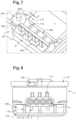
- FIG. 7 is a depiction of an elevation view of a temperature sensor according to an embodiment of the invention, without PCB installed,
- FIG. 8 is a schematic depiction of a cross-sectional view of a temperature sensor according to an embodiment of the invention, without side cover,
- FIG. 9 is a schematic depiction of a cross-sectional view of a temperature sensor according to an embodiment of the invention, with side cover,
- FIG. 10 is a depiction of an elevation view of a temperature sensor according to another embodiment of the invention, with PCB installed,
- FIG. 11 is a depiction of an elevation view of a part of a temperature sensor according to another embodiment of the invention, without PCB installed,
- FIG. 12 is a schematic depiction of a cross-sectional view of a temperature sensor according to an embodiment of the invention, without side cover,
- FIG. 13 is a schematic depiction of an elevation view from below of a temperature sensor according to an embodiment of the invention.
- FIG. 14 is complete illustration of a temperature sensor according to an embodiment of the invention.
- FIG. 1 shows the interior of a temperature sensor 1 for an engine of a vehicle according to the invention.
- a vehicle in the context of the invention means any type of terrestrial vehicle, for example a car and a truck, or aerial vehicle.
- the sensor according to the invention illustrated in FIGS. 1 , 2 and 3 comprises a casing 1 containing a circuit board 14 , also known as a PCB (printed circuit board).
- the casing 1 is traversed by at least one pair 2 of wires 3 fitted with terminals 8 and wire sleeve seals 6 , both crimped.
- the material of the casing 1 is a thermoplastic, such as for example PA66, PA6, PBT, PPS or PPA.
- the casing 1 is made of a material with a fibre content, for example 30% fibres.
- the circuit board 14 is arranged in the casing 1 and rests on several support zones 105 . These support zones are formed around studs 104 , 106 .
- the studs 104 , 106 are hot-deformed, for example by rivet heading, in order to to secure the board definitively.
- the position of the studs and their diameter are selected to ensure the robustness of the support of the board 14 , in particular under vibrations.
- the studs 104 , 106 for example each have a diameter greater than or equal to 2.5 mm.
- the studs 104 , 106 are situated between the first third and the middle of the board, in order to limit vibrations.
- the casing 1 comprises a connector 101 and at least one flange 102 for holding the terminals, with an over-moulded insert 11 .
- the connector 101 comprises at least one metal insert 10 , for example made of bronze or brass, ensuring the electrical connection with the circuit board 14 .
- the casing 1 comprises a main cover 13 .
- This cover encloses the casing 1 and thus protects the circuit board 14 from the external environment (humidity, pollution, liquid).
- This cover 13 is tightly fixed to the casing 1 by bonding, by vibration or by laser welding.
- the flange 9 is fixed to the casing 1 via the plastic deformation of at least one support stud 106 arranged in the casing 1 .
- the flange is fixed by two support studs 106 .
- the diameter of a stud 106 is greater than or equal to 1.5 mm. This ensures sufficient mechanical strength for a tensile load F of 80 N on each wire 3 .
- the stud is deformed by melting of the plastic material of the stud by heating, which is known as rivet heading.
- the stud is deformed by ultrasonic welding, for example between 20 and 30 kHz.
- Deformation by ultrasonic welding has the advantage of a short cycle time with no risk of fouling, and retains no residual play after the operation due to the shrinkage of the plastic after cooling.
- ribs 115 are provided in the casing 1 .
- the ribs 115 shown on FIG. 8 are arranged parallel to the support stud 106 , to avoid a collapse of the material of the casing 1 .
- the flange is made of a fibre-containing material, for example with a content of 45%.
- the fibre content of the flange is greater than that of the casing, thus avoiding collapse of the flange and creation of a residual play after operation.
- the material of the flange may be a thermoplastic such as PA66, PA6, PBT or PPA.
- two support zones 901 receive the melted material of the support studs 106 .
- An empty space 905 is provided between the two support zones 901 . This empty space 905 allows insertion of tooling for pressing the terminals into the base of the casing before insertion of the flange 9 . This guarantees a repeatable positioning of the terminals 8 .
- a seal is arranged in the empty space 905 formed by the flange 9 and the casing 1 .
- This seal is a mono- or bi-component epoxy resin, or a mono- or bi-component gel.
- This seal ensures complete tightness between the conductor 5 and the insulation. No humidity may thus pass via the wires 3 , by capillary action between the strands of the conductor and the insulation, as far as the measurement probes 15 . This improves the precision and robustness of the product.
- a play J 3 is provided between the ribs 115 and the base 902 of the support 901 ,
- the play J 3 is for example greater than or equal to 0.1 mm.
- the flange 9 performs two essential functions. The first is the precise and repeatable positioning of the ends of the folded terminals 802 in metallized holes provided in the circuit board 14 . The second is to guarantee the tensile strength of the terminals 8 when a force F is exerted on the wires 3 .
- the terminal 8 illustrated, for example in FIG. 4 comprises a first portion 801 formed by folding a sheet of copper alloy. This first portion of the terminal is folded after insertion in the casing 1 .
- the terminal also comprises a chamfered end 802 with coating selectively deposited over a few mm.
- the coating may be a sublayer of 0.5 to 5 ⁇ m of nickel (Ni) and a layer of 0.5 to 5 ⁇ m of tin (Sn) in order to promote brazing onto the circuit board 14 ,
- the coating is absent from the folding zone of the terminal 8 , so as to limit the risk of incipient breakage and to allow compensation for cold temperature by the material of the substrate of the terminals 8 if the latter forms a thermocouple.
- a layer of nickel (or another conductive metal) on the surface balances the electrical loads generated by the thermocouple which forms the terminals (CuFe2P/CUNi10) and hence cancels the desired compensation.
- the aim of the chamfer is to facilitate insertion of the flange 9 after folding.
- the terminal 8 consists of an axial stop ( 803 ) formed by a double fold of the sheet constituting this.
- This axial stop is designed to fix the insertion position of the terminal in its housing 110 in the casing 1 .
- a reduction in clear cross-section 114 of the housing 110 ensures this stop on the terminal 8 at the same time as promoting guidance thereof in the folding tool (not shown).
- the terminal 8 comprises a second portion 804 crimped onto the conductor 5 .
- This second portion 804 for example has a nickel coating (Ni) approximately 0.5 to 5 ⁇ m thick, to facilitate laser welding. This second portion is also called the cold junction of the thermocouple.
- the terminal also comprises a third portion 805 crimped onto a wire sleeve 6 for mechanical support thereof. Behind the sleeve, the wires 3 are arranged in pairs 2 and are protected by a sheath 7 , for example made of glass fibre and silicone. At another end of the wire pair are the temperature sensors. The temperature sensors are fixed to bosses 16 of the equipment or pipe to be measured.
- the terminal in the case of a thermocouple sensor, is made of a low alloy copper such as CuFe2P for the positive pole and a cupronickel such as CuNi10 for the negative pole.
- This copper alloy in raw form takes the form of a sheet of thickness 0.2 to 0.4 mm.
- the casing comprises a chamfer 112 to facilitate insertion of the sleeve 6 .
- the terminals 8 are inserted straight into the casing 1 then folded directly inside using a folding tool, such that no over-moulding is necessary.
- the casing 1 comprises a clear space 107 such that a tool for folding the terminals 8 can be introduced into the casing 1 . After folding, the tool is withdrawn and leaves space for the flange which will definitively secure the terminals.
- a guide play J 2 with a height h is left between the terminal 8 and the flange 9 .
- the ratio J 2 /h is minimized.
- J 2 is equal to 0.05 mm
- the height is equal to 3 mm. Minimizing this ratio promotes both desired functions.
- the terminal is folded with an angle ⁇ selected such that the terminal 8 is always in contact with the one of the sides of the flange.
- This angle is for example between 1 and 3°.
- the support zone of the flange 9 is positioned on the casing 1 below the zone 901 , so that it remains flat without pivoting.
- the play J 1 between the flange 9 and the terminals 8 is different from zero, and is for example equal to 0.05 mm.
- the zone for insertion of the terminals 8 in the flange 9 is facilitated at 904 by a chamfer on one side of the flange and a radius on the other side of the flange.
- the terminal radius R is selected sufficiently large, for example 0.9 mm for a folded thickness of 0.5 mm.
- the radius on the flange R′ lies within the radius of curvature of the terminal 8 , so as not to damage it.
- thermocouple sensor In the case of a thermocouple sensor, the air flow is supplied for example from the exterior air of the vehicle when the casing is not placed below the engine hood or in an isolated zone. In this configuration, one face of the casing is in contact with the engine between 50° C. and 150° C., and the opposite face sees a cold air flow between ⁇ 40° C. and 10° C. This gradient between the outer faces of the casing 1 generates a gradient in the casing between the cold junction of the thermocouple 804 and the circuit board 14 containing the element which measures the cold temperature.
- At least one air cavity 108 is provided between the cold junction 804 and the lower and side face of the case 1 .
- a second air cavity 109 is provided between the cold junction and the upper and side face.
- cavities 108 , 109 act as thermal insulation and allow a gain of around 10° in the temperature difference for an exterior gradient of 100° C.
- the first cavity 108 is closed by a side cover 12 so as to avoid any flow of air into this zone.
- the cover 12 is tightly fixed to the casing 1 .
- the side cover 12 is for example fixed by ultrasonic welding (20 to 30 kHz) with a rapid cycle time.
- energy vectors 1201 are provided on the inner face of the side cover 12 , and are melted and mixed with the material of the casing 1 .
- the side cover 12 is formed from the same material as the casing 1 .
- the casing 1 comprises internal ribs 117 and support zones 116 formed at the end of the wall of the casing 1 , which allows balancing of the welding over the entire periphery of the cover 12 .
- the internal ribs 117 are arranged in the lower part of the casing 1 below the cold junction 804 .
- the casing comprises at least two holes 118 formed below the casing 1 for the escape of water which could be retained in the first cavity 108 .
- the casing comprises additional ribs 111 which provide a better rigidity of the casing 1 .
- These additional ribs 111 are arranged in the upper part of the casing 1 .
- the upper and lower parts of the casing are defined with respect to the face of the casing 1 comprising the main cover 13 , which is considered to be the upper face of the sensor.
- the first cavity 108 and second cavity 109 are linked so as to form a single cavity 120 .
- This cavity 120 surrounds the cold junction 804 .
- the casing 1 also comprises internal ribs 117 and additional ribs 111 , the purpose of which is to strengthen the cold junction, and which also serve to balance the welding of the side cover 12 .
Landscapes
- Physics & Mathematics (AREA)
- General Physics & Mathematics (AREA)
- Engineering & Computer Science (AREA)
- Microelectronics & Electronic Packaging (AREA)
- Measuring Temperature Or Quantity Of Heat (AREA)
- Casings For Electric Apparatus (AREA)
Abstract
Description
-
- a casing containing a circuit board and traversed by at least one pair of wires provided with terminals, the terminal being made up of a portion crimped onto a conductor arranged in the casing,
- a connector comprising at least one metal insert ensuring the electrical connection with the circuit board,
- characterized in that the casing comprises at least one flange for holding the terminals, the terminals being folded.
-
- a first portion formed by folding a sheet of a copper alloy, this first portion of the terminal being folded after insertion in the casing,
- an axial stop formed by a double fold of the sheet constituting this,
- a second portion crimped onto the conductor,
- a third portion crimped onto a wire sleeve.
Claims (10)
Applications Claiming Priority (3)
| Application Number | Priority Date | Filing Date | Title |
|---|---|---|---|
| FR1903137A FR3094482B1 (en) | 2019-03-26 | 2019-03-26 | Protective case for vehicle temperature sensor |
| FR1903137 | 2019-03-26 | ||
| PCT/EP2020/058258 WO2020193593A1 (en) | 2019-03-26 | 2020-03-25 | Protective casing for vehicle temperature sensor |
Publications (2)
| Publication Number | Publication Date |
|---|---|
| US20220178762A1 US20220178762A1 (en) | 2022-06-09 |
| US12140481B2 true US12140481B2 (en) | 2024-11-12 |
Family
ID=68210866
Family Applications (1)
| Application Number | Title | Priority Date | Filing Date |
|---|---|---|---|
| US17/442,385 Active 2040-07-22 US12140481B2 (en) | 2019-03-26 | 2020-03-25 | Protective casing for vehicle temperature sensor |
Country Status (5)
| Country | Link |
|---|---|
| US (1) | US12140481B2 (en) |
| EP (1) | EP3949026B1 (en) |
| CN (1) | CN113632324A (en) |
| FR (1) | FR3094482B1 (en) |
| WO (1) | WO2020193593A1 (en) |
Citations (9)
| Publication number | Priority date | Publication date | Assignee | Title |
|---|---|---|---|---|
| US5482470A (en) * | 1993-05-20 | 1996-01-09 | Sumitomo Wiring Systems, Ltd. | Electrical connector |
| US5951305A (en) * | 1998-07-09 | 1999-09-14 | Tessera, Inc. | Lidless socket and method of making same |
| US20020111057A1 (en) * | 2001-02-09 | 2002-08-15 | Harting Kgaa | Plug connector, consisting of a plug-in jack and a plug part |
| US20050112956A1 (en) * | 2003-11-26 | 2005-05-26 | Yazaki Corporation | Busbar molded article, process for manufacturing the same and electronic unit |
| US7090547B2 (en) * | 2002-07-30 | 2006-08-15 | Mitsubishi Cable Industries, Ltd. | Male bar-like connection terminal and method of producing the same |
| CN202840043U (en) | 2012-08-27 | 2013-03-27 | 深圳市源丰光彩科技有限公司 | IC card seat connection device provided with flex cable |
| US8905783B2 (en) * | 2010-05-20 | 2014-12-09 | Yukita Electric Wire Co., Ltd. | Terminal box for solar cell module |
| US20150229038A1 (en) * | 2012-11-07 | 2015-08-13 | Yazaki Corporation | Male terminal |
| DE102017115976A1 (en) | 2016-07-21 | 2018-01-25 | Denso Corporation | Sensor unit and method for producing the same |
Family Cites Families (3)
| Publication number | Priority date | Publication date | Assignee | Title |
|---|---|---|---|---|
| ITTO20080483A1 (en) * | 2008-06-19 | 2009-12-20 | Eltek Spa | PRESSURE SENSOR DEVICE |
| FR3053465B1 (en) * | 2016-06-30 | 2018-08-10 | Sc2N | PROTECTIVE HOUSING FOR VEHICLE TEMPERATURE SENSOR |
| JP6512373B2 (en) * | 2016-08-23 | 2019-05-15 | 日本精工株式会社 | Terminal connection part and terminal connection structure between control device and motor using the same |
-
2019
- 2019-03-26 FR FR1903137A patent/FR3094482B1/en active Active
-
2020
- 2020-03-25 WO PCT/EP2020/058258 patent/WO2020193593A1/en not_active Ceased
- 2020-03-25 US US17/442,385 patent/US12140481B2/en active Active
- 2020-03-25 EP EP20712370.4A patent/EP3949026B1/en active Active
- 2020-03-25 CN CN202080022619.6A patent/CN113632324A/en active Pending
Patent Citations (9)
| Publication number | Priority date | Publication date | Assignee | Title |
|---|---|---|---|---|
| US5482470A (en) * | 1993-05-20 | 1996-01-09 | Sumitomo Wiring Systems, Ltd. | Electrical connector |
| US5951305A (en) * | 1998-07-09 | 1999-09-14 | Tessera, Inc. | Lidless socket and method of making same |
| US20020111057A1 (en) * | 2001-02-09 | 2002-08-15 | Harting Kgaa | Plug connector, consisting of a plug-in jack and a plug part |
| US7090547B2 (en) * | 2002-07-30 | 2006-08-15 | Mitsubishi Cable Industries, Ltd. | Male bar-like connection terminal and method of producing the same |
| US20050112956A1 (en) * | 2003-11-26 | 2005-05-26 | Yazaki Corporation | Busbar molded article, process for manufacturing the same and electronic unit |
| US8905783B2 (en) * | 2010-05-20 | 2014-12-09 | Yukita Electric Wire Co., Ltd. | Terminal box for solar cell module |
| CN202840043U (en) | 2012-08-27 | 2013-03-27 | 深圳市源丰光彩科技有限公司 | IC card seat connection device provided with flex cable |
| US20150229038A1 (en) * | 2012-11-07 | 2015-08-13 | Yazaki Corporation | Male terminal |
| DE102017115976A1 (en) | 2016-07-21 | 2018-01-25 | Denso Corporation | Sensor unit and method for producing the same |
Non-Patent Citations (1)
| Title |
|---|
| International Search Report with Written Opinion issued in corresponding International Application No. PCT/EP2020/058258, mailed Apr. 8, 2020 (14 pages). |
Also Published As
| Publication number | Publication date |
|---|---|
| EP3949026A1 (en) | 2022-02-09 |
| FR3094482A1 (en) | 2020-10-02 |
| EP3949026B1 (en) | 2023-11-08 |
| CN113632324A (en) | 2021-11-09 |
| US20220178762A1 (en) | 2022-06-09 |
| FR3094482B1 (en) | 2021-07-09 |
| WO2020193593A1 (en) | 2020-10-01 |
Similar Documents
| Publication | Publication Date | Title |
|---|---|---|
| US7553078B2 (en) | Temperature sensor and method for producing the same | |
| US6899457B2 (en) | Thermistor temperature sensor | |
| US7012502B2 (en) | Sensor and manufacturing method thereof | |
| US8806918B2 (en) | Gas sensor and manufacturing method therefor | |
| JP5484336B2 (en) | Contact module for sensors with limited structural space | |
| US20070237205A1 (en) | Temperature sensor and method of manufacturing the same | |
| KR20110130449A (en) | Sensor lead sealing and strain relief | |
| US8177427B2 (en) | Temperature sensor and method of producing the same | |
| US10989608B2 (en) | Temperature sensor | |
| WO2019087755A1 (en) | Temperature sensor and device provided with temperature sensor | |
| EP3479087B1 (en) | Protective casing for a temperature sensor in a vehicle | |
| EP2075557B1 (en) | Temperature sensor and method of producing the same | |
| KR20200101908A (en) | Thermocouple, thermocouple bonding tool, battery module, thermocouple manufacturing method, and thermocouple bonding method | |
| US12140481B2 (en) | Protective casing for vehicle temperature sensor | |
| US20170241841A1 (en) | Measurement probe comprising a sensitive element | |
| EP3382358A1 (en) | Temperature sensor | |
| JP5842610B2 (en) | Sensor control apparatus and manufacturing method thereof | |
| US20150231868A1 (en) | Method for pressing or welding the protective cover of a high temperature sensor | |
| WO2020193597A1 (en) | Protective casing for a vehicle temperature sensor | |
| US7120994B2 (en) | Apparatus for the automated manufacture of a probe tip | |
| JPH11132994A (en) | Gas measurement sensor with sealing device | |
| WO2024070405A1 (en) | Temperature sensor for busbar, busbar module and manufacturing method therefor | |
| EP3901598A1 (en) | Temperature sensor for rotating electric machine and method of manufacturing the same | |
| JP2010175257A (en) | Temperature measuring sensor | |
| JP4059222B2 (en) | Temperature sensor and method of manufacturing temperature sensor |
Legal Events
| Date | Code | Title | Description |
|---|---|---|---|
| FEPP | Fee payment procedure |
Free format text: ENTITY STATUS SET TO UNDISCOUNTED (ORIGINAL EVENT CODE: BIG.); ENTITY STATUS OF PATENT OWNER: LARGE ENTITY |
|
| AS | Assignment |
Owner name: SC2N, FRANCE Free format text: ASSIGNMENT OF ASSIGNORS INTEREST;ASSIGNORS:KOPP, GABRIEL;SERVETTAZ, AURELIEN;PRADIER, DAVID;AND OTHERS;SIGNING DATES FROM 20210927 TO 20211008;REEL/FRAME:057832/0900 |
|
| STPP | Information on status: patent application and granting procedure in general |
Free format text: DOCKETED NEW CASE - READY FOR EXAMINATION |
|
| STPP | Information on status: patent application and granting procedure in general |
Free format text: NON FINAL ACTION MAILED |
|
| STPP | Information on status: patent application and granting procedure in general |
Free format text: RESPONSE TO NON-FINAL OFFICE ACTION ENTERED AND FORWARDED TO EXAMINER |
|
| STPP | Information on status: patent application and granting procedure in general |
Free format text: NON FINAL ACTION MAILED |
|
| STPP | Information on status: patent application and granting procedure in general |
Free format text: FINAL REJECTION MAILED |
|
| STPP | Information on status: patent application and granting procedure in general |
Free format text: RESPONSE AFTER FINAL ACTION FORWARDED TO EXAMINER |
|
| STPP | Information on status: patent application and granting procedure in general |
Free format text: ADVISORY ACTION MAILED |
|
| STPP | Information on status: patent application and granting procedure in general |
Free format text: NOTICE OF ALLOWANCE MAILED -- APPLICATION RECEIVED IN OFFICE OF PUBLICATIONS |
|
| ZAAB | Notice of allowance mailed |
Free format text: ORIGINAL CODE: MN/=. |
|
| STPP | Information on status: patent application and granting procedure in general |
Free format text: PUBLICATIONS -- ISSUE FEE PAYMENT RECEIVED |
|
| STPP | Information on status: patent application and granting procedure in general |
Free format text: PUBLICATIONS -- ISSUE FEE PAYMENT VERIFIED |
|
| STCF | Information on status: patent grant |
Free format text: PATENTED CASE |