US12140159B2 - Heat dissipation system of electronic device - Google Patents
Heat dissipation system of electronic device Download PDFInfo
- Publication number
- US12140159B2 US12140159B2 US18/407,486 US202418407486A US12140159B2 US 12140159 B2 US12140159 B2 US 12140159B2 US 202418407486 A US202418407486 A US 202418407486A US 12140159 B2 US12140159 B2 US 12140159B2
- Authority
- US
- United States
- Prior art keywords
- heat dissipation
- outlet
- sub
- electronic device
- heat
- Prior art date
- Legal status (The legal status is an assumption and is not a legal conclusion. Google has not performed a legal analysis and makes no representation as to the accuracy of the status listed.)
- Active
Links
Images


Classifications
-
- F—MECHANICAL ENGINEERING; LIGHTING; HEATING; WEAPONS; BLASTING
- F04—POSITIVE - DISPLACEMENT MACHINES FOR LIQUIDS; PUMPS FOR LIQUIDS OR ELASTIC FLUIDS
- F04D—NON-POSITIVE-DISPLACEMENT PUMPS
- F04D29/00—Details, component parts, or accessories
- F04D29/40—Casings; Connections of working fluid
- F04D29/42—Casings; Connections of working fluid for radial or helico-centrifugal pumps
- F04D29/4206—Casings; Connections of working fluid for radial or helico-centrifugal pumps especially adapted for elastic fluid pumps
- F04D29/4226—Fan casings
- F04D29/4246—Fan casings comprising more than one outlet
-
- F—MECHANICAL ENGINEERING; LIGHTING; HEATING; WEAPONS; BLASTING
- F04—POSITIVE - DISPLACEMENT MACHINES FOR LIQUIDS; PUMPS FOR LIQUIDS OR ELASTIC FLUIDS
- F04D—NON-POSITIVE-DISPLACEMENT PUMPS
- F04D29/00—Details, component parts, or accessories
- F04D29/58—Cooling; Heating; Diminishing heat transfer
- F04D29/582—Cooling; Heating; Diminishing heat transfer specially adapted for elastic fluid pumps
-
- F—MECHANICAL ENGINEERING; LIGHTING; HEATING; WEAPONS; BLASTING
- F04—POSITIVE - DISPLACEMENT MACHINES FOR LIQUIDS; PUMPS FOR LIQUIDS OR ELASTIC FLUIDS
- F04D—NON-POSITIVE-DISPLACEMENT PUMPS
- F04D29/00—Details, component parts, or accessories
- F04D29/26—Rotors specially for elastic fluids
- F04D29/28—Rotors specially for elastic fluids for centrifugal or helico-centrifugal pumps for radial-flow or helico-centrifugal pumps
- F04D29/281—Rotors specially for elastic fluids for centrifugal or helico-centrifugal pumps for radial-flow or helico-centrifugal pumps for fans or blowers
-
- F—MECHANICAL ENGINEERING; LIGHTING; HEATING; WEAPONS; BLASTING
- F04—POSITIVE - DISPLACEMENT MACHINES FOR LIQUIDS; PUMPS FOR LIQUIDS OR ELASTIC FLUIDS
- F04D—NON-POSITIVE-DISPLACEMENT PUMPS
- F04D29/00—Details, component parts, or accessories
- F04D29/40—Casings; Connections of working fluid
- F04D29/42—Casings; Connections of working fluid for radial or helico-centrifugal pumps
- F04D29/4206—Casings; Connections of working fluid for radial or helico-centrifugal pumps especially adapted for elastic fluid pumps
- F04D29/4226—Fan casings
-
- G—PHYSICS
- G06—COMPUTING OR CALCULATING; COUNTING
- G06F—ELECTRIC DIGITAL DATA PROCESSING
- G06F1/00—Details not covered by groups G06F3/00 - G06F13/00 and G06F21/00
- G06F1/16—Constructional details or arrangements
- G06F1/20—Cooling means
- G06F1/203—Cooling means for portable computers, e.g. for laptops
-
- H—ELECTRICITY
- H05—ELECTRIC TECHNIQUES NOT OTHERWISE PROVIDED FOR
- H05K—PRINTED CIRCUITS; CASINGS OR CONSTRUCTIONAL DETAILS OF ELECTRIC APPARATUS; MANUFACTURE OF ASSEMBLAGES OF ELECTRICAL COMPONENTS
- H05K7/00—Constructional details common to different types of electric apparatus
- H05K7/20—Modifications to facilitate cooling, ventilating, or heating
- H05K7/20009—Modifications to facilitate cooling, ventilating, or heating using a gaseous coolant in electronic enclosures
- H05K7/20136—Forced ventilation, e.g. by fans
- H05K7/20172—Fan mounting or fan specifications
Definitions
- the disclosure is related to a heat dissipation system, in particular to a heat dissipation system of an electronic device.
- heat resistance of the system may be reduced, or performance of a heat dissipation fan inside the laptop may be improved.
- the laptop preferably has as few heat dissipation holes as possible. As a result, the heat resistance of the system increases, and further, an air intake amount of the heat dissipation fan decreases, making it difficult for air from the external environment to enter the system and produce heat convection which is necessary for heat dissipation.
- an existing centrifugal fan has large air gaps between blades.
- airflows are not easily controlled and backflows are likely to occur, resulting in insufficient wind pressure, thereby affecting heat dissipation efficiency.
- problems such as air leakage are likely to occur.
- the heat dissipation fan installed in the electronic devices is also required to be as thin as possible.
- the limited space prevents the airflows from smoothly entering the heat dissipation fan and exiting therefrom, thus affecting the heat dissipation efficiency of the heat dissipation fan.
- the disclosure provides a centrifugal heat dissipation fan and a heat dissipation system of an electronic device, wherein the centrifugal heat dissipation fan has outlets disposed in different radical directions, such that a heat dissipation system with good heat dissipation efficiency can be provided in the electronic device.
- the heat dissipation system of an electronic device of the disclosure includes a body, a plurality of heat sources disposed in the body, and at least one centrifugal heat dissipation fan disposed in the body.
- the at least one centrifugal heat dissipation fan includes a housing and an impeller.
- the housing has at least one inlet disposed along an axis and a plurality of outlets in different radial directions, and the plurality of outlets respectively correspond to the plurality of heat sources.
- the impeller is disposed in the housing along the axis.
- the centrifugal heat dissipation fan can be optimally configured in the body of the electronic device according to the positions of the heat sources. This breaks through the conventional design concept of centrifugal heat dissipation fans.
- an airflow is taken into the housing from an axial inlet and is then driven by rotation of the impeller to be discharged from different outlets.
- the outlets respectfully correspond to the heat sources and guide the desired airflows to the heat sources or an object requiring heat dissipation, thereby effectively improving heat dissipation efficiency of the centrifugal heat dissipation fan in the body.
- FIG. 1 is an exploded view of a centrifugal heat dissipation fan according to an embodiment of the disclosure.
- FIG. 2 is a top view of the centrifugal heat dissipation fan in FIG. 1 .
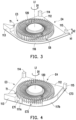
- FIGS. 3 to 6 are schematic views of centrifugal heat dissipation fans according to different embodiments of the disclosure.
- FIG. 7 and FIG. 8 are simple schematic views of heat dissipation systems of an electronic device according to different embodiments of the disclosure.
- FIG. 1 is an exploded view of a centrifugal heat dissipation fan according to an embodiment of the disclosure.
- FIG. 2 is a top view of the centrifugal heat dissipation fan in FIG. 1 . Also, some members in FIG. 1 are omitted in FIG. 2 for easily identifying an inner part of the centrifugal heat dissipation fan.
- a rectangular coordinate system X-Y-Z is provided here for facilitating the description.
- a centrifugal heat dissipation fan 100 includes a housing 110 and an impeller 120 .
- the housing 110 has at least one inlet (two inlets, E 1 and E 2 , are illustrated for exemplary purposes) disposed along an axis L 1 and a plurality of outlets disposed in different radial directions and apart from each other.
- the impeller 120 is disposed in the housing 110 along the axis L 1 . It is noted that a method for driving the centrifugal heat dissipation fan 100 (for example, rotating the centrifugal heat dissipation fan 100 by a motor connected to the impeller 120 ) is known from the related art and a description thereof is omitted in the present embodiment.
- the impeller 120 rotates in the housing 110 about the axis L 1 , airflows are generated, enter the housing 110 through the inlets E 1 and E 2 , and exit the housing 110 through the outlets in different radial directions.
- the housing 110 includes an upper cover 111 , a base 112 , and side wall structures 113 , 114 , and 115 , wherein the upper cover 111 has the inlet E 1 , the base 112 has the inlet E 2 , and the side wall structures 113 , 114 , and 115 are connected between the upper cover 111 and the base 112 so as to form the outlets in different radial directions with the upper cover 112 and the base 112 .
- the outlets disposed apart from each other are defined as a first main outlet E 3 , a second main outlet E 4 , and a sub-outlet E 5 .
- the side wall structure 113 of the housing 110 has an inner wall tongue part T 1 between and adjoining the first main outlet E 3 and the sub-outlet E 5 .
- the inner wall tongue part T 1 , the sub-outlet E 5 , the second main outlet E 4 , and the first main outlet E 3 adjoin each other in sequence in a counterclockwise loop configuration.
- first main outlet E 3 and the second main outlet E 4 are each a planar outlet, and the sub-outlet E 5 is an arc outlet. Furthermore, a sum of an area A 3 of the first main outlet E 3 and an area A 4 of the second main outlet E 4 is greater than an area A 5 of the sub-outlet E 5 (A 3 +A 4 >A 5 ), wherein an air-out radial direction R 1 of the first main outlet E 3 and an air-out radial direction R 2 of the second main outlet E 4 orthogonally intersect each other. As shown in FIG.
- the air-out radial direction R 1 is substantially a negative Y-axis direction
- the air-out radial direction R 2 is substantially a negative X-axis direction
- an air-out direction of the sub-outlet E 5 includes different radial directions.
- the sub-outlet E 5 has, at a start point ST (that is, the inner wall tongue part T 1 serves as the start point of the sub-outlet E 5 ), an air-out radial direction R 3 which is substantially a positive X-axis direction, and has, at an end point EN, an air-out radial direction R 4 which is substantially a positive Y-axis direction.
- the sub-outlet E 5 substantially covers a circumferential angle of 90 degrees. That is to say, the side wall structure 113 and the side wall structure 115 are substantially taken respectively as the start point and the end point of the range of the sub-outlet E 5 of the centrifugal heat dissipation fan 100 in the present embodiment.
- the sub-outlet E 5 is further formed on the arc side surface of the housing 10 .
- the housing 110 in the presence of the first main outlet E 3 and the second main outlet E 4 , the sub-outlet E 5 is further formed on the arc side surface of the housing 10 .
- external airflows can be continuously taken into the housing 110 from the inlets E 1 and E 2 during continuous rotation of the impeller 120 thanks to the characteristics of the centrifugal heat dissipation fan 100 of taking in the air axially and outputting the air radially. Therefore, the overall air output amount of the centrifugal heat dissipation fan 100 is effectively increased.
- FIGS. 3 to 6 are schematic views of centrifugal heat dissipation fans according to different embodiments of the disclosure, wherein the same structures as those in the aforementioned embodiment are denoted by the same reference numerals and descriptions thereof will not be repeated.
- an orthographic projection dimension of a sub-outlet E 6 on the axis L 1 is less than an orthographic projection dimension of the housing on the axis L 1 , that is, a side wall structure 116 is further connected between the side wall structure 113 and the side wall structure 115 .
- an axial dimension h 1 of the side wall structure 116 along the axis L 1 is less than an axial dimension h 2 of the housing along the axis L 1 , which results in that the sub-outlet E 6 is substantially smaller than the sub-outlet E 5 of the aforementioned embodiment.
- electronic components have either a planar design or a planar layered design, and the sub-outlet E 6 can be used to guide a heat dissipation airflow to a desired position in accordance with the aforementioned layered design.
- the sub-outlet E 6 can be targeted at the heat source that requires heat dissipation. Meanwhile, due to the presence of the side wall structure 116 , some airflows can be kept inside the housing and continuously compressed by the impeller 120 and the side wall structure 116 , so that a certain wind pressure is maintained at the following second main outlet E 4 and first main outlet E 3 .
- the housing of the present embodiment has a plurality of sub-outlets E 71 , E 72 , and E 73 disposed in different radial directions and apart from each other. That is, side wall structures 117 a and 117 b are additionally disposed between the side wall structure 113 and the side wall structure 115 to form sub-outlets E 71 , E 72 , and E 73 at desired positions.
- the positions, opening dimensions and numbers of the sub-outlets E 71 , E 72 , and E 73 are not limited, and may be appropriately adjusted according to the requirements of the heat dissipation system of an electronic device.
- FIG. 5 shows an embodiment similar to that shown in FIG.
- sub-outlets E 81 , E 82 , E 83 , E 84 , and E 85 are disposed in different radial directions and have different opening profiles.
- the opening profiles in the present embodiment are not limited and may be appropriately adjusted according to the requirements of the heat dissipation system.
- guide structures 118 a , 118 b , 118 c , 118 d , and 118 e are disposed respectively next to the sub-outlets E 91 , E 92 , E 93 , E 94 , E 95 , and E 96 , and extend away from the axis L 1 (that is, extend in a direction away from the axis L 1 .
- FIG. 7 and FIG. 8 are simple schematic views of heat dissipation systems of an electronic device according to different embodiments of the disclosure. It is noted that in a body 20 of the electronic device, electronic components have either a planar design or a planar layered design. Therefore, a centrifugal heat dissipation fan that outputs air radially is suitable for performing heat dissipation on the electronic device.
- the heat dissipation systems shown in FIG. 7 and FIG. 8 may both use the centrifugal heat dissipation fans of the different embodiments mentioned above according to requirements.
- the heat dissipation system of an electronic device in the present embodiment includes the body 20 , heat sources 21 and 22 disposed in the body 20 , and a centrifugal heat dissipation fan 100 A disposed in the body 20 .
- the first main outlet E 3 , the second main outlet E 4 , and a sub-outlet E 51 of the centrifugal heat dissipation fan 100 A respectively correspond to the heat sources 21 and 22 that are different from each other.
- the heat source 21 in the present embodiment includes an electronic chip 21 a , a heat conduction element 21 b and a heat dissipation fin 21 c .
- the heat conduction element 21 b is connected between the electronic chip 21 a and the heat dissipation fin 21 c so that the electronic chip 21 a transfers heat to the heat dissipation fin 21 c through the heat conduction element 21 b .
- the second main outlet E 4 of the centrifugal heat dissipation fan 100 A corresponds to the heat dissipation fin 21 c
- the sub-outlet E 51 corresponds to the electronic chip 21 a .
- the heat source 22 in the present embodiment includes an electronic chip 22 a , a heat conduction element 22 b , and a heat dissipation fin 22 c .
- the heat conduction element 22 b is connected between the electronic chip 22 a and the heat dissipation fin 22 c so that the electronic chip 22 a transfers heat to the heat dissipation fin 22 c through the heat conduction element 22 b .
- the first main outlet E 3 of the centrifugal heat dissipation fan 100 A corresponds to the heat dissipation fin 22 c
- the sub-outlet E 51 of the centrifugal heat dissipation fan 100 A corresponds to the electronic chip 22 a .
- the electronic chips 21 a and 22 a are disposed inside the body 20
- the heat dissipation fins 21 c and 22 c are disposed at edges inside the body 20 . Therefore, by the first main outlet E 3 , the second main outlet E 4 and the sub-outlet E 5 in different radial directions, the centrifugal heat dissipation fan 100 A performs inward heat dissipation on the heat dissipation electronic chips 21 a and 22 a and outward heat dissipation on the heat dissipation fins 21 c and 22 c at the same time.
- the heat conduction elements 21 b and 22 b are exemplified by heat pipes, and in another embodiment not shown, they may be vapor chambers.
- the heat dissipation system of an electronic device in the present embodiment includes the body 20 , the heat sources 21 and 22 disposed in the body 20 , and the centrifugal heat dissipation fan 100 A and a centrifugal heat dissipation fan 100 B disposed in the body 20 .
- two centrifugal heat dissipation fans namely 100 A and 100 B, simultaneously dissipate heat from a plurality of heat sources.
- the heat sources 21 and 22 are the same as those in the aforementioned embodiments.
- a heat dissipation fin 23 is added in the present embodiment.
- the centrifugal heat dissipation fan 100 A faces outward of the body 20 and dissipates heat from the heat dissipation fins 21 c and 23 at the same time
- the centrifugal heat dissipation fan 100 B faces outward of the body 20 and dissipates heat from the heat dissipation fins 21 c and 23 at the same time.
- the centrifugal heat dissipation fans 100 A and 100 B respectively provide heat dissipation airflows from two opposite sides of the electronic chips 21 a and 22 a , and the heat dissipation airflows, after converging, flow outward of the body 20 to dissipate heat from the heat dissipation fin 23 .
- the present embodiment is a further configured heat dissipation system by having two centrifugal heat dissipation fans 100 A and 100 B.
- the centrifugal heat dissipation fan since the housing of the centrifugal heat dissipation fan has the outlets in different radial directions, the centrifugal heat dissipation fan can be optimally configured in the body of the electronic device according to the positions of the heat sources. This breaks through the conventional design concept of centrifugal heat dissipation fans. In addition, an airflow is taken into the housing from an axial inlet and is then driven by rotation of the impeller to be discharged from different outlets.
- the outlets respectfully correspond to the heat sources and guide the desired airflows to the heat sources or an object requiring heat dissipation, thereby making it easy to design a heat dissipation system and effectively improving heat dissipation efficiency of the centrifugal heat dissipation fan in the body.
Landscapes
- Engineering & Computer Science (AREA)
- General Engineering & Computer Science (AREA)
- Mechanical Engineering (AREA)
- Physics & Mathematics (AREA)
- Thermal Sciences (AREA)
- Microelectronics & Electronic Packaging (AREA)
- Theoretical Computer Science (AREA)
- Computer Hardware Design (AREA)
- Human Computer Interaction (AREA)
- General Physics & Mathematics (AREA)
- Cooling Or The Like Of Electrical Apparatus (AREA)
Abstract
A heat dissipation system of an electronic device including a body, a plurality of heat sources disposed in the body, and at least one centrifugal heat dissipation fan disposed in the body is provided. The centrifugal heat dissipation fan includes a housing and an impeller disposed in the housing on an axis. The housing has at least one inlet on the axis and has a plurality of outlets in different radial directions, and the plurality of outlets respectively correspond to the plurality of heat sources.
Description
This is a divisional application of patent application Ser. No. 17/223,018, filed on Apr. 6, 2021, which claims the priority benefit of Taiwan application serial no. 109112344, filed on Apr. 13, 2020. The entirety of each of the above-mentioned patent applications is hereby incorporated by reference herein and made a part of this specification.
The disclosure is related to a heat dissipation system, in particular to a heat dissipation system of an electronic device.
Generally, to improve heat dissipation in a laptop, heat resistance of the system may be reduced, or performance of a heat dissipation fan inside the laptop may be improved. However, with the trend toward light weight and slim shape, the laptop preferably has as few heat dissipation holes as possible. As a result, the heat resistance of the system increases, and further, an air intake amount of the heat dissipation fan decreases, making it difficult for air from the external environment to enter the system and produce heat convection which is necessary for heat dissipation.
Meanwhile, an existing centrifugal fan has large air gaps between blades. Thus, airflows are not easily controlled and backflows are likely to occur, resulting in insufficient wind pressure, thereby affecting heat dissipation efficiency. Moreover, in the case of enlarging an air inlet to increase the air intake amount, if the blades of the centrifugal fan are not provided with a corresponding structure, problems such as air leakage are likely to occur.
In addition, since lighter and thinner electronic devices (such as laptops or tablets) have gradually become a trend, in view of limited internal space, the heat dissipation fan installed in the electronic devices is also required to be as thin as possible. As a result, the limited space prevents the airflows from smoothly entering the heat dissipation fan and exiting therefrom, thus affecting the heat dissipation efficiency of the heat dissipation fan.
Based on the above, a means of effectively improving at least one of the wind pressure and the air intake amount of the heat dissipation fan in the presence of the heat resistance of the system is desired to solve the aforementioned problem.
The disclosure provides a centrifugal heat dissipation fan and a heat dissipation system of an electronic device, wherein the centrifugal heat dissipation fan has outlets disposed in different radical directions, such that a heat dissipation system with good heat dissipation efficiency can be provided in the electronic device.
The heat dissipation system of an electronic device of the disclosure includes a body, a plurality of heat sources disposed in the body, and at least one centrifugal heat dissipation fan disposed in the body. The at least one centrifugal heat dissipation fan includes a housing and an impeller. The housing has at least one inlet disposed along an axis and a plurality of outlets in different radial directions, and the plurality of outlets respectively correspond to the plurality of heat sources. The impeller is disposed in the housing along the axis.
Based on the above, since the housing of the centrifugal heat dissipation fan has the outlets in different radial directions, the centrifugal heat dissipation fan can be optimally configured in the body of the electronic device according to the positions of the heat sources. This breaks through the conventional design concept of centrifugal heat dissipation fans. In addition, an airflow is taken into the housing from an axial inlet and is then driven by rotation of the impeller to be discharged from different outlets. The outlets respectfully correspond to the heat sources and guide the desired airflows to the heat sources or an object requiring heat dissipation, thereby effectively improving heat dissipation efficiency of the centrifugal heat dissipation fan in the body.
In the present embodiment, the housing 110 includes an upper cover 111, a base 112, and side wall structures 113, 114, and 115, wherein the upper cover 111 has the inlet E1, the base 112 has the inlet E2, and the side wall structures 113, 114, and 115 are connected between the upper cover 111 and the base 112 so as to form the outlets in different radial directions with the upper cover 112 and the base 112. Here, the outlets disposed apart from each other are defined as a first main outlet E3, a second main outlet E4, and a sub-outlet E5. The side wall structure 113 of the housing 110 has an inner wall tongue part T1 between and adjoining the first main outlet E3 and the sub-outlet E5. Thus, along a rotation direction D1 of the impeller 120, the inner wall tongue part T1, the sub-outlet E5, the second main outlet E4, and the first main outlet E3 adjoin each other in sequence in a counterclockwise loop configuration.
Moreover, the first main outlet E3 and the second main outlet E4 are each a planar outlet, and the sub-outlet E5 is an arc outlet. Furthermore, a sum of an area A3 of the first main outlet E3 and an area A4 of the second main outlet E4 is greater than an area A5 of the sub-outlet E5 (A3+A4>A5), wherein an air-out radial direction R1 of the first main outlet E3 and an air-out radial direction R2 of the second main outlet E4 orthogonally intersect each other. As shown in FIG. 2 , the air-out radial direction R1 is substantially a negative Y-axis direction, the air-out radial direction R2 is substantially a negative X-axis direction, and an air-out direction of the sub-outlet E5 includes different radial directions. In other words, in the present embodiment, the sub-outlet E5 has, at a start point ST (that is, the inner wall tongue part T1 serves as the start point of the sub-outlet E5), an air-out radial direction R3 which is substantially a positive X-axis direction, and has, at an end point EN, an air-out radial direction R4 which is substantially a positive Y-axis direction. Accordingly, the sub-outlet E5 substantially covers a circumferential angle of 90 degrees. That is to say, the side wall structure 113 and the side wall structure 115 are substantially taken respectively as the start point and the end point of the range of the sub-outlet E5 of the centrifugal heat dissipation fan 100 in the present embodiment.
Based on the above, according to the above configuration of the housing 110, in the presence of the first main outlet E3 and the second main outlet E4, the sub-outlet E5 is further formed on the arc side surface of the housing 10. In this way, not only an additional guide path is provided for a heat dissipation airflow, but external airflows can be continuously taken into the housing 110 from the inlets E1 and E2 during continuous rotation of the impeller 120 thanks to the characteristics of the centrifugal heat dissipation fan 100 of taking in the air axially and outputting the air radially. Therefore, the overall air output amount of the centrifugal heat dissipation fan 100 is effectively increased.
Next, referring to FIG. 4 , the housing of the present embodiment has a plurality of sub-outlets E71, E72, and E73 disposed in different radial directions and apart from each other. That is, side wall structures 117 a and 117 b are additionally disposed between the side wall structure 113 and the side wall structure 115 to form sub-outlets E71, E72, and E73 at desired positions. Here, the positions, opening dimensions and numbers of the sub-outlets E71, E72, and E73 are not limited, and may be appropriately adjusted according to the requirements of the heat dissipation system of an electronic device. FIG. 5 shows an embodiment similar to that shown in FIG. 4 , where sub-outlets E81, E82, E83, E84, and E85 are disposed in different radial directions and have different opening profiles. Similarly, the opening profiles in the present embodiment are not limited and may be appropriately adjusted according to the requirements of the heat dissipation system.
Next, referring to FIG. 6 , in the present embodiment, in addition to sub-outlets E91, E92, E93, E94, E95, and E96 that are formed different from each other, guide structures 118 a, 118 b, 118 c, 118 d, and 118 e are disposed respectively next to the sub-outlets E91, E92, E93, E94, E95, and E96, and extend away from the axis L1 (that is, extend in a direction away from the axis L1. In this way, airflows discharged from the sub-outlets E91, E92, E93, E94, E95, and E96 can be guided by the guide structures 118 a, 118 b, 118 c, 118 d, and 118 e to the corresponding heat sources requiring heat dissipation.
Referring to FIG. 7 first, the heat dissipation system of an electronic device in the present embodiment includes the body 20, heat sources 21 and 22 disposed in the body 20, and a centrifugal heat dissipation fan 100A disposed in the body 20. The first main outlet E3, the second main outlet E4, and a sub-outlet E51 of the centrifugal heat dissipation fan 100A respectively correspond to the heat sources 21 and 22 that are different from each other.
Moreover, the heat source 21 in the present embodiment includes an electronic chip 21 a, a heat conduction element 21 b and a heat dissipation fin 21 c. The heat conduction element 21 b is connected between the electronic chip 21 a and the heat dissipation fin 21 c so that the electronic chip 21 a transfers heat to the heat dissipation fin 21 c through the heat conduction element 21 b. Furthermore, the second main outlet E4 of the centrifugal heat dissipation fan 100A corresponds to the heat dissipation fin 21 c, and the sub-outlet E51 corresponds to the electronic chip 21 a. The heat source 22 in the present embodiment includes an electronic chip 22 a, a heat conduction element 22 b, and a heat dissipation fin 22 c. The heat conduction element 22 b is connected between the electronic chip 22 a and the heat dissipation fin 22 c so that the electronic chip 22 a transfers heat to the heat dissipation fin 22 c through the heat conduction element 22 b. The first main outlet E3 of the centrifugal heat dissipation fan 100A corresponds to the heat dissipation fin 22 c, and the sub-outlet E51 of the centrifugal heat dissipation fan 100A corresponds to the electronic chip 22 a. Accordingly, the electronic chips 21 a and 22 a are disposed inside the body 20, the heat dissipation fins 21 c and 22 c are disposed at edges inside the body 20. Therefore, by the first main outlet E3, the second main outlet E4 and the sub-outlet E5 in different radial directions, the centrifugal heat dissipation fan 100A performs inward heat dissipation on the heat dissipation electronic chips 21 a and 22 a and outward heat dissipation on the heat dissipation fins 21 c and 22 c at the same time.
Here, the heat conduction elements 21 b and 22 b are exemplified by heat pipes, and in another embodiment not shown, they may be vapor chambers.
Referring to FIG. 8 , the heat dissipation system of an electronic device in the present embodiment includes the body 20, the heat sources 21 and 22 disposed in the body 20, and the centrifugal heat dissipation fan 100A and a centrifugal heat dissipation fan 100B disposed in the body 20. Unlike the aforementioned embodiments, in the present embodiment, two centrifugal heat dissipation fans, namely 100A and 100B, simultaneously dissipate heat from a plurality of heat sources. The heat sources 21 and 22 are the same as those in the aforementioned embodiments. However, a heat dissipation fin 23 is added in the present embodiment. Therefore, the centrifugal heat dissipation fan 100A faces outward of the body 20 and dissipates heat from the heat dissipation fins 21 c and 23 at the same time, and the centrifugal heat dissipation fan 100B faces outward of the body 20 and dissipates heat from the heat dissipation fins 21 c and 23 at the same time. In the meantime, the centrifugal heat dissipation fans 100A and 100B respectively provide heat dissipation airflows from two opposite sides of the electronic chips 21 a and 22 a, and the heat dissipation airflows, after converging, flow outward of the body 20 to dissipate heat from the heat dissipation fin 23. In other words, the present embodiment is a further configured heat dissipation system by having two centrifugal heat dissipation fans 100A and 100B.
In summary, in the aforementioned embodiments of the disclosure, since the housing of the centrifugal heat dissipation fan has the outlets in different radial directions, the centrifugal heat dissipation fan can be optimally configured in the body of the electronic device according to the positions of the heat sources. This breaks through the conventional design concept of centrifugal heat dissipation fans. In addition, an airflow is taken into the housing from an axial inlet and is then driven by rotation of the impeller to be discharged from different outlets. The outlets respectfully correspond to the heat sources and guide the desired airflows to the heat sources or an object requiring heat dissipation, thereby making it easy to design a heat dissipation system and effectively improving heat dissipation efficiency of the centrifugal heat dissipation fan in the body.
Claims (8)
1. A heat dissipation system of an electronic device, comprising: a body; a plurality of heat sources disposed in the body; at least one centrifugal heat dissipation fan disposed in the body and comprising: a housing having at least one inlet disposed along an axis and a plurality of outlets in different radial directions, wherein the plurality of outlets respectively correspond to the plurality of heat sources; and an impeller disposed in the housing along the axis;
wherein the plurality of heat sources comprise at least one electronic chip, at least one heat conduction element, and at least one heat dissipation fin, the at least one electronic chip transfers heat to the at least one heat dissipation fin through the at least one heat conduction element, and the plurality of outlets respectively correspond to the at least one electronic chip, the at least one heat conduction element, or the at least one heat dissipation fin; and
wherein the at least one electronic chip is disposed in the body, the at least one heat dissipation fin is disposed at an edge inside the body, some of the plurality of outlets face inward of the body to correspond to the at least one electronic chip, and others of the plurality of outlets face outward of the body to correspond to the at least one heat dissipation fin.
2. The heat dissipation system of an electronic device of claim 1 , wherein the housing has a first main outlet, a second main outlet, at least one sub-outlet and an inner wall tongue part disposed apart from each other, the inner wall tongue is between and adjoins the first main outlet and the at least one sub-outlet, and along a rotation direction of the impeller, the inner wall tongue part, the at least one sub-outlet, the second main outlet, and the first main outlet adjoin each other in sequence in a loop configuration.
3. The heat dissipation system of an electronic device of claim 2 , wherein the first main outlet and the second main outlet are each a planar outlet, and the at least one sub-outlet is an arc outlet.
4. The heat dissipation system of an electronic device of claim 2 , wherein a sum of an area of the first main outlet and an area of the second main outlet is greater than an area of the at least one sub-outlet.
5. The heat dissipation system of an electronic device of claim 2 , wherein an air-out radial direction of the first main outlet and an air-out radial direction of the second main outlet orthogonally intersect each other.
6. The heat dissipation system of an electronic device of claim 2 , wherein an orthographic projection dimension of the at least one sub-outlet on the axis is less than an orthographic projection dimension of the housing on the axis.
7. The heat dissipation system of an electronic device of claim 2 , wherein the housing has a plurality of sub-outlets in different radial directions.
8. The heat dissipation system of an electronic device of claim 2 , wherein the housing further has at least one guide structure disposed at the at least one sub-outlet and extending away from the axis.
Priority Applications (1)
| Application Number | Priority Date | Filing Date | Title |
|---|---|---|---|
| US18/407,486 US12140159B2 (en) | 2020-04-13 | 2024-01-09 | Heat dissipation system of electronic device |
Applications Claiming Priority (4)
| Application Number | Priority Date | Filing Date | Title |
|---|---|---|---|
| TW109112344A TWI745928B (en) | 2020-04-13 | 2020-04-13 | Centrifugal heat dissipation fan and heat dissipation system of electronic device |
| TW109112344 | 2020-04-13 | ||
| US17/223,018 US11913472B2 (en) | 2020-04-13 | 2021-04-06 | Centrifugal heat dissipation fan and heat dissipation system of electronic device |
| US18/407,486 US12140159B2 (en) | 2020-04-13 | 2024-01-09 | Heat dissipation system of electronic device |
Related Parent Applications (1)
| Application Number | Title | Priority Date | Filing Date |
|---|---|---|---|
| US17/223,018 Division US11913472B2 (en) | 2020-04-13 | 2021-04-06 | Centrifugal heat dissipation fan and heat dissipation system of electronic device |
Publications (2)
| Publication Number | Publication Date |
|---|---|
| US20240141922A1 US20240141922A1 (en) | 2024-05-02 |
| US12140159B2 true US12140159B2 (en) | 2024-11-12 |
Family
ID=78006110
Family Applications (2)
| Application Number | Title | Priority Date | Filing Date |
|---|---|---|---|
| US17/223,018 Active US11913472B2 (en) | 2020-04-13 | 2021-04-06 | Centrifugal heat dissipation fan and heat dissipation system of electronic device |
| US18/407,486 Active US12140159B2 (en) | 2020-04-13 | 2024-01-09 | Heat dissipation system of electronic device |
Family Applications Before (1)
| Application Number | Title | Priority Date | Filing Date |
|---|---|---|---|
| US17/223,018 Active US11913472B2 (en) | 2020-04-13 | 2021-04-06 | Centrifugal heat dissipation fan and heat dissipation system of electronic device |
Country Status (2)
| Country | Link |
|---|---|
| US (2) | US11913472B2 (en) |
| TW (1) | TWI745928B (en) |
Cited By (1)
| Publication number | Priority date | Publication date | Assignee | Title |
|---|---|---|---|---|
| US12346176B2 (en) * | 2023-04-11 | 2025-07-01 | Dell Products L.P. | Thermal management apparatus for an information handling system |
Families Citing this family (7)
| Publication number | Priority date | Publication date | Assignee | Title |
|---|---|---|---|---|
| TWI816999B (en) * | 2020-04-10 | 2023-10-01 | 宏碁股份有限公司 | Centrifugal heat dissipation fan and heat dissipation system of electronic device |
| CN113294383A (en) * | 2021-07-02 | 2021-08-24 | 深圳兴奇宏科技有限公司 | Fan outer frame structure |
| CN113565796A (en) * | 2021-07-02 | 2021-10-29 | 深圳兴奇宏科技有限公司 | Centrifugal fan frame structure |
| CN114458616B (en) * | 2022-02-28 | 2023-01-06 | 联想(北京)有限公司 | Heat radiation fan |
| TWI812154B (en) | 2022-04-11 | 2023-08-11 | 宏碁股份有限公司 | Graphics card and computer host |
| CN116048194B (en) * | 2022-07-07 | 2024-03-19 | 荣耀终端有限公司 | Notebook computer |
| TWI872767B (en) * | 2023-10-31 | 2025-02-11 | 技嘉科技股份有限公司 | Fan assembly, heat dissipation assembly and electronic device |
Citations (2)
| Publication number | Priority date | Publication date | Assignee | Title |
|---|---|---|---|---|
| US6778390B2 (en) * | 2001-05-15 | 2004-08-17 | Nvidia Corporation | High-performance heat sink for printed circuit boards |
| US20080019827A1 (en) * | 2006-07-21 | 2008-01-24 | Matsushita Electric Industrial Co., Ltd. | Centrifugal fan device and eletronic device having the same |
Family Cites Families (14)
| Publication number | Priority date | Publication date | Assignee | Title |
|---|---|---|---|---|
| CN2305507Y (en) | 1997-05-29 | 1999-01-27 | 山富机械厂有限公司 | Centrifugal multi-outlet exhaust fan |
| JP3994948B2 (en) * | 2003-09-16 | 2007-10-24 | ソニー株式会社 | Cooling device and electronic equipment |
| TWM249103U (en) * | 2003-12-05 | 2004-11-01 | Forcecon Technology Co Ltd | Improved configuration structure for heat sink module and thermo conductive pipe |
| US20060078423A1 (en) * | 2004-10-08 | 2006-04-13 | Nonlinear Tech, Inc. | Bi-directional Blowers for Cooling Laptop Computers |
| TWI305574B (en) * | 2006-10-27 | 2009-01-21 | Foxconn Tech Co Ltd | Fin assembly and heat dissipation device with such fin assembly |
| CN100529426C (en) | 2006-11-17 | 2009-08-19 | 富准精密工业(深圳)有限公司 | Centrifugal fan, heat-radiation module using same and electronic device using the heat radiation module |
| CN100529413C (en) | 2006-11-17 | 2009-08-19 | 富准精密工业(深圳)有限公司 | Centrifugal fan, heat radiation device possessing the centrifugal fan and electronic device using the heat radiation device |
| TWI318341B (en) * | 2006-11-27 | 2009-12-11 | Foxconn Tech Co Ltd | Centrifugal blower, thermal module having the centrifugal blower and electronic assembly incorporating the thermal module |
| CN101282629B (en) | 2007-04-06 | 2010-05-26 | 富准精密工业(深圳)有限公司 | Cooling device |
| CN101994708A (en) | 2009-08-17 | 2011-03-30 | 神基科技股份有限公司 | Airflow generating device and cooling device |
| CN103104555B (en) | 2011-11-09 | 2015-10-28 | 台达电子工业股份有限公司 | Centrifugal fan |
| CN103115023A (en) * | 2011-11-16 | 2013-05-22 | 鸿富锦精密工业(深圳)有限公司 | Air blower |
| US10584717B1 (en) | 2019-04-25 | 2020-03-10 | Dell Products, Lp | Blower system with dual opposite outlets and fan diameter approaching to blower housing dimension for information handling systems |
| US11028857B2 (en) * | 2019-09-18 | 2021-06-08 | Dell Products, Lp | Cooling module with blower system having opposite, blower and impeller outlets for information handling systems |
-
2020
- 2020-04-13 TW TW109112344A patent/TWI745928B/en active
-
2021
- 2021-04-06 US US17/223,018 patent/US11913472B2/en active Active
-
2024
- 2024-01-09 US US18/407,486 patent/US12140159B2/en active Active
Patent Citations (2)
| Publication number | Priority date | Publication date | Assignee | Title |
|---|---|---|---|---|
| US6778390B2 (en) * | 2001-05-15 | 2004-08-17 | Nvidia Corporation | High-performance heat sink for printed circuit boards |
| US20080019827A1 (en) * | 2006-07-21 | 2008-01-24 | Matsushita Electric Industrial Co., Ltd. | Centrifugal fan device and eletronic device having the same |
Cited By (1)
| Publication number | Priority date | Publication date | Assignee | Title |
|---|---|---|---|---|
| US12346176B2 (en) * | 2023-04-11 | 2025-07-01 | Dell Products L.P. | Thermal management apparatus for an information handling system |
Also Published As
| Publication number | Publication date |
|---|---|
| US20240141922A1 (en) | 2024-05-02 |
| US20210317844A1 (en) | 2021-10-14 |
| TW202138683A (en) | 2021-10-16 |
| US11913472B2 (en) | 2024-02-27 |
| TWI745928B (en) | 2021-11-11 |
Similar Documents
| Publication | Publication Date | Title |
|---|---|---|
| US12140159B2 (en) | Heat dissipation system of electronic device | |
| US20230301017A1 (en) | Centrifugal heat dissipation fan and heat dissipation system of electronic device | |
| US11775034B2 (en) | Heat dissipation system of portable electronic device | |
| EP3106667B1 (en) | Centrifugal fan with dual outlets in the same direction and fan frame thereof | |
| US9382919B2 (en) | Fan blade structure | |
| JP3690658B2 (en) | Heat sink, cooling member, semiconductor substrate cooling apparatus, computer, and heat dissipation method | |
| US9206813B2 (en) | Centrifugal fan | |
| CN107023499B (en) | Fan and heat dissipation device | |
| US7520314B2 (en) | Heat dissipation apparatus | |
| US20200159296A1 (en) | Electronic device | |
| US11629725B2 (en) | Centrifugal heat dissipation fan | |
| US8014149B2 (en) | Fan module for electronic device | |
| US7434610B2 (en) | Heat dissipation apparatus | |
| US8011423B2 (en) | Heat sink with a centrifugal fan having vertically layered fins | |
| US12035503B2 (en) | Heat dissipation system of portable electronic device | |
| US7192249B2 (en) | Turbulent flow blower | |
| CN113672058A (en) | Centrifugal cooling fan and cooling system of electronic device | |
| CN113534927B (en) | Centrifugal cooling fan and cooling system of electronic device | |
| CN2466700Y (en) | Side air intake cooling components | |
| US12448984B2 (en) | Centrifugal fan | |
| US12104603B2 (en) | Centrifugal heat dissipation fan | |
| TW202115526A (en) | Electronic device |
Legal Events
| Date | Code | Title | Description |
|---|---|---|---|
| FEPP | Fee payment procedure |
Free format text: ENTITY STATUS SET TO UNDISCOUNTED (ORIGINAL EVENT CODE: BIG.); ENTITY STATUS OF PATENT OWNER: LARGE ENTITY |
|
| STPP | Information on status: patent application and granting procedure in general |
Free format text: DOCKETED NEW CASE - READY FOR EXAMINATION |
|
| STPP | Information on status: patent application and granting procedure in general |
Free format text: NOTICE OF ALLOWANCE MAILED -- APPLICATION RECEIVED IN OFFICE OF PUBLICATIONS |
|
| STPP | Information on status: patent application and granting procedure in general |
Free format text: PUBLICATIONS -- ISSUE FEE PAYMENT RECEIVED |
|
| STPP | Information on status: patent application and granting procedure in general |
Free format text: PUBLICATIONS -- ISSUE FEE PAYMENT VERIFIED |
|
| STCF | Information on status: patent grant |
Free format text: PATENTED CASE |