US12130002B2 - Automobile display device - Google Patents

Automobile display device Download PDF

Info

Publication number
US12130002B2
US12130002B2 US18/433,490 US202418433490A US12130002B2 US 12130002 B2 US12130002 B2 US 12130002B2 US 202418433490 A US202418433490 A US 202418433490A US 12130002 B2 US12130002 B2 US 12130002B2
Authority
US
United States
Prior art keywords
transmitting member
display portion
light
transmitting
display device
Prior art date
Legal status (The legal status is an assumption and is not a legal conclusion. Google has not performed a legal analysis and makes no representation as to the accuracy of the status listed.)
Active
Application number
US18/433,490
Other versions
US20240288145A1 (en
Inventor
Takashi Niwa
Current Assignee (The listed assignees may be inaccurate. Google has not performed a legal analysis and makes no representation or warranty as to the accuracy of the list.)
Toyota Motor Corp
Original Assignee
Toyota Motor Corp
Priority date (The priority date is an assumption and is not a legal conclusion. Google has not performed a legal analysis and makes no representation as to the accuracy of the date listed.)
Filing date
Publication date
Application filed by Toyota Motor Corp filed Critical Toyota Motor Corp
Assigned to TOYOTA JIDOSHA KABUSHIKI KAISHA reassignment TOYOTA JIDOSHA KABUSHIKI KAISHA ASSIGNMENT OF ASSIGNORS INTEREST (SEE DOCUMENT FOR DETAILS). Assignors: NIWA, TAKASHI
Publication of US20240288145A1 publication Critical patent/US20240288145A1/en
Application granted granted Critical
Publication of US12130002B2 publication Critical patent/US12130002B2/en
Active legal-status Critical Current
Anticipated expiration legal-status Critical

Links

Images

Classifications

    • BPERFORMING OPERATIONS; TRANSPORTING
    • B60VEHICLES IN GENERAL
    • B60KARRANGEMENT OR MOUNTING OF PROPULSION UNITS OR OF TRANSMISSIONS IN VEHICLES; ARRANGEMENT OR MOUNTING OF PLURAL DIVERSE PRIME-MOVERS IN VEHICLES; AUXILIARY DRIVES FOR VEHICLES; INSTRUMENTATION OR DASHBOARDS FOR VEHICLES; ARRANGEMENTS IN CONNECTION WITH COOLING, AIR INTAKE, GAS EXHAUST OR FUEL SUPPLY OF PROPULSION UNITS IN VEHICLES
    • B60K35/00Instruments specially adapted for vehicles; Arrangement of instruments in or on vehicles
    • B60K35/20Output arrangements, i.e. from vehicle to user, associated with vehicle functions or specially adapted therefor
    • B60K35/21Output arrangements, i.e. from vehicle to user, associated with vehicle functions or specially adapted therefor using visual output, e.g. blinking lights or matrix displays
    • FMECHANICAL ENGINEERING; LIGHTING; HEATING; WEAPONS; BLASTING
    • F21LIGHTING
    • F21VFUNCTIONAL FEATURES OR DETAILS OF LIGHTING DEVICES OR SYSTEMS THEREOF; STRUCTURAL COMBINATIONS OF LIGHTING DEVICES WITH OTHER ARTICLES, NOT OTHERWISE PROVIDED FOR
    • F21V3/00Globes; Bowls; Cover glasses
    • F21V3/04Globes; Bowls; Cover glasses characterised by materials, surface treatments or coatings
    • BPERFORMING OPERATIONS; TRANSPORTING
    • B60VEHICLES IN GENERAL
    • B60KARRANGEMENT OR MOUNTING OF PROPULSION UNITS OR OF TRANSMISSIONS IN VEHICLES; ARRANGEMENT OR MOUNTING OF PLURAL DIVERSE PRIME-MOVERS IN VEHICLES; AUXILIARY DRIVES FOR VEHICLES; INSTRUMENTATION OR DASHBOARDS FOR VEHICLES; ARRANGEMENTS IN CONNECTION WITH COOLING, AIR INTAKE, GAS EXHAUST OR FUEL SUPPLY OF PROPULSION UNITS IN VEHICLES
    • B60K35/00Instruments specially adapted for vehicles; Arrangement of instruments in or on vehicles
    • BPERFORMING OPERATIONS; TRANSPORTING
    • B60VEHICLES IN GENERAL
    • B60QARRANGEMENT OF SIGNALLING OR LIGHTING DEVICES, THE MOUNTING OR SUPPORTING THEREOF OR CIRCUITS THEREFOR, FOR VEHICLES IN GENERAL
    • B60Q3/00Arrangement of lighting devices for vehicle interiors; Lighting devices specially adapted for vehicle interiors
    • B60Q3/10Arrangement of lighting devices for vehicle interiors; Lighting devices specially adapted for vehicle interiors for dashboards
    • B60Q3/14Arrangement of lighting devices for vehicle interiors; Lighting devices specially adapted for vehicle interiors for dashboards lighting through the surface to be illuminated
    • BPERFORMING OPERATIONS; TRANSPORTING
    • B60VEHICLES IN GENERAL
    • B60QARRANGEMENT OF SIGNALLING OR LIGHTING DEVICES, THE MOUNTING OR SUPPORTING THEREOF OR CIRCUITS THEREFOR, FOR VEHICLES IN GENERAL
    • B60Q3/00Arrangement of lighting devices for vehicle interiors; Lighting devices specially adapted for vehicle interiors
    • B60Q3/60Arrangement of lighting devices for vehicle interiors; Lighting devices specially adapted for vehicle interiors characterised by optical aspects
    • B60Q3/62Arrangement of lighting devices for vehicle interiors; Lighting devices specially adapted for vehicle interiors characterised by optical aspects using light guides
    • GPHYSICS
    • G09EDUCATION; CRYPTOGRAPHY; DISPLAY; ADVERTISING; SEALS
    • G09FDISPLAYING; ADVERTISING; SIGNS; LABELS OR NAME-PLATES; SEALS
    • G09F13/00Illuminated signs; Luminous advertising
    • G09F13/04Signs, boards or panels, illuminated from behind the insignia
    • G09F13/0409Arrangements for homogeneous illumination of the display surface, e.g. using a layer having a non-uniform transparency
    • GPHYSICS
    • G09EDUCATION; CRYPTOGRAPHY; DISPLAY; ADVERTISING; SEALS
    • G09FDISPLAYING; ADVERTISING; SIGNS; LABELS OR NAME-PLATES; SEALS
    • G09F13/00Illuminated signs; Luminous advertising
    • G09F13/04Signs, boards or panels, illuminated from behind the insignia
    • G09F13/08Signs, boards or panels, illuminated from behind the insignia using both translucent and non-translucent layers
    • G09F13/10Signs, boards or panels, illuminated from behind the insignia using both translucent and non-translucent layers using transparencies
    • BPERFORMING OPERATIONS; TRANSPORTING
    • B60VEHICLES IN GENERAL
    • B60KARRANGEMENT OR MOUNTING OF PROPULSION UNITS OR OF TRANSMISSIONS IN VEHICLES; ARRANGEMENT OR MOUNTING OF PLURAL DIVERSE PRIME-MOVERS IN VEHICLES; AUXILIARY DRIVES FOR VEHICLES; INSTRUMENTATION OR DASHBOARDS FOR VEHICLES; ARRANGEMENTS IN CONNECTION WITH COOLING, AIR INTAKE, GAS EXHAUST OR FUEL SUPPLY OF PROPULSION UNITS IN VEHICLES
    • B60K2360/00Indexing scheme associated with groups B60K35/00 or B60K37/00 relating to details of instruments or dashboards
    • B60K2360/20Optical features of instruments
    • B60K2360/33Illumination features
    • B60K2360/34Backlit symbols

Definitions

  • the present disclosure relates to an automobile display device.
  • An illumination structure in which characters, symbols, and the like are illuminated by producing switches by two-color molding and transmitting light from a light source disposed at a rear face side are conventionally known (for example, refer to Japanese Patent Application Laid-Open (JP-A) No. H08-241645 (Patent Document 1)).
  • a thickness of a non-transmitting member made of a non-light-transmitting resin that exposes the display portion it is necessary to form a thickness of a non-transmitting member made of a non-light-transmitting resin that exposes the display portion, as thin as possible. This is because the thicker the thickness of the non-transmitting member that exposes the display portion is, the more the proportion of transmitted light that is reflected and absorbed by a wall face along a thickness direction of the non-transmitting member increases. However, if the thickness of the non-transmitting member is formed to be thin, the non-transmitting member may peel off from the transmitting member.
  • an object of the present disclosure is to obtain an automobile display device capable of suppressing peeling off of a non-transmitting member from a transmitting member, even if a thickness of the non-transmitting member made of a non-light-transmitting resin that exposes a display portion of the transmitting member made of a light-transmitting resin is formed to be thin.
  • an automobile display device includes: a transmitting member that is made of a light-transmitting resin, that includes, at a rear face side thereof, an irradiated portion to which light from a light source is irradiated, and that includes, at a front face side thereof, a display portion emitting light by transmitting the light that has been irradiated to the irradiated portion, plural through holes being formed at portions of the transmitting member excluding the display portion during primary molding of two-color molding; and a non-transmitting member that is made of a non-light-transmitting resin, that is filled into the through holes and provided at the front face side and the rear face side of the transmitting member during secondary molding of the two-color molding, and that exposes the irradiated portion and the display portion.
  • plural through holes are formed at portions excluding the display portion in the transmitting member that is made of the light-transmitting resin, that includes, at the rear face side thereof, the irradiated portion to which light from the light source is irradiated, and that includes, at the front face side thereof, the display portion emitting light by transmitting light that has been irradiated to the irradiated portion.
  • the non-transmitting member that is made of the non-light-transmitting resin, and that exposes the irradiated portion and the display portion is filled into the respective through holes of the transmitting member and is provided at the front face side and the rear face side of the transmitting member.
  • the non-transmitting member has a so-called anchor structure with respect to the transmitting member. Accordingly, even if a thickness of the non-transmitting member that exposes the display portion of the transmitting member is formed to be thin, peeling off of the non-transmitting member from the transmitting member is suppressed.
  • an automobile display device is the automobile display device according to the first aspect, wherein a thickness of the non-transmitting member provided at the front face side of the transmitting member is equal to or less than three times a width of a leading end portion of the display portion.
  • the thickness of the non-transmitting member provided at the front face side of the transmitting member is equal to or less than three times the width of the leading end portion of the display portion of the transmitting member. Accordingly, occurrence of deformation (collapse) at the display portion of the transmitting member during the secondary molding of the two-color molding (during flowing of the non-light-transmitting resin) is suppressed, compared to a case in which the thickness of the non-transmitting member provided at the front face side of the transmitting member is greater than three times the width of the leading end portion of the display portion of the transmitting member.
  • an automobile display device is the automobile display device according to the first aspect or the second aspect, wherein a width of a base portion of the display portion is equal to or greater than 1.5 times a width of a leading end portion of the display portion.
  • the width of the base portion of the display portion of the transmitting member is equal to or greater than 1.5 times the width of the leading end portion of the display portion of the transmitting member. Accordingly, luminance reduction in the display portion of the transmitting member (in a range from the base portion to the leading end portion) is even further suppressed, compared to a case in which the width of the base portion of the display portion of the transmitting member is smaller than 1.5 times the width of the leading end portion of the display portion of the transmitting member.
  • peeling off of a non-transmitting member from a transmitting member can be suppressed, even if a thickness of the non-transmitting member made of a non-light-transmitting resin that exposes a display portion of the transmitting member made of a light-transmitting resin is formed to be thin.
  • FIG. 1 is a schematic front view illustrating an automobile display device according to the present exemplary embodiment.
  • FIG. 2 is a schematic front view illustrating an enlarged view of a portion of a transmitting member of the automobile display device according to the present exemplary embodiment.
  • FIG. 3 is a schematic cross-sectional view illustrating an enlarged view of a portion of the automobile display device according to the present exemplary embodiment.
  • FIG. 4 is a schematic cross-sectional view illustrating an enlarged view of a portion of a display portion of the automobile display device according to the present exemplary embodiment.
  • an exemplary embodiment of the present disclosure will be explained in detail below, based on the drawings. It should be noted that for convenience of explanation, as an automobile display device 10 according to the present exemplary embodiment, a display device that is provided at an instrument panel (not illustrated in the drawings) or the like at a vehicle cabin of an automobile and that displays a wind ejection direction and the like of an air conditioning device is used as an example (refer to FIG. 1 ).
  • the automobile display device 10 is formed in a disc shape having a predetermined outer diameter, and a display portion 14 configured with predetermined characters, symbols, and the like is displayed at predetermined intervals in a circumferential direction at a design face thereof.
  • Examples of the display portion 14 include a human shape indicated by a head portion formed in a circular shape and a body portion formed substantially in a crank shape with a predetermined width W 1 (for example, about 0.3 mm) (refer to FIG.
  • an arrow indicating a direction of wind ejected from an ejection port (not illustrated in the drawings), a window frame and an arrow indicating a defroster, alphabetic characters indicating external air introduction, an automobile shape and an arrow, and the like.
  • such an automobile display device 10 is produced by two-color molding of a transmitting member 12 made of a light-transmitting resin, and a non-transmitting member 18 made of a non-light-transmitting resin.
  • the transmitting member 12 serving as a primary molding member that is molded during primary molding of the two-color molding is, for example, white in color, and plural through holes 12 A, serving as a bypass flow path configuring circular shapes in a front view, are formed at predetermined portions excluding the display portion 14 .
  • the non-transmitting member 18 serving as a secondary molding member that is molded during secondary molding of the two-color molding is, for example, black in color, is filled into the respective through holes 12 A of the transmitting member 12 , and is provided at a front face 13 side and a rear face 15 side of the transmitting member 12 .
  • the non-transmitting member 18 an outer layer 18 A provided at the front face 13 side of the transmitting member 12 and an inner layer 18 C provided at the rear face 15 side are connected by a connecting portion 18 B that is filled into the through holes 12 A.
  • the non-transmitting member 18 is configured such that it is filled into the respective through holes 12 A of the transmitting member 12 and is also present at the rear face 15 side thereof, and is formed so as to have a so-called anchor structure with respect to the transmitting member 12 .
  • the non-transmitting member 18 is provided at the front face 13 side and the rear face 15 side of the transmitting member 12 so as to expose an irradiated portion 16 at the rear face 15 side of the transmitting member 12 that is irradiated with light from a light source (not shown in the drawings) and the display portion 14 (more specifically, a leading end portion 14 T that will be described later) at the front face 13 side of the transmitting member 12 that emits light due to the light irradiated to the irradiated portion 16 being transmitted.
  • a thickness D 1 of the non-transmitting member 18 provided around the display portion 14 (exposing the leading end portion 14 T of the display portion 14 ) at the front face 13 side of the transmitting member 12 is formed to be thinner than a thickness D 2 of the transmitting member 12 .
  • the thickness D 1 of the non-transmitting member 18 is equal to or less than three times the width W 1 (D 1 ⁇ 3 ⁇ W 1 ) (also refer to FIG. 2 ) of the leading end portion 14 T of the display portion 14 that is exposed from the non-transmitting member 18 (the outer layer 18 A), and is less than 1 mm (preferably, about 0.7 mm to 0.8 mm).
  • a width W 2 of a base portion 14 D of the display portion 14 at the front face 13 side of the transmitting member 12 is equal to or greater than 1.5 times the width W 1 (W 2 ⁇ 1.5 ⁇ W 1 ) of the leading end portion 14 T of the display portion 14 .
  • the “base portion 14 D” referred to herein is a portion that has a maximum width in a portion continuously formed in a tapered shape (an inclined shape at a predetermined angle) in a thickness direction from the leading end portion 14 T of the display portion 14 in the cross-sectional view illustrated in FIG. 4 .
  • the light-transmitting resin according to the present exemplary embodiment is an amorphous thermoplastic resin, and examples thereof include acrylonitrile butadiene styrene (ABS), polycarbonate (PC), and the like.
  • the non-light-transmitting resin according to the present exemplary embodiment is a crystalline thermoplastic resin having high fluidity, and examples thereof include polybutylene terephthalate (PBT), polypropylene (PP), and the like.
  • the automobile display device 10 is provided at an instrument panel (not illustrated in the drawings) or the like at a vehicle cabin of an automobile, and is configured such that, due to light from the light source being irradiated to the irradiated portion 16 at the rear face 15 side of the transmitting member 12 from the rear face 15 side thereof, one of the display portion 14 configured with the predetermined characters, symbols, or the like is caused to emit light to notify an occupant (not illustrated in the drawings) of a current wind ejection direction or the like of the air conditioning device.
  • the thickness of the secondary molding member provided around the display portion of the primary molding member exposing the display portion
  • the thickness of the secondary molding member is formed to be thin, there is a risk that the secondary molding member may peel off from the primary molding member.
  • a cross-sectional structure that is sandwiched at the front and rear (a so-called anchor structure) is employed, and as described above, resin materials to be used in the molding are appropriately set, and thicknesses and the like of the molding members are appropriately set. This will be explained below.
  • the plural through holes 12 A are formed at predetermined portions, excluding the display portion 14 , of the transmitting member 12 in which the display portion 14 such as characters, symbols or the like is formed.
  • the non-transmitting member 18 is then filled into the respective through holes 12 A of the transmitting member 12 , and is provided in a state in which the display portion 14 and the irradiated portion 16 are exposed at the front face 13 side and the rear face 15 side of the transmitting member 12 .
  • the non-transmitting member 18 is filled into the respective through holes 12 A, is also present at the rear face 15 side of the transmitting member 12 , and forms a so-called anchor structure with respect to the transmitting member 12 . Accordingly, even if the thickness D 1 of the non-transmitting member 18 (the outer layer 18 A) provided around the display portion 14 (exposing the leading end portion 14 T of the display portion 14 ) is formed to be thin, peeling off of the non-transmitting member 18 provided around the display portion 14 from the transmitting member 12 can be suppressed.
  • the thickness D 1 of the non-transmitting member 18 can be formed to be as thin as possible.
  • the thickness D 1 of the non-transmitting member 18 can be made to be equal to or less than three times the width W 1 at the leading end portion 14 T of the display portion 14 , and can be made to be less than 1 mm (preferably, about 0.7 mm to 0.8 mm).
  • the thickness D 1 of the non-transmitting member 18 (the outer layer 18 A) is greater than three times the width W 1 at the leading end portion 14 T of the display portion 14 (equal to or greater than 1 mm)
  • occurrence of deformation (collapse) at the display portion 14 of the transmitting member 12 due to the fluid pressure of the non-transmitting member 18 with respect to the transmitting member 12 during secondary molding (during flowing of the non-light-transmitting resin) in which the non-transmitting member 18 is molded can be suppressed or prevented.
  • minute characters, symbols, or the like which could only be processed with a painting laser, can be displayed.
  • the thickness D 1 of the non-transmitting member 18 (the outer layer 18 A) provided around the display portion 14 (exposing the leading end portion 14 T of the display portion 14 ) can be formed to be thin as described above, decreasing of the proportion of transmitted light that is transmitted from the irradiated portion 16 to the display portion 14 (reflection and absorption of the transmitted light at the wall face along the thickness direction of the non-transmitting member 18 ) can be suppressed, and reduction of the luminance of the display portion 14 can be suppressed.
  • the width W 2 at the base portion 14 D of the display portion 14 which is at the front face 13 side of the transmitting member 12 , is made to be equal to or greater than 1.5 times the width W 1 at the leading end portion 14 T of the display portion 14 . Accordingly, luminance reduction in the display portion 14 (in the range from the base portion 14 D to the leading end portion 14 T) can be even further suppressed, compared to a case in which the width W 2 at the base portion 14 D of the display portion 14 is made to be smaller than 1.5 times the width W 1 at the leading end portion 14 T of the display portion 14 .
  • the automobile display device 10 according to the present exemplary embodiment has been explained above based on the drawings, the automobile display device 10 according to the present exemplary embodiment is not limited to that which is illustrated in the drawings, and appropriate design modification can be implemented within a range that does not depart from the spirit of the present disclosure.
  • the characters, symbols, and the like that are displayed as the display portion 14 are not limited to those illustrated in the drawings.
  • the automobile display device 10 is also not limited to the disc shape illustrated in the drawings.

Landscapes

  • Engineering & Computer Science (AREA)
  • Physics & Mathematics (AREA)
  • General Physics & Mathematics (AREA)
  • Theoretical Computer Science (AREA)
  • Mechanical Engineering (AREA)
  • Chemical & Material Sciences (AREA)
  • Combustion & Propulsion (AREA)
  • Transportation (AREA)
  • General Engineering & Computer Science (AREA)
  • Illuminated Signs And Luminous Advertising (AREA)

Abstract

There is provided an automobile display device including: a transmitting member that is made of a light-transmitting resin, that includes, at a rear face side thereof, an irradiated portion to which light from a light source is irradiated, and that includes, at a front face side thereof, a display portion emitting light by transmitting the light that has been irradiated to the irradiated portion, plural through holes being formed at portions of the transmitting member excluding the display portion during primary molding of two-color molding; and a non-transmitting member that is made of a non-light-transmitting resin, that is filled into the through holes and provided at the front face side and the rear face side of the transmitting member during secondary molding of the two-color molding, and that exposes the irradiated portion and the display portion.

Description

CROSS-REFERENCE TO RELATED APPLICATION
This application is based on and claims priority under 35 USC § 119 from Japanese Patent Application No. 2023-030377, filed on Feb. 28, 2023, the disclosure of which is incorporated by reference herein.
TECHNICAL FIELD
The present disclosure relates to an automobile display device.
RELATED ART
An illumination structure in which characters, symbols, and the like are illuminated by producing switches by two-color molding and transmitting light from a light source disposed at a rear face side are conventionally known (for example, refer to Japanese Patent Application Laid-Open (JP-A) No. H08-241645 (Patent Document 1)).
In an illumination structure such as described above, in order to suppress luminance reduction (a decrease in a proportion of transmitted light) in a display portion that displays characters, symbols, or the like of a transmitting member made of a light-transmitting resin, it is necessary to form a thickness of a non-transmitting member made of a non-light-transmitting resin that exposes the display portion, as thin as possible. This is because the thicker the thickness of the non-transmitting member that exposes the display portion is, the more the proportion of transmitted light that is reflected and absorbed by a wall face along a thickness direction of the non-transmitting member increases. However, if the thickness of the non-transmitting member is formed to be thin, the non-transmitting member may peel off from the transmitting member.
SUMMARY
Thus, an object of the present disclosure is to obtain an automobile display device capable of suppressing peeling off of a non-transmitting member from a transmitting member, even if a thickness of the non-transmitting member made of a non-light-transmitting resin that exposes a display portion of the transmitting member made of a light-transmitting resin is formed to be thin.
In order to achieve the aforementioned object, an automobile display device according to a first aspect of the present invention includes: a transmitting member that is made of a light-transmitting resin, that includes, at a rear face side thereof, an irradiated portion to which light from a light source is irradiated, and that includes, at a front face side thereof, a display portion emitting light by transmitting the light that has been irradiated to the irradiated portion, plural through holes being formed at portions of the transmitting member excluding the display portion during primary molding of two-color molding; and a non-transmitting member that is made of a non-light-transmitting resin, that is filled into the through holes and provided at the front face side and the rear face side of the transmitting member during secondary molding of the two-color molding, and that exposes the irradiated portion and the display portion.
According to the invention according to the first aspect, plural through holes are formed at portions excluding the display portion in the transmitting member that is made of the light-transmitting resin, that includes, at the rear face side thereof, the irradiated portion to which light from the light source is irradiated, and that includes, at the front face side thereof, the display portion emitting light by transmitting light that has been irradiated to the irradiated portion. Further, the non-transmitting member that is made of the non-light-transmitting resin, and that exposes the irradiated portion and the display portion, is filled into the respective through holes of the transmitting member and is provided at the front face side and the rear face side of the transmitting member. Namely, the non-transmitting member has a so-called anchor structure with respect to the transmitting member. Accordingly, even if a thickness of the non-transmitting member that exposes the display portion of the transmitting member is formed to be thin, peeling off of the non-transmitting member from the transmitting member is suppressed.
Further, an automobile display device according to a second aspect of the present invention is the automobile display device according to the first aspect, wherein a thickness of the non-transmitting member provided at the front face side of the transmitting member is equal to or less than three times a width of a leading end portion of the display portion.
According to the invention according to the second aspect, the thickness of the non-transmitting member provided at the front face side of the transmitting member is equal to or less than three times the width of the leading end portion of the display portion of the transmitting member. Accordingly, occurrence of deformation (collapse) at the display portion of the transmitting member during the secondary molding of the two-color molding (during flowing of the non-light-transmitting resin) is suppressed, compared to a case in which the thickness of the non-transmitting member provided at the front face side of the transmitting member is greater than three times the width of the leading end portion of the display portion of the transmitting member.
Further, an automobile display device according to a third aspect of the present invention is the automobile display device according to the first aspect or the second aspect, wherein a width of a base portion of the display portion is equal to or greater than 1.5 times a width of a leading end portion of the display portion.
According to the invention according to the third aspect, the width of the base portion of the display portion of the transmitting member is equal to or greater than 1.5 times the width of the leading end portion of the display portion of the transmitting member. Accordingly, luminance reduction in the display portion of the transmitting member (in a range from the base portion to the leading end portion) is even further suppressed, compared to a case in which the width of the base portion of the display portion of the transmitting member is smaller than 1.5 times the width of the leading end portion of the display portion of the transmitting member.
As described above, in the automobile display device according to the present disclosure, peeling off of a non-transmitting member from a transmitting member can be suppressed, even if a thickness of the non-transmitting member made of a non-light-transmitting resin that exposes a display portion of the transmitting member made of a light-transmitting resin is formed to be thin.
BRIEF DESCRIPTION OF THE DRAWINGS
FIG. 1 is a schematic front view illustrating an automobile display device according to the present exemplary embodiment.
FIG. 2 is a schematic front view illustrating an enlarged view of a portion of a transmitting member of the automobile display device according to the present exemplary embodiment.
FIG. 3 is a schematic cross-sectional view illustrating an enlarged view of a portion of the automobile display device according to the present exemplary embodiment.
FIG. 4 is a schematic cross-sectional view illustrating an enlarged view of a portion of a display portion of the automobile display device according to the present exemplary embodiment.
DETAILED DESCRIPTION
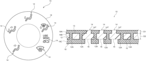
An exemplary embodiment of the present disclosure will be explained in detail below, based on the drawings. It should be noted that for convenience of explanation, as an automobile display device 10 according to the present exemplary embodiment, a display device that is provided at an instrument panel (not illustrated in the drawings) or the like at a vehicle cabin of an automobile and that displays a wind ejection direction and the like of an air conditioning device is used as an example (refer to FIG. 1 ).
As illustrated in FIG. 1 , the automobile display device 10 according to the present exemplary embodiment is formed in a disc shape having a predetermined outer diameter, and a display portion 14 configured with predetermined characters, symbols, and the like is displayed at predetermined intervals in a circumferential direction at a design face thereof. Examples of the display portion 14 include a human shape indicated by a head portion formed in a circular shape and a body portion formed substantially in a crank shape with a predetermined width W1 (for example, about 0.3 mm) (refer to FIG. 2 ), an arrow indicating a direction of wind ejected from an ejection port (not illustrated in the drawings), a window frame and an arrow indicating a defroster, alphabetic characters indicating external air introduction, an automobile shape and an arrow, and the like.
As illustrated in FIG. 2 and FIG. 3 , such an automobile display device 10 is produced by two-color molding of a transmitting member 12 made of a light-transmitting resin, and a non-transmitting member 18 made of a non-light-transmitting resin. The transmitting member 12 serving as a primary molding member that is molded during primary molding of the two-color molding is, for example, white in color, and plural through holes 12A, serving as a bypass flow path configuring circular shapes in a front view, are formed at predetermined portions excluding the display portion 14. The non-transmitting member 18 serving as a secondary molding member that is molded during secondary molding of the two-color molding is, for example, black in color, is filled into the respective through holes 12A of the transmitting member 12, and is provided at a front face 13 side and a rear face 15 side of the transmitting member 12.
Namely, in the non-transmitting member 18, an outer layer 18A provided at the front face 13 side of the transmitting member 12 and an inner layer 18C provided at the rear face 15 side are connected by a connecting portion 18B that is filled into the through holes 12A. Thus, the non-transmitting member 18 is configured such that it is filled into the respective through holes 12A of the transmitting member 12 and is also present at the rear face 15 side thereof, and is formed so as to have a so-called anchor structure with respect to the transmitting member 12.
It should be noted that the non-transmitting member 18 is provided at the front face 13 side and the rear face 15 side of the transmitting member 12 so as to expose an irradiated portion 16 at the rear face 15 side of the transmitting member 12 that is irradiated with light from a light source (not shown in the drawings) and the display portion 14 (more specifically, a leading end portion 14T that will be described later) at the front face 13 side of the transmitting member 12 that emits light due to the light irradiated to the irradiated portion 16 being transmitted.
Further, a thickness D1 of the non-transmitting member 18 provided around the display portion 14 (exposing the leading end portion 14T of the display portion 14) at the front face 13 side of the transmitting member 12 is formed to be thinner than a thickness D2 of the transmitting member 12. Specifically, as illustrated in FIG. 4 , the thickness D1 of the non-transmitting member 18 is equal to or less than three times the width W1 (D1≤3×W1) (also refer to FIG. 2 ) of the leading end portion 14T of the display portion 14 that is exposed from the non-transmitting member 18 (the outer layer 18A), and is less than 1 mm (preferably, about 0.7 mm to 0.8 mm).
Further, a width W2 of a base portion 14D of the display portion 14 at the front face 13 side of the transmitting member 12 is equal to or greater than 1.5 times the width W1 (W2≥1.5×W1) of the leading end portion 14T of the display portion 14. It should be noted that the “base portion 14D” referred to herein is a portion that has a maximum width in a portion continuously formed in a tapered shape (an inclined shape at a predetermined angle) in a thickness direction from the leading end portion 14T of the display portion 14 in the cross-sectional view illustrated in FIG. 4 .
Further, the light-transmitting resin according to the present exemplary embodiment is an amorphous thermoplastic resin, and examples thereof include acrylonitrile butadiene styrene (ABS), polycarbonate (PC), and the like. Furthermore, the non-light-transmitting resin according to the present exemplary embodiment is a crystalline thermoplastic resin having high fluidity, and examples thereof include polybutylene terephthalate (PBT), polypropylene (PP), and the like.
Next, operation of the automobile display device 10 according to the present exemplary embodiment configured as described above will be explained.
The automobile display device 10 is provided at an instrument panel (not illustrated in the drawings) or the like at a vehicle cabin of an automobile, and is configured such that, due to light from the light source being irradiated to the irradiated portion 16 at the rear face 15 side of the transmitting member 12 from the rear face 15 side thereof, one of the display portion 14 configured with the predetermined characters, symbols, or the like is caused to emit light to notify an occupant (not illustrated in the drawings) of a current wind ejection direction or the like of the air conditioning device.
In this regard, in conventional automobile display devices, miniaturization of characters, symbols, and the like has been dealt with by display processing using a painting laser, in which black paint is applied to a white molded member and laser cutting processing is performed. However, in the case of display processing using a painting laser, manufacturing costs are increased due to involving plural processes, and since painting processes are involved, this is not preferable from an environmental standpoint (carbon neutrality).
On the other hand, there are cases in which an automobile display device is produced by two-color molding using a white primary molding member and a black secondary molding member. However, in such cases, when a thickness of the secondary molding member that is provided around a display portion of the primary molding member (to expose the display portion) is set to be thicker, a large amount of a resin material of the secondary molding member is required, and there is a risk that, during secondary molding in which the secondary molding member is molded, deformation (collapse) of the display portion of characters, symbols, or the like in the primary molding member may occur due to fluid pressure of the resin material of the secondary molding member with respect to the primary molding member.
Further, the thicker a thickness of the secondary molding member provided around the display portion of the primary molding member (exposing the display portion) is, the more a proportion of transmitted light that is reflected and absorbed by a wall face along a thickness direction of the secondary molding member provided around the display portion is increased. In other words, the proportion of transmitted light emitted by the display portion decreases, and a luminance of the display portion is reduced.
Accordingly, in order to suppress deformation (collapse) of the display portion and luminance reduction (decrease in the proportion of transmitted light) in the display portion, it is necessary to form the thickness of the secondary molding member provided around the display portion of the primary molding member (exposing the display portion) to be as thin as possible. However, if the thickness of the secondary molding member is formed to be thin, there is a risk that the secondary molding member may peel off from the primary molding member.
Thus, in the automobile display device 10 according to the present exemplary embodiment, in the two-color molding using the transmitting member 12 serving as a primary molding member and the non-transmitting member 18 serving as a secondary molding member, a cross-sectional structure that is sandwiched at the front and rear (a so-called anchor structure) is employed, and as described above, resin materials to be used in the molding are appropriately set, and thicknesses and the like of the molding members are appropriately set. This will be explained below.
When the automobile display device 10 according to the present exemplary embodiment is produced by two-color molding, the plural through holes 12A are formed at predetermined portions, excluding the display portion 14, of the transmitting member 12 in which the display portion 14 such as characters, symbols or the like is formed. The non-transmitting member 18 is then filled into the respective through holes 12A of the transmitting member 12, and is provided in a state in which the display portion 14 and the irradiated portion 16 are exposed at the front face 13 side and the rear face 15 side of the transmitting member 12.
Namely, the non-transmitting member 18 is filled into the respective through holes 12A, is also present at the rear face 15 side of the transmitting member 12, and forms a so-called anchor structure with respect to the transmitting member 12. Accordingly, even if the thickness D1 of the non-transmitting member 18 (the outer layer 18A) provided around the display portion 14 (exposing the leading end portion 14T of the display portion 14) is formed to be thin, peeling off of the non-transmitting member 18 provided around the display portion 14 from the transmitting member 12 can be suppressed.
Consequently, the thickness D1 of the non-transmitting member 18 (the outer layer 18A) can be formed to be as thin as possible. Specifically, the thickness D1 of the non-transmitting member 18 (the outer layer 18A) can be made to be equal to or less than three times the width W1 at the leading end portion 14T of the display portion 14, and can be made to be less than 1 mm (preferably, about 0.7 mm to 0.8 mm).
Accordingly, compared to a case in which the thickness D1 of the non-transmitting member 18 (the outer layer 18A) is greater than three times the width W1 at the leading end portion 14T of the display portion 14 (equal to or greater than 1 mm), occurrence of deformation (collapse) at the display portion 14 of the transmitting member 12 due to the fluid pressure of the non-transmitting member 18 with respect to the transmitting member 12 during secondary molding (during flowing of the non-light-transmitting resin) in which the non-transmitting member 18 is molded can be suppressed or prevented. Thus, even minute characters, symbols, or the like, which could only be processed with a painting laser, can be displayed.
Further, since the thickness D1 of the non-transmitting member 18 (the outer layer 18A) provided around the display portion 14 (exposing the leading end portion 14T of the display portion 14) can be formed to be thin as described above, decreasing of the proportion of transmitted light that is transmitted from the irradiated portion 16 to the display portion 14 (reflection and absorption of the transmitted light at the wall face along the thickness direction of the non-transmitting member 18) can be suppressed, and reduction of the luminance of the display portion 14 can be suppressed.
In particular, the width W2 at the base portion 14D of the display portion 14, which is at the front face 13 side of the transmitting member 12, is made to be equal to or greater than 1.5 times the width W1 at the leading end portion 14T of the display portion 14. Accordingly, luminance reduction in the display portion 14 (in the range from the base portion 14D to the leading end portion 14T) can be even further suppressed, compared to a case in which the width W2 at the base portion 14D of the display portion 14 is made to be smaller than 1.5 times the width W1 at the leading end portion 14T of the display portion 14.
Although the automobile display device 10 according to the present exemplary embodiment has been explained above based on the drawings, the automobile display device 10 according to the present exemplary embodiment is not limited to that which is illustrated in the drawings, and appropriate design modification can be implemented within a range that does not depart from the spirit of the present disclosure. For example, the characters, symbols, and the like that are displayed as the display portion 14 are not limited to those illustrated in the drawings. Further, the automobile display device 10 is also not limited to the disc shape illustrated in the drawings.

Claims (7)

What is claimed is:
1. An automobile display device comprising:
a transmitting member that is made of a light-transmitting resin, that includes, at a rear face side thereof, an irradiated portion to which light from a light source is irradiated, and that includes, at a front face side thereof, a display portion emitting light by transmitting the light that has been irradiated to the irradiated portion, a plurality of through holes being formed at portions of the transmitting member excluding the display portion during primary molding of two-color molding; and
a non-transmitting member that is made of a non-light-transmitting resin, that is partly filled into the through holes during secondary molding of the two-color molding, and that exposes the irradiated portion and the display portion,
wherein the non-transmitting member comprises an outer layer provided at the front face side of the transmitting member, an inner layer provided at the rear face side of the transmitting member, and a connecting portion that is filled into the through holes to connect between the outer layer and the inner layer, the outer layer and the inner layer being wider than the connecting portion.
2. The automobile display device according to claim 1, wherein a thickness of the non-transmitting member provided at the front face side of the transmitting member is equal to or less than three times a width of a leading end portion of the display portion.
3. The automobile display device according to claim 1, wherein a width of a base portion of the display portion is equal to or greater than 1.5 times a width of a leading end portion of the display portion.
4. The automobile display device according to claim 2, wherein a width of a base portion of the display portion is equal to or greater than 1.5 times a width of a leading end portion of the display portion.
5. The automobile display device according to claim 1, wherein
edges of the outer layer and the inner layer of the non-transmitting member in a width direction respectively extend beyond a width of the connecting portion, such that extended edges of the outer layer and the inner layer form an anchoring portion that holds the non-transmitting member to the transmitting member.
6. The automobile display device according to claim 1, wherein
the outer layer of the non-transmitting member is disposed inside an indentation formed on the transmitting member such that a front face side of the outer layer of the non-transmitting member is co-planar with the display portion of the transmitting member.
7. The automobile display device according to claim 5, wherein
the edge of the outer layer in a width direction forms a tapered shape wherein a front face side of the edge of the outer layer is wider than a rear face side of the edge of the outer layer.
US18/433,490 2023-02-28 2024-02-06 Automobile display device Active US12130002B2 (en)

Applications Claiming Priority (2)

Application Number Priority Date Filing Date Title
JP2023030377A JP2024122698A (en) 2023-02-28 2023-02-28 Automotive Display Devices
JP2023-030377 2023-02-28

Publications (2)

Publication Number Publication Date
US20240288145A1 US20240288145A1 (en) 2024-08-29
US12130002B2 true US12130002B2 (en) 2024-10-29

Family

ID=92461420

Family Applications (1)

Application Number Title Priority Date Filing Date
US18/433,490 Active US12130002B2 (en) 2023-02-28 2024-02-06 Automobile display device

Country Status (2)

Country Link
US (1) US12130002B2 (en)
JP (1) JP2024122698A (en)

Citations (5)

* Cited by examiner, † Cited by third party
Publication number Priority date Publication date Assignee Title
JPH0730424U (en) 1993-11-17 1995-06-06 株式会社東海理化電機製作所 Operating knob
JPH08241645A (en) 1995-03-07 1996-09-17 Yazaki Corp Lighting structure of switch knob and method of manufacturing switch knob
JP2007115633A (en) 2005-10-24 2007-05-10 Sunarrow Ltd Key sheet and manufacturing method thereof
US20150294540A1 (en) 2014-04-14 2015-10-15 Yazaki Corporation Indication device
WO2022113457A1 (en) * 2020-11-24 2022-06-02 アルプスアルパイン株式会社 Display device and input device

Family Cites Families (3)

* Cited by examiner, † Cited by third party
Publication number Priority date Publication date Assignee Title
JP4540805B2 (en) * 2000-07-03 2010-09-08 ライオン株式会社 Two-color molded body
WO2012165592A1 (en) * 2011-06-03 2012-12-06 株式会社江東彫刻 Two-color molding die and two-color molding method
JP6004701B2 (en) * 2012-03-30 2016-10-12 三菱重工業株式会社 Display device and vehicle air conditioner equipped with the same

Patent Citations (7)

* Cited by examiner, † Cited by third party
Publication number Priority date Publication date Assignee Title
JPH0730424U (en) 1993-11-17 1995-06-06 株式会社東海理化電機製作所 Operating knob
JPH08241645A (en) 1995-03-07 1996-09-17 Yazaki Corp Lighting structure of switch knob and method of manufacturing switch knob
JP2007115633A (en) 2005-10-24 2007-05-10 Sunarrow Ltd Key sheet and manufacturing method thereof
US20090236209A1 (en) 2005-10-24 2009-09-24 Hisashi Ishii Key sheet and production method thereof
US20150294540A1 (en) 2014-04-14 2015-10-15 Yazaki Corporation Indication device
JP2015204212A (en) 2014-04-14 2015-11-16 矢崎総業株式会社 display device
WO2022113457A1 (en) * 2020-11-24 2022-06-02 アルプスアルパイン株式会社 Display device and input device

Also Published As

Publication number Publication date
US20240288145A1 (en) 2024-08-29
JP2024122698A (en) 2024-09-09

Similar Documents

Publication Publication Date Title
US10246012B2 (en) Steering wheel
US20210221285A1 (en) Steering wheel
US20120033408A1 (en) Design panel and method for producing the same
US20170166117A1 (en) Steering wheel
US20150306801A1 (en) Two-color molding method, two-color molding die and two-color molded article
US20040145884A1 (en) Illuminating mechanism of rotary electric component
US20220299187A1 (en) Lighting Device for a Motor Vehicle, and Method for Producing Such a Lighting Apparatus
US20170334293A1 (en) Vehicular display device
US12130002B2 (en) Automobile display device
US11231158B2 (en) Illumination apparatus for a vehicle with light sources, guide elements and optical separation function
US20080285296A1 (en) Operation panel
JP2001191845A (en) Lighting system for automobile
CN118220307A (en) Steering wheel
JP2003260924A (en) Indicator structure
JP2000301985A (en) Resin window for back window and its manufacture
EP3297869B1 (en) Light guide with improved light cover
CN104210362B (en) Vehicular display apparatus
EP4667286A1 (en) Side turn signal lamp mounting assembly, door body of vehicle, and vehicle
US10239242B2 (en) Method of manufacturing emergency lamp switch
EP4316916B1 (en) Trim for vehicle and glass assembly
JP2025125244A (en) Vehicle emblems
KR20210108618A (en) Structure for a Switch and the Method thereof
JP2009234367A (en) Vehicle display device
JP2021017021A (en) Veneer composite member, lighting device and input device
US12508905B2 (en) Light guide for rotary knob operation device

Legal Events

Date Code Title Description
FEPP Fee payment procedure

Free format text: ENTITY STATUS SET TO UNDISCOUNTED (ORIGINAL EVENT CODE: BIG.); ENTITY STATUS OF PATENT OWNER: LARGE ENTITY

AS Assignment

Owner name: TOYOTA JIDOSHA KABUSHIKI KAISHA, JAPAN

Free format text: ASSIGNMENT OF ASSIGNORS INTEREST;ASSIGNOR:NIWA, TAKASHI;REEL/FRAME:066983/0915

Effective date: 20231103

STPP Information on status: patent application and granting procedure in general

Free format text: NOTICE OF ALLOWANCE MAILED -- APPLICATION RECEIVED IN OFFICE OF PUBLICATIONS

STPP Information on status: patent application and granting procedure in general

Free format text: PUBLICATIONS -- ISSUE FEE PAYMENT VERIFIED

STCF Information on status: patent grant

Free format text: PATENTED CASE