US12125376B2 - Information processing device - Google Patents
Information processing device Download PDFInfo
- Publication number
- US12125376B2 US12125376B2 US16/867,136 US202016867136A US12125376B2 US 12125376 B2 US12125376 B2 US 12125376B2 US 202016867136 A US202016867136 A US 202016867136A US 12125376 B2 US12125376 B2 US 12125376B2
- Authority
- US
- United States
- Prior art keywords
- image
- moving body
- location
- display
- vehicle
- Prior art date
- Legal status (The legal status is an assumption and is not a legal conclusion. Google has not performed a legal analysis and makes no representation as to the accuracy of the status listed.)
- Active, expires
Links
Images


Classifications
-
- G—PHYSICS
- G08—SIGNALLING
- G08G—TRAFFIC CONTROL SYSTEMS
- G08G1/00—Traffic control systems for road vehicles
- G08G1/01—Detecting movement of traffic to be counted or controlled
- G08G1/04—Detecting movement of traffic to be counted or controlled using optical or ultrasonic detectors
-
- G—PHYSICS
- G08—SIGNALLING
- G08G—TRAFFIC CONTROL SYSTEMS
- G08G1/00—Traffic control systems for road vehicles
- G08G1/16—Anti-collision systems
- G08G1/164—Centralised systems, e.g. external to vehicles
-
- G—PHYSICS
- G08—SIGNALLING
- G08G—TRAFFIC CONTROL SYSTEMS
- G08G1/00—Traffic control systems for road vehicles
- G08G1/01—Detecting movement of traffic to be counted or controlled
- G08G1/0104—Measuring and analyzing of parameters relative to traffic conditions
- G08G1/0108—Measuring and analyzing of parameters relative to traffic conditions based on the source of data
- G08G1/0116—Measuring and analyzing of parameters relative to traffic conditions based on the source of data from roadside infrastructure, e.g. beacons
-
- G—PHYSICS
- G06—COMPUTING OR CALCULATING; COUNTING
- G06V—IMAGE OR VIDEO RECOGNITION OR UNDERSTANDING
- G06V20/00—Scenes; Scene-specific elements
- G06V20/10—Terrestrial scenes
-
- G—PHYSICS
- G06—COMPUTING OR CALCULATING; COUNTING
- G06V—IMAGE OR VIDEO RECOGNITION OR UNDERSTANDING
- G06V20/00—Scenes; Scene-specific elements
- G06V20/50—Context or environment of the image
- G06V20/52—Surveillance or monitoring of activities, e.g. for recognising suspicious objects
-
- G—PHYSICS
- G06—COMPUTING OR CALCULATING; COUNTING
- G06V—IMAGE OR VIDEO RECOGNITION OR UNDERSTANDING
- G06V20/00—Scenes; Scene-specific elements
- G06V20/50—Context or environment of the image
- G06V20/52—Surveillance or monitoring of activities, e.g. for recognising suspicious objects
- G06V20/54—Surveillance or monitoring of activities, e.g. for recognising suspicious objects of traffic, e.g. cars on the road, trains or boats
-
- G—PHYSICS
- G08—SIGNALLING
- G08G—TRAFFIC CONTROL SYSTEMS
- G08G1/00—Traffic control systems for road vehicles
- G08G1/01—Detecting movement of traffic to be counted or controlled
- G08G1/0104—Measuring and analyzing of parameters relative to traffic conditions
- G08G1/0125—Traffic data processing
- G08G1/0133—Traffic data processing for classifying traffic situation
-
- G—PHYSICS
- G08—SIGNALLING
- G08G—TRAFFIC CONTROL SYSTEMS
- G08G1/00—Traffic control systems for road vehicles
- G08G1/01—Detecting movement of traffic to be counted or controlled
- G08G1/017—Detecting movement of traffic to be counted or controlled identifying vehicles
-
- G—PHYSICS
- G08—SIGNALLING
- G08G—TRAFFIC CONTROL SYSTEMS
- G08G1/00—Traffic control systems for road vehicles
- G08G1/09—Arrangements for giving variable traffic instructions
- G08G1/0962—Arrangements for giving variable traffic instructions having an indicator mounted inside the vehicle, e.g. giving voice messages
- G08G1/0967—Systems involving transmission of highway information, e.g. weather, speed limits
- G08G1/096766—Systems involving transmission of highway information, e.g. weather, speed limits where the system is characterised by the origin of the information transmission
- G08G1/096783—Systems involving transmission of highway information, e.g. weather, speed limits where the system is characterised by the origin of the information transmission where the origin of the information is a roadside individual element
-
- G—PHYSICS
- G08—SIGNALLING
- G08G—TRAFFIC CONTROL SYSTEMS
- G08G1/00—Traffic control systems for road vehicles
- G08G1/16—Anti-collision systems
- G08G1/165—Anti-collision systems for passive traffic, e.g. including static obstacles, trees
Definitions
- the present disclosure relates to information processing devices which perform visual remote monitoring control for an operator at a remote location to monitor moving bodies, obstacle, etc.
- Patent document 1 Japanese patent laid open publication No. 2019-8474 discloses a monitoring control assist system for assisting an operator to perform the monitoring control of a road and moving bodies on the road so as to detect an abnormality of a moving body, the road and road facilities.
- the monitoring control assist system monitors those moving bodies, pedestrians, etc., and detects occurrence of an abnormality state of a stopped vehicle, a fallen object, a depression or hole in a road.
- the monitoring control assist system highlights the detected abnormality state displayed on a monitor device so as for an operator to correctly monitor the condition of the road with high efficiency.
- an information processing device having a computer system which includes a processor and a storage.
- the processor is configured to provide a first acquisition part, a second acquisition part, an identification part and a display control part.
- the first acquisition part receives and acquires information regarding a first actual location of a moving body on a road transmitted from the moving body.
- the second acquisition part receives and acquires an image acquired by and transmitted from an image acquisition device.
- the storage stores information regarding a correspondence relationship between an image location on the image and a second actual location on the road corresponding to the image location.
- the identification part specifies a moving body image location as a location of the moving body on the image on the basis of the first actual location of the moving body and the information regarding the correspondence relationship.
- the display control part instructs a display device to display the image and information indicating the moving body image location together.
- FIG. 1 is a block diagram showing an information processing device according to a first exemplary embodiment of the present disclosure
- FIG. 2 A is a view showing a schematic image on a X-Y coordinate system to be displayed on a display device shown in FIG. 1 , in which the origin (0, 0) of the X-Y coordinate system is positioned at the upper left corner;
- FIG. 2 B is a view showing each target location corresponding to a coordinate (a longitude, a latitude) on the X-Y coordinate system assigned on the image shown in FIG. 2 A ;
- FIG. 3 is a view showing an example image to be displayed on a display device in the information processing device according to the first exemplary embodiment
- FIG. 4 is a view showing a flow chart explaining behavior of the information processing device according to the first exemplary embodiment
- FIG. 5 A , FIG. 5 B and FIG. 5 C are views showing example images to be displayed on the display device controlled by the information processing device according to the first exemplary embodiment
- FIG. 6 is a view showing another example image to be displayed on the display device controlled by the information processing device according to the first exemplary embodiment
- FIG. 7 A and FIG. 7 B are views showing example images to be displayed on the display device controlled by the information processing device according to a second exemplary embodiment of the present disclosure
- FIG. 8 is a view showing an example image displayed on the display device under the control of the information processing device according to a third exemplary embodiment of the present disclosure.
- FIG. 9 is a view showing an example image displayed on the display device under the control of the information processing device according to a fourth exemplary embodiment of the present disclosure.
- FIG. 10 is a block diagram showing the information processing device according to a fifth exemplary embodiment of the present disclosure.
- FIG. 11 is a view showing an image displayed on the display device under the control of the information processing device according to the fifth exemplary embodiment.
- FIG. 12 is a view showing the vehicle running on a traffic lane and a plurality of cameras as the image acquisition devices installed along the traffic lane.
- FIG. 1 is a block diagram showing the information processing device 100 according to the first exemplary embodiment.
- the information processing device 100 communicates with various types of devices, for example with moving bodies such as vehicles 10 , one or more image acquisition devices such as cameras 20 , and with a display device 30 through a wired communication network and a wireless communication network.
- the information processing device 100 communicates with the vehicle 10 and the camera 20 through the wireless communication network.
- the information processing device 100 communicates with the display device 30 through the wired communication network.
- the information processing device 100 and the display device 30 are installed at a traffic operations center, for example.
- the operator monitors the vehicle 10 as a remote monitoring target object on the image displayed on the display device 30 installed at the traffic operations center.
- the description will now be given of the information processing device 100 which performs a remote monitoring control so as to assist the remote monitoring operation of the vehicle 10 .
- the information processing device 100 it is possible for the information processing device 100 to monitor moving bodies such as pedestrians, etc. in addition to vehicles.
- the moving bodies represent various objects capable of moving at any moving speed.
- the moving bodies further represent stopped bodies on a road.
- the moving bodies may also represent motor vehicles, trucks, motor cycles, bicycles, pedestrians, ships, boats, aircrafts, loaded cargos and containers therein, etc.
- the vehicle 10 is equipped with a Global Positioning System (GPS).
- GPS Global Positioning System
- the vehicle 10 detects an own location detected by the GPS and transmits the information regarding the detected own location to the information processing device 100 through the wireless communication network.
- the vehicle 10 represents an autonomous vehicle (AV) or an manually-operated vehicle.
- the camera 20 as an image acquisition device is a monitoring camera installed at an urban area and a shoulder of a road.
- the camera 20 transmits acquired image to the information processing device 100 through the wireless communication network.
- the information processing device 100 receives original image data transmitted form the camera 10 , and processes the received image data as needed, and transmits the original image data and the processed image data to the display device 30 .
- the display device 30 receives those image data transmitted from the information processing device 100 , and displays the received image data on a screen thereof.
- the information processing device 100 is realized by using a computer system such as one or more central processing units and a storage 103 as a memory.
- the processor in the computer system provides a vehicle information acquisition part 101 , an image data acquisition part 102 , an identification part 104 and a display control part 105 .
- the vehicle information acquisition part 101 (which corresponds to a first acquisition part) receives information of a moving location of the vehicle 10 (which corresponds to a first actual location of the vehicle 10 ) transmitted from the vehicle 10 .
- the moving location of the vehicle 10 is specified by using a longitude and latitude of the actual location of the vehicle 10 .
- the image data acquisition part 102 (which corresponds to a second acquisition part) sequentially receives image data, acquired in real time by, transmitted from the camera 20 .
- the image data acquisition part 102 corresponds to a second acquisition part.
- the storage 103 is composed of non-volatile memory devices such as a hard disk drive, a flash memory, etc.
- the storage 103 stores a correspondence relationship between an image location on the image and an actual location on a road (as a second actual location) corresponding to the image location.
- the image location on the image has been acquired by the camera 20 and to be displayed on the display device 30 .
- the actual location on the road corresponding to the image location on the image is used as a target location, and the location on the image is referred to as an image location, in short.
- the target location can be represented by longitude and latitude.
- the correspondence relationship between the target location and the image location stored in the storage 103 will be explained later.
- the location on the image includes a location of a remote monitoring target body on an image and a location of a remote monitoring target which is hidden by a building on the image.
- the identification part 104 estimates, i.e. specifies, a vehicle image location of the vehicle 10 on the image, as an estimated vehicle image location which corresponds to a moving body image location by using the moving location of the vehicle 10 acquired by the vehicle information acquisition part 101 on the basis of the correspondence relationship between the target location and the image location stored in the storage 103 .
- the estimated vehicle image location is used as the moving body image location.
- the identification part 104 determines the location on the image which corresponds to the moving location of the vehicle 10 on the basis of the correspondence relationship between the target location and the image location. It is possible to estimate that the vehicle 10 is displayed at a location on the image corresponding to the moving location of the vehicle 10 . For this reason, the identification part 104 identifies that the location on the image corresponding to the moving location of the vehicle 10 indicates the vehicle image location, i.e. the estimated vehicle image location.
- the display control part 105 instructs, i.e. transmits the image acquired by the image data acquisition part 102 to the display device 30 so as to display the image on a screen of the display device 30 .
- the display control part 105 further instructs the display device 30 to display both the information regarding the vehicle image location and the image acquired by the image data acquisition part 102 together on the screen of the display device 30 .
- the display control part 105 may simply transmit both the image and the information regarding the vehicle image location to the display device 30 .
- the information processing device 100 it is sufficient for the information processing device 100 to generate the information showing the vehicle image location so long as the operator can easily recognize and identify the presence of the target vehicle as a remote monitoring target.
- the information processing device 100 it is possible for the information processing device 100 to use various types of markers having a different size such as lines, arrows, circles, squares, etc. to be displayed on the image so as to indicate the vehicle image location.
- the information processing device 100 it is sufficient for the information processing device 100 to generate the information showing a position on the image based on the vehicle image location. For example, it is sufficient for the information processing device 100 to use those markers such as lines, arrows, circles, squares, etc. as previously described which is shifted by a predetermined distance from the vehicle image location identified by the identification part 104 . This prevents the remote monitoring target vehicle and the marker from being displayed together on the image displayed on the display device 30 . That is, this allows for the operator to correctly recognize the remote monitoring target vehicle and the marker which are displayed at a different position from each other on the image displayed on the display device 30 .
- those markers such as lines, arrows, circles, squares, etc.
- the target location represents the actual location on the road corresponding to the location on the image acquired by the camera 20 .
- the image location represents the location on the image displayed on the display device 30 .
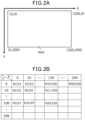
- FIG. 2 A is a view showing a schematic image in a X-Y coordinate system to be displayed on the display device 30 , in which the origin (0, 0) of the X-Y coordinate system is positioned at the upper left corner.
- the maximum X coordinate has 250
- the maximum Y coordinate is 200 in the X-Y coordinate system shown in FIG. 2 A .
- the minimum unit in the X-Y coordinate system shown in FIG. 2 A is one pixel, for example.
- FIG. 2 B is a view showing each target location corresponding to a coordinate (a longitude, a latitude) on the X-Y coordinate system assigned on the image shown in FIG. 2 A .
- the origin (0, 0) in the X-Y coordinate system on the image displayed on the display device 30 corresponds to the actual location represented by using the longitude and latitude (N1, E1).
- the coordinate (250, 0) in the X-Y coordinate system corresponds to the actual location (N50, E50).
- FIG. 2 B shows only a part of the target locations for brevity.
- Each of the overall coordinates in the X-Y coordinate system has a respective target location in the correspondence relationship stored in the storage 103 .
- the information processing device 100 it is sufficient for the information processing device 100 according to the first exemplary embodiment to use any correspondence relationship between the target location of a moving body acquired by the camera 20 and the image location on the image thereof. Accordingly, it is possible for the information processing device 100 to use any method so long as it correctly obtains the target location.
- the vehicle information acquisition part 101 acquires the moving location (N30, E30) of the vehicle 10
- the identification part 104 it is possible for the identification part 104 to specify the image location (120, 100) as the vehicle image location.
- FIG. 3 is a view showing an example image to be displayed on the display device 30 in the information processing device 100 according to the first exemplary embodiment.
- the identification part 104 determines the target location nearest the moving location of the vehicle 10 , and to specify the image location corresponding to the determined target location nearest the moving location of the vehicle 10 .
- the identification part 104 select and determine, as the vehicle image location, the image location (0, 10) corresponding to the target location (N2, E2) nearest the moving location of the vehicle 10 .
- the identification part 104 it is acceptable for the identification part 104 to perform linear interpolation so as to specify the image location, which does not correspond to the target location, from a plurality of target locations close to the moving location of the vehicle 10 .
- the identification part 104 specifies (0, 5) as a median of the image location (0, 0) corresponding to the target location (N1, E1) and the image location (0, 10) corresponding to the target location (N2, E2).
- the storage 103 Before performing a series of processing shown in FIG. 4 , the storage 103 has stored the information regarding the correspondence relationship between the target location and the image location, which has been previously explained at (2).
- FIG. 4 is a view showing a flow chart explaining the behavior of the information processing device 100 according to the first exemplary embodiment.
- step S 101 shown in FIG. 4 the vehicle information acquisition part 101 in the information processing device 100 receives the moving location of the vehicle 10 as the actual location of the vehicle 10 on a road transmitted from the vehicle 10 .
- the operation flow progresses to step S 102 .
- step S 102 the image data acquisition part 102 receives the image acquired by the camera 20 .
- the operation flow progresses to step S 103 .
- step S 103 the identification part 104 specifies the vehicle image location as the location of the vehicle 10 on the image which corresponds to the moving location of the vehicle 10 acquired at S 101 on the basis of the correspondence relationship between the target location and the image location which has been stored in the storage 103 .
- the operation flow progresses to step S 104 .
- step S 104 the display control part 105 instructs the display device 30 to display the information regarding the vehicle image location on the image acquired at S 102 .
- the vehicle information acquisition part 101 continuously receives the information regarding the moving location of the vehicle 10 transmitted at predetermined intervals from the vehicle 10 .
- the information processing device 100 repeatedly performs the series of processing shown in FIG. 4 every when receiving the latest moving location of the vehicle 10 . This makes it possible to update the information representing the vehicle image location displayed on the display device 30 .
- the information processing device 100 according to the first exemplary embodiment, i.e. specifically the display control part 105 , instructs the display device 30 to display the vehicle image location with high accuracy even if the location of the vehicle 10 on the image, i.e. the vehicle image location on the image is moving associated with the moving of the vehicle 10 on a road.
- FIG. 5 A , FIG. 5 B and FIG. 5 C are views showing example images to be displayed on the display device 30 instructed and controlled by the information processing device 100 according to the first exemplary embodiment.
- FIG. 5 A shows an example image with a line mark (e.g. a black-color line mark) at the center thereof displayed on the display device 30 as the information representing the vehicle image location.
- the line mark shown in FIG. 5 A passes through the vehicle image location. It is acceptable for the information processing device 100 to use various types and color of line marks.
- FIG. 5 B shows an example image with an arrow mark (e.g. a black-color arrow mark) which represents the vehicle image location.
- FIG. 5 C shows an example image with a circle mark around the vehicle image location.
- FIG. 6 is a view showing another example image to be displayed on the display device 30 controlled by the information processing device 100 according to the first exemplary embodiment.
- the vehicle as the remote monitoring target body and a part of the road are hidden by the two buildings located between the vehicle 10 (not shown) and the camera 20 (not shown).
- the identification part 104 estimates the vehicle image location on the image on the basis of the moving location of the vehicle 10 transmitted from the vehicle 10 , it is possible to correctly specify the vehicle image location of the vehicle 10 on the image even if the vehicle 10 is hidden by the building and it is difficult to display the location of the vehicle 10 on the display device 30 .
- the information processing device 100 does not use and perform any image analysis process.
- the concept of the present invention is not limited by the disclosure of the first exemplary embodiment. It is possible for the information processing device 100 to be equipped with an image analysis part (not shown) performing an image analysis processing so as to assist the operator's monitoring operation of the remote monitoring target vehicle.
- the information processing device 100 determines the target vehicle, the location of which is closest to the specified vehicle image location, to be monitored on the image displayed on the display device 30 .
- the display control part 105 instructs the display device 30 to display the information regarding the target vehicle and to trace a driving locus of the remote monitoring target vehicle by using an image analysis method.
- the display control part 105 detect a road width by using the image analysis technology, and to instruct the display device 30 to display the line mark having the same length of the detected road width on the image.
- the information processing device 100 can correctly specify the location of the remote monitoring target vehicle on the image on the basis of the correspondence relationship between the target location and the image location, where the target location represents the actual location on the road corresponding to the location on the image, and the image location represents the location on the image).
- FIG. 7 A and FIG. 7 B are views showing example images to be displayed on the display device 30 controlled by the information processing device 100 according to the second exemplary embodiment.
- the first exemplary embodiment has explained the structure of the information processing device 100 which specifies, as the vehicle image location, the location on the image corresponding to the moving location of the vehicle 10 .
- the second exemplary embodiment will disclose a method which is referred to a computer implemented method, to be performed by the image processing device 100 which specifies the location of the remote monitoring target vehicle 10 on the image with high accuracy while compared with the method performed by the first exemplary embodiment.
- the vehicle information acquisition part 101 receives information regarding a moving time and a moving speed of the vehicle 10 , where the moving time represents the time when the GPS mounted on the vehicle 10 receives the moving location of the vehicle 10 itself, and the moving speed of the vehicle 10 is detected by a speed sensor mounted on the vehicle 10 .
- the time when the GPS mounted on the vehicle 10 acquires the moving location of the vehicle 10 corresponds to a first time.
- the image data acquisition part 102 receives information regarding a capturing time (which corresponds to a second time) when the camera 20 acquires the image in addition to the information regarding the image transmitted from the camera 20 .
- the information processing device 100 receives the first time and the second time synchronized from each other through a network time protocol (NTP).
- NTP network time protocol
- the vehicle information acquisition part 101 and the image data acquisition part 102 receive various information regarding the moving location of the vehicle 10 and the image acquired by the camera 20 through a wireless communication network. For this reason, a time delay may occur due to a congestion in the NTP. That is, a possible time delay will occur, where a receiving time when the vehicle information acquisition part 101 receives the information regarding the first time is delayed from the first time when the GPS mounted on the vehicle 10 acquires the moving location of the vehicle 10 , or a receiving time when the image data acquisition part 102 receives the information regarding the second time is delayed from the second time when the camera 20 acquires the image.
- this time delay causes a timing difference between the first time when the GPS mounted on the vehicle 10 acquires the moving location of the vehicle 10 and the second time when the camera 20 acquires the image.
- This time delay will cause a possible error in which the location of the vehicle 10 on the image is shifted from the correct location of the vehicle 10 on the image.
- the information processing device 100 adjusts and corrects the timing difference between the first time and the second time, where the first time represents the time when the GPS mounted on the vehicle 10 acquires the moving location of the vehicle 10 and the second time represents the time when the camera 20 acquires the image.
- the identification part 104 specifies the image location, as the moving body image location, which corresponds to the moving location of the vehicle 10 acquired by the vehicle information acquisition part 101 based on the correspondence relationship between the target location and the image location. This correspondence relationship between the target location and the image location has been previously explained in the first exemplary embodiment.
- the information processing device 100 specifies the moving body image location as the image location, which will be used as the moving body image location before correction.
- the second exemplary embodiment corrects this moving body image location before correction so as to obtain the moving body image location after correction with high accuracy.
- the identification part 104 calculates a movement distance of the vehicle 10 during the time period measured from the moving time as first time when the GPS mounted on the vehicle 10 acquires the moving location of the vehicle 10 to the capturing time as the second time when the camera 20 acquires the image on the basis of a time difference between the first time and the second time, and the moving speed of the vehicle 10 obtained by the vehicle information acquisition part 101 .
- the identification part 104 converts the calculated movement distance of the vehicle 10 to an image distance on the image. It is acceptable for the identification part 104 to use another computer implemented method capable of converting the calculated movement distance to the image distance displayed on the image.
- the storage 103 it is acceptable for the storage 103 to store in advance information representing a correspondence relationship between the image distance between X and Y coordinates on the image and an actual distance between the target locations corresponding to these X and Y coordinates.
- the identification part 104 specifies a moving direction of the vehicle 10 to which the vehicle 10 has moved during the time period measured from the moving time as the first time when the GPS mounted on the vehicle 10 has acquired the moving location of the vehicle 10 to the second time when the camera 20 has acquired the image. For example, it is possible for the identification part 104 to specify the moving direction of the vehicle 10 on the basis of the information regarding the moving direction of the vehicle 10 transmitted from the vehicle 10 and acquired by the vehicle information acquisition part 101 .
- the example previously described has been processed on an assumption that the first time when the GPS mounted on the vehicle 10 acquires the moving location of the vehicle 10 is delayed from the second time when the camera 20 acquires the image.
- the second time when the camera 20 acquires the image may be delayed from the first time when the GPS mounted on the vehicle 10 acquires the moving location of the vehicle 10 .
- the identification part 104 further specifies the vehicle image location to which the vehicle 10 has moved on the image in the moving direction of the vehicle 10 from the moving body image location before correction, corresponding to the calculated actual moving direction of the vehicle 10 on the road.
- the identification part 104 determines this specified moving body image location as the vehicle image location of the vehicle 10 on the image.
- the identification part 104 it is possible for the identification part 104 to use a predetermined direction instead of using the information regarding the moving direction of the vehicle 10 transmitted from the vehicle 10 and acquired by the vehicle information acquisition part 101 .
- the identification part 104 specifies a moving body image location shifted in a predetermined moving direction on the road on the basis of the moving body image location before correction. It is possible for the identification part 104 to perform the image processing analysis to recognize this predetermined moving direction. It is sufficient to use, as the predetermined moving direction, a possible direction toward which the vehicle can move within a predetermined distance. For example, it is sufficient to use the predetermined moving direction of the vehicle which indicates the forward direction of the vehicle on the road. Further, it is acceptable to use, as the predetermined moving direction, a forward direction or a backward direction on the road.
- the information processing device 100 may have a structure in which the display control part 105 instructs the display device 30 to display, in addition to information regarding the estimated vehicle image location, information regarding the moving body image location before correction which has been obtained when the vehicle image location is specified. That is, the estimated vehicle image location may be shifted from the location of the vehicle on the image due to a rapid change of a moving speed of the vehicle after the location of the vehicle 10 on the image has been corrected by using the method, i.e. the computer implemented method previously described.
- the operator it is possible for the operator to correctly recognize the possible occurrence previously described by displaying the vehicle image location as the moving body image location and the moving body image location before correction on the image simultaneously. For example, it is sufficient to simply display the estimated vehicle image location and the location of the vehicle on the image displayed on the display device 30 so long as the operator clearly and correctly recognizes them on the image. For example, it is acceptable to use a single marker representing them at the same location on the image so long as the operator clearly and correctly recognizes them on the image.
- FIG. 7 A and FIG. 7 B show two display examples of the image displayed on the display device 30 .
- FIG. 7 A shows a display example to use two markers which represent the vehicle image location (as the moving body image location) before correction and after correction.
- FIG. 7 B shows another display example to use a single marker with a color graduation by which the vehicle image location before correction is clearly different in color from the vehicle image location after correction.
- the display device 30 displays the information regarding the vehicle image location (as the moving body image location) before correction in the examples shown in FIG. 7 A and FIG. 7 B , it is difficult for the operator to correctly recognize whether the remote monitoring target is the vehicle 10 or another vehicle behind.
- the information processing device 100 corrects the location of the vehicle 10 on the image and displays the corrected location on the image. This makes it possible for the operator to correctly recognize the vehicle 10 on the image.
- the information processing device 100 instructs the display device 30 to display the marker representing the position at which the vehicle 10 is present before and after the correction. This makes it possible for the operator to correctly recognize the vehicle 10 on the image because the display device 30 displays the possible range on the image in which the vehicle 10 is present even if the estimated vehicle image location is shifted from the location of the vehicle 10 on the image.
- the information processing device 100 specifies the location of the vehicle 10 on the image with high accuracy, and this makes it possible for the operator to monitor the remote monitoring target object without error.
- the modification uses another method of correcting the vehicle image location (i.e. the moving body image location) which is the remote monitoring target on the image, i.e. corrects the location of the vehicle 10 on the image.
- the vehicle information acquisition part 101 and the image data acquisition part 102 according to the modification obtains the information regarding the moving time (as the first time) and the moving speed of the vehicle 10 , and the capturing time as the second time.
- the identification part 104 calculates the movement distance of the vehicle 10 during the time period measured from the moving time as first time when the GPS mounted on the vehicle 10 acquires the moving location of the vehicle 10 to the capturing time as the second time when the camera 20 acquires the image on the basis of the time difference between the first time and the second time.
- the identification part 104 calculates the location of the vehicle 10 measured from the moving location of the vehicle 10 obtained by the vehicle information acquisition part 101 on the basis of the calculated movement distance in the moving direction of the vehicle 10 .
- This calculated location of the vehicle 10 corresponds to the actual location of the vehicle 10 on the road (as a third actual location) at the capturing time of the camera 20 .
- the identification part 104 specifies the vehicle image location (as the moving body image location), i.e. the location of the vehicle 10 on the image which corresponds to the actual location of the vehicle 10 on the road at the capturing time of the camera 20 on the basis of the correspondence relationship between the target location and the image location stored in the storage 103 .
- the identification part 104 determines this specified vehicle image location as the vehicle image location of the vehicle 10 on the image.
- the identification part 104 does not specify the vehicle image location before correction. Accordingly, the display control part 105 instructs the display device 30 to display the information regarding the vehicle image location of the vehicle 10 as the vehicle image location after correction only.
- the first and second exemplary embodiments previously described may have a case in which the display device 30 displays an image having an area where no vehicle may be moving. It is not necessary for the display device 30 to display the image having such area. This often causes a possible incorrect monitoring where the operator may lose a remote monitoring target body due to the presence of such area.
- the third exemplary embodiment provides the information processing device 100 having a structure capable of adjusting a degree of resolution and/or brilliant of an image or a part of the image.
- the display control part 105 adjusts the resolution and/or brightness of a specific area in the image to be displayed on the display device 30 . That is, the display control part 105 instructs the display device 30 to display the image including the specific area with the adjusted resolution and brightness.
- an image acquired by the camera 20 as the image acquisition device includes a first area and a second area.
- the first area includes roads on which vehicles are moving.
- the second area includes rivers, mountains, sky, buildings where unlikely that vehicles will be driving.
- the display control part 105 adjusts the image acquired by the camera 20 so that the first area in the image has the resolution and brightness which are higher than the resolution and brightness of the second area. For example, the display control part 105 determines the area corresponding to the second area on the image, and reduces the resolution and brightness of the determined area as the second area. It is acceptable for the display control part 105 to determine the area corresponding to the first area on the image, and increases the resolution and brightness of the determined area as the first area.
- the information processing device 100 select any method of adjusting the resolution and brightness of the determined area on the acquired image to be displayed on the display device 30 .
- the identification part 104 determines the area on the basis of the correspondence relationship between the target location and the image location stored in the storage 103 , and to adjust the brightness of the determined area.
- the correspondence relationship has been explained in the first exemplary embodiment.
- the information processing device 100 receives position information such as a longitude and a latitude thereof, where it is difficult for a vehicle to drive, transmitted from a map database (not shown).
- the identification part 104 specifies the location regarding the received position information on the image on the basis of the correspondence relationship between the target location and the image location.
- the identification part 104 determines the specified area on the image and reduces the resolution and brightness of the area including the specified location.
- the information processing device 100 prefferably performs the image analysis function so as to automatically determine an area, where vehicles are unlikely to be present, on the acquired image, and to reduce the resolution or brightness of the determined area on the image. It is acceptable for the operator to manually select and determine this area on the image.
- FIG. 8 is a view showing an example image displayed on the display device 30 under the control of the information processing device 100 according to the third exemplary embodiment.
- FIG. 8 shows the example image displayed on the display device 30 , on which the area except for the road area has a reduced resolution which is lower than the resolution of the road area on the image.
- this makes it possible to increase the efficiency of performing the visual remote monitoring control of moving bodies such as the vehicle 10 at a remote location.
- the display control part 105 instructs the display device 30 to display predicted image positions, through which the vehicle 10 will be passing, and finally reach the final destination on the image.
- Autonomous vehicles or self-driving vehicles determine in advance a final destination to which a vehicle will reach, and a plurality of predicted transit positions through which the vehicle will be passing.
- the autonomous vehicle adjusts the behavior of the vehicle so as to pass through the predicted transit positions in order. This control allows the vehicle to correctly pass the predicted transit positions and to reach the final destination. That is, autonomous vehicles have in advance position information regarding predicted transit positions which the vehicle will be passing through, and to reach the final destination.
- the identification part 104 specifies image positions corresponding to the predicted transit positions acquired by the vehicle information acquisition part 101 on the basis of the correspondence relationship between the target location and the image location stored in the storage 103 .
- the specified image positions correspond to the respective predicted image positions on the image through which the vehicle 30 will be passing on the image displayed on the display device 30 .
- the display control part 105 instructs the display device 30 to display the image acquired by the image data acquisition part 102 and the predicted image positions together. It is further acceptable for the display control part 105 to connect the predicted image positions from each other so as to show predicted image paths of the vehicle 10 on the image.
- FIG. 9 is a view showing an example image displayed on the display device 30 under the control of the information processing device 100 according the fourth exemplary embodiment.
- circle marks represent the predicted image positions on the image
- dotted lines represent predicted image paths which connect the predicted image positions, in addition to the location of the vehicle 10 on the image. It is possible for the operator to easily perform visual recognition of the predicted image paths on the image through which the vehicle 10 will drive.
- FIG. 9 shows an obstacle in front of the vehicle 10 on the traffic lane in the image.
- the vehicle 10 When the vehicle 10 moves forward on the traffic lane, the vehicle 10 will collide with the obstacle. In order to avoid this, the operator can perform the drive assist for the vehicle 10 on the basis of the image shown in FIG. 9 .
- the information processing device 100 allows the operator to monitor various types of moving bodies, for example, to monitor the vehicle 10 as a remote monitoring target while considering the predicted drive path on the image, and further allows the operator to perform the correct drive assist control of the vehicle 10 .
- the information processing device 100 performs the remote monitoring control so as to assist the remote monitoring operation of the vehicle 10 .
- the operator in a traffic operations center monitors the vehicle 10 as the remote monitoring target on the image displayed on the display device 30 .
- the operator in the traffic operations center monitors simultaneously a plurality of images acquired by the plurality of cameras 20 as the image acquisition devices installed at a plurality of locations, and obtain a plurality of drive paths of a plurality of vehicles on the images.
- the information processing device 110 provides a remote monitoring control of a specific vehicle on the basis of the images transmitted from the plurality of cameras 20 and information regarding driving locations of vehicles transmitted from the plurality of vehicles.
- FIG. 10 is a block diagram showing the information processing device 110 according to the fifth exemplary embodiment of the present disclosure. As shown in FIG. 10 , the information processing device 110 according to the fifth exemplary embodiment has a target selection part 111 in addition to the components in the information processing device 110 according to the first to fourth exemplary embodiments.
- FIG. 11 is a view showing an image displayed on the display device 30 under the control of the information processing device 110 according to the fifth exemplary embodiment.
- the display device 30 has a first display device 31 and a second display device 32 .
- the first display device 31 displays each of images acquired by and transmitted from the plurality of cameras 20 .
- the second display device 32 displays an enlarged image of the image selected from the plurality of images displayed on the first display device 31 .
- the second display device 32 displays information regarding identification numbers or characters of the vehicles which are transmitting the driving location of the vehicles to the information processing device 110 .
- the target selection part 111 selects, as a remote monitoring target object, the vehicle 10 selected by the operator from the plurality of vehicles acquired by the vehicle information acquisition part 101 .
- the target selection part 111 selects, as the monitoring target object, the vehicle having the specific identification number, selected by the operator through an input device (not shown) in the traffic operations center, from the vehicles displayed on the second display device 32 .
- FIG. 11 shows the image in which the target selection part 111 selects the vehicle having the identification number ID003.
- the target selection part 111 selects the vehicle as the monitoring target object which has been selected by the operator in the operator in the traffic operations center.
- the concept of the present disclosure is not limited by this.
- the identification part 104 selects and specifies the image including, i.e. displaying the vehicle 10 selected by the target selection part 111 from the plurality of images displayed on the first display device 31 . Specifically, the identification part 104 specifies the vehicle image location of the vehicle 10 on the image on the basis of the correspondence relationship between the target location and the image location which has been stored in the storage 103 .
- the identification part 104 specifies the image including the specified vehicle image location of the vehicle 10 from the plurality of images displayed on the first display device 31 . It is preferable for the identification part 104 to instruct the display control part 105 to highlight the frame of the specified image.
- the identification part 104 selects the image location which corresponds to the driving location (N30, E30) on the basis of the correspondence relationship between the target location and the image location which has been stored in the storage 103
- the identification part 104 specifies the specific image including the image location (see the image designated by bold frames at the lower left side shown in FIG. 11 ) in the plurality of images displayed on the first display device 31 .
- the display control part 105 instructs the second display device 32 to enlarge the image specified by the identification part 104 , and to display the enlarged image.
- the information processing device 110 has the structure which makes it possible to specify and display the specific image including the monitoring target object when the display device displays a plurality of images acquired by and transmitted from a plurality of image acquisition devices.
- the identification part 104 selects, from the plurality of images displayed on the first display device 31 , an image having a high possibility in which the vehicle 10 will be shown in the near future, instead of selecting the image in which the vehicle 10 is shown.
- the vehicle information acquisition part 101 acquires a predicted transit position to which the vehicle will move in the near future in addition to the driving location of the vehicle 10 , similar to the function of the information processing device according to the fourth exemplary embodiment.
- the identification part 104 specifies a predicted image location corresponding to the predicted transit position of the vehicle 10 on the basis of the correspondence relationship between the target location and the image location stored in the storage 103 .
- the identification part 104 specifies the image including the predicted image location from the images displayed on the first display device 31 .
- the identification part 104 When the vehicle information acquisition part 101 has received the moving speed of the vehicle 10 , it is possible for the identification part 104 to calculate a time period until the vehicle will reach the predicted transit position on the basis of the received moving speed of the vehicle 10 . In this case, the identification part 104 extracts the predicted transit position only through which the vehicle 10 will pass within a predetermined time period (for example, five minutes), and selects, i.e. specifies the image including the predicted transit position extracted by the identification part 104 .
- a predetermined time period for example, five minutes
- the identification part 104 specifies the predicted image position on the basis of the correspondence relationship between the target location and the image location stored in the storage 103 , and specifies the image including the predicted image positions.
- the identification part 104 it is acceptable for the identification part 104 to specify the image having a high possibility, in which the vehicle will be shown in the near future, on the basis of the driving location and direction of the vehicle 10 .
- FIG. 12 is a view showing the vehicle 10 running on a traffic lane and cameras 20 - 1 and 20 - 2 as the image acquisition devices installed along the traffic lane.
- the images acquired by the cameras 20 - 1 and 20 - 2 do not include any vehicle 10 .
- the identification part 104 specifies the camera 20 - 1 when the information processing device has a structure in which the identification part 104 specifies the camera closest to the driving location of the vehicle 10 .
- the structure of the modification makes it possible to specify the image which will show the vehicle 10 in the near future, and to instruct the second display device 32 to display the image corresponding to the predicted image position in the near future. This structure of the modification allows the operator to correctly monitor the vehicle 10 as the remote monitoring target object as soon as the vehicle enters the monitoring area of the camera 20 - 2 .
- FIG. 1 and FIG. 10 represent the functions as the structure of the information processing device according to the present disclosure. It is possible to realize those functions by using a combination of hardware and software programs. It is possible to use a method capable of realizing these functions of the present disclosure.
- the software program can cause a central processing unit (CPU, or a processor) to execute these functions of the present disclosure.
- a computer system is composed of a CPU, a memory and a hard disk drive as a non-transitory computer readable storage medium.
- a non-transitory tangible storage medium for example, a non-transitory tangible storage medium, a dedicated or a general purpose hardware such as a hard disk drive, a universal serial bus memory (USB memory), a compact disk (CD), a blue-ray disk (BD), an internal memory device such as a RAM, ROM, etc. It is possible to receive these software programs stored in the memory devices through a communication network, and to store the received software programs into a dedicated memory. This allows easy upgrading of the software programs, and for the information processing unit to receive the latest upgraded software programs.
- the information processing device according to the present disclosure performs a real-time remote monitoring control by the operator.
- the concept of the present disclosure is not limited by this. It is possible to apply the information processing device according to the present disclosure to an application for recognize a past movement of a moving body on the basis of past locations of the moving body and past images acquired by the cameras.
Landscapes
- Physics & Mathematics (AREA)
- General Physics & Mathematics (AREA)
- Engineering & Computer Science (AREA)
- Multimedia (AREA)
- Theoretical Computer Science (AREA)
- Chemical & Material Sciences (AREA)
- Analytical Chemistry (AREA)
- Life Sciences & Earth Sciences (AREA)
- Atmospheric Sciences (AREA)
- Traffic Control Systems (AREA)
- Closed-Circuit Television Systems (AREA)
Abstract
Description
Claims (9)
Applications Claiming Priority (2)
| Application Number | Priority Date | Filing Date | Title |
|---|---|---|---|
| JP2019-087810 | 2019-05-07 | ||
| JP2019087810A JP7140043B2 (en) | 2019-05-07 | 2019-05-07 | Information processing equipment |
Publications (2)
| Publication Number | Publication Date |
|---|---|
| US20200357272A1 US20200357272A1 (en) | 2020-11-12 |
| US12125376B2 true US12125376B2 (en) | 2024-10-22 |
Family
ID=73045170
Family Applications (1)
| Application Number | Title | Priority Date | Filing Date |
|---|---|---|---|
| US16/867,136 Active 2042-07-16 US12125376B2 (en) | 2019-05-07 | 2020-05-05 | Information processing device |
Country Status (3)
| Country | Link |
|---|---|
| US (1) | US12125376B2 (en) |
| JP (1) | JP7140043B2 (en) |
| CN (1) | CN111915900B (en) |
Families Citing this family (3)
| Publication number | Priority date | Publication date | Assignee | Title |
|---|---|---|---|---|
| DE102021204067A1 (en) * | 2021-04-23 | 2022-10-27 | Continental Automotive Technologies GmbH | Method of creating a collision probabilities map |
| WO2023010236A1 (en) * | 2021-07-31 | 2023-02-09 | 华为技术有限公司 | Display method, device and system |
| US20240346967A1 (en) * | 2023-04-13 | 2024-10-17 | Esper.io, Inc. | Automated Device-Interaction Emulator for Provisioning and Testing |
Citations (21)
| Publication number | Priority date | Publication date | Assignee | Title |
|---|---|---|---|---|
| JP2002117494A (en) | 2000-10-11 | 2002-04-19 | Honda Motor Co Ltd | Peripheral information display device |
| JP2004104274A (en) | 2002-09-06 | 2004-04-02 | Hitachi Ltd | Monitoring system |
| JP2005045618A (en) | 2003-07-23 | 2005-02-17 | Sony Corp | Monitoring device |
| JP2008046744A (en) | 2006-08-11 | 2008-02-28 | Sumitomo Electric Ind Ltd | Approaching moving body display device, system and method |
| JP2008059178A (en) | 2006-08-30 | 2008-03-13 | Nippon Soken Inc | Operation support device and program |
| US20090262195A1 (en) | 2005-06-07 | 2009-10-22 | Atsushi Yoshida | Monitoring system, monitoring method and camera terminal |
| US20090267801A1 (en) * | 2006-12-05 | 2009-10-29 | Fujitsu Limited | Traffic situation display method, traffic situation display system, in-vehicle device, and computer program |
| JP2010218226A (en) | 2009-03-17 | 2010-09-30 | Suzuki Motor Corp | Measurement map generation device and traveling environment confirmation device |
| JP2010245578A (en) | 2009-04-01 | 2010-10-28 | Hitachi Kokusai Electric Inc | Video surveillance system |
| JP2011034333A (en) | 2009-07-31 | 2011-02-17 | Mazda Motor Corp | Driving support device for vehicle |
| JP2011154630A (en) | 2010-01-28 | 2011-08-11 | Hitachi Ltd | Vehicle monitoring device |
| JP2014089490A (en) | 2012-10-29 | 2014-05-15 | Hitachi Consumer Electronics Co Ltd | Traffic information notification device |
| US20170132922A1 (en) * | 2015-11-11 | 2017-05-11 | Sony Corporation | System and method for communicating a message to a vehicle |
| JP2017167442A (en) | 2016-03-18 | 2017-09-21 | 有限会社シーブリッジ | Image position output system, image position output program, and image position output method |
| US20180005528A1 (en) * | 2015-01-14 | 2018-01-04 | Jaguar Land Rover Limited | Vehicle interface device |
| JP2018037001A (en) | 2016-09-02 | 2018-03-08 | 株式会社デンソー | Vehicle driving assist system |
| JP2018169945A (en) | 2017-03-30 | 2018-11-01 | パナソニックIpマネジメント株式会社 | Driving support apparatus, driving support method, and driving support program |
| JP2018170573A (en) | 2017-03-29 | 2018-11-01 | セコム株式会社 | Monitoring system |
| JP2019008474A (en) | 2017-06-22 | 2019-01-17 | 西日本高速道路株式会社 | Monitor supporting system and monitor supporting method |
| US20190057600A1 (en) | 2017-08-17 | 2019-02-21 | Panasonic Intellectual Property Management Co., Ltd. | Investigation assist device, investigation assist method and investigation assist system |
| US20210256848A1 (en) * | 2018-09-05 | 2021-08-19 | Nec Corporation | Moving body tracking system, moving body tracking method, and program |
Family Cites Families (2)
| Publication number | Priority date | Publication date | Assignee | Title |
|---|---|---|---|---|
| JP2001202577A (en) * | 2000-01-20 | 2001-07-27 | Mitsubishi Electric Corp | Accident vehicle surveillance camera system |
| KR20190097326A (en) * | 2015-07-13 | 2019-08-20 | 닛산 지도우샤 가부시키가이샤 | Traffic light recognition device and traffic light recognition method |
-
2019
- 2019-05-07 JP JP2019087810A patent/JP7140043B2/en active Active
-
2020
- 2020-05-05 US US16/867,136 patent/US12125376B2/en active Active
- 2020-05-07 CN CN202010376719.0A patent/CN111915900B/en active Active
Patent Citations (24)
| Publication number | Priority date | Publication date | Assignee | Title |
|---|---|---|---|---|
| JP2002117494A (en) | 2000-10-11 | 2002-04-19 | Honda Motor Co Ltd | Peripheral information display device |
| JP2004104274A (en) | 2002-09-06 | 2004-04-02 | Hitachi Ltd | Monitoring system |
| JP2005045618A (en) | 2003-07-23 | 2005-02-17 | Sony Corp | Monitoring device |
| US20090262195A1 (en) | 2005-06-07 | 2009-10-22 | Atsushi Yoshida | Monitoring system, monitoring method and camera terminal |
| JP2008046744A (en) | 2006-08-11 | 2008-02-28 | Sumitomo Electric Ind Ltd | Approaching moving body display device, system and method |
| JP2008059178A (en) | 2006-08-30 | 2008-03-13 | Nippon Soken Inc | Operation support device and program |
| US20090267801A1 (en) * | 2006-12-05 | 2009-10-29 | Fujitsu Limited | Traffic situation display method, traffic situation display system, in-vehicle device, and computer program |
| JP2010218226A (en) | 2009-03-17 | 2010-09-30 | Suzuki Motor Corp | Measurement map generation device and traveling environment confirmation device |
| JP2010245578A (en) | 2009-04-01 | 2010-10-28 | Hitachi Kokusai Electric Inc | Video surveillance system |
| JP2011034333A (en) | 2009-07-31 | 2011-02-17 | Mazda Motor Corp | Driving support device for vehicle |
| JP2011154630A (en) | 2010-01-28 | 2011-08-11 | Hitachi Ltd | Vehicle monitoring device |
| JP2014089490A (en) | 2012-10-29 | 2014-05-15 | Hitachi Consumer Electronics Co Ltd | Traffic information notification device |
| US20180005528A1 (en) * | 2015-01-14 | 2018-01-04 | Jaguar Land Rover Limited | Vehicle interface device |
| US20170132922A1 (en) * | 2015-11-11 | 2017-05-11 | Sony Corporation | System and method for communicating a message to a vehicle |
| JP2017167442A (en) | 2016-03-18 | 2017-09-21 | 有限会社シーブリッジ | Image position output system, image position output program, and image position output method |
| JP2018037001A (en) | 2016-09-02 | 2018-03-08 | 株式会社デンソー | Vehicle driving assist system |
| JP2018170573A (en) | 2017-03-29 | 2018-11-01 | セコム株式会社 | Monitoring system |
| JP2018169945A (en) | 2017-03-30 | 2018-11-01 | パナソニックIpマネジメント株式会社 | Driving support apparatus, driving support method, and driving support program |
| JP2019008474A (en) | 2017-06-22 | 2019-01-17 | 西日本高速道路株式会社 | Monitor supporting system and monitor supporting method |
| US20190057600A1 (en) | 2017-08-17 | 2019-02-21 | Panasonic Intellectual Property Management Co., Ltd. | Investigation assist device, investigation assist method and investigation assist system |
| US20190057601A1 (en) | 2017-08-17 | 2019-02-21 | Panasonic Intellectual Property Management Co., Ltd. | Investigation assist device, investigation assist method and investigation assist system |
| US20190058849A1 (en) | 2017-08-17 | 2019-02-21 | Panasonic Intellectual Property Management Co., Ltd. | Investigation assist system and investigation assist method |
| US20190156665A1 (en) | 2017-08-17 | 2019-05-23 | Panasonic Intellectual Property Management Co., Ltd. | Investigation assist device, investigation assist method and investigation assist system |
| US20210256848A1 (en) * | 2018-09-05 | 2021-08-19 | Nec Corporation | Moving body tracking system, moving body tracking method, and program |
Also Published As
| Publication number | Publication date |
|---|---|
| JP2020184164A (en) | 2020-11-12 |
| CN111915900B (en) | 2024-06-07 |
| JP7140043B2 (en) | 2022-09-21 |
| CN111915900A (en) | 2020-11-10 |
| US20200357272A1 (en) | 2020-11-12 |
Similar Documents
| Publication | Publication Date | Title |
|---|---|---|
| US11016484B2 (en) | Vehicle control apparatus and method for performing automatic driving control | |
| US9389093B2 (en) | Traffic signal recognition apparatus | |
| US12125376B2 (en) | Information processing device | |
| JP6070206B2 (en) | Position coordinate conversion system, position coordinate conversion method, in-vehicle device, world coordinate measuring device, and position coordinate conversion program | |
| US10679077B2 (en) | Road marking recognition device | |
| JP2008250503A (en) | Operation support device | |
| US20200265245A1 (en) | Method and system for automatic generation of lane centerline | |
| CN107567412A (en) | Object Position Measurement Using Vehicle Motion Data Using Automotive Cameras | |
| US11161516B2 (en) | Vehicle control device | |
| US11472401B2 (en) | Parking assistance device | |
| JP4483305B2 (en) | Vehicle periphery monitoring device | |
| JP6521753B2 (en) | Vehicle positioning system | |
| JP2010225075A (en) | Driving support device | |
| US20180005458A1 (en) | Information presentation system for evaluating billing location | |
| US11650321B2 (en) | Apparatus and method for detecting tilt of LiDAR apparatus mounted to vehicle | |
| JP2018048949A (en) | Object identification device | |
| JP6323016B2 (en) | Control center and automatic driving system | |
| JP2017117105A (en) | Line-of-sight judgment device | |
| CN115909795B (en) | Autonomous parking system and method based on parking lot cooperation | |
| JP7749472B2 (en) | Traffic flow measurement system and traffic flow measurement method | |
| JP7444123B2 (en) | Data correction device, data correction method, data correction program, and vehicle | |
| US20240010242A1 (en) | Signal processing device and signal processing method | |
| JP2020027447A (en) | Probe information processing device | |
| JP2006344133A (en) | Road marking line detection device | |
| JP2021178560A (en) | Automatic operation control device |
Legal Events
| Date | Code | Title | Description |
|---|---|---|---|
| FEPP | Fee payment procedure |
Free format text: ENTITY STATUS SET TO UNDISCOUNTED (ORIGINAL EVENT CODE: BIG.); ENTITY STATUS OF PATENT OWNER: LARGE ENTITY |
|
| STPP | Information on status: patent application and granting procedure in general |
Free format text: DOCKETED NEW CASE - READY FOR EXAMINATION |
|
| AS | Assignment |
Owner name: DENSO CORPORATION, JAPAN Free format text: ASSIGNMENT OF ASSIGNORS INTEREST;ASSIGNOR:SUGIURA, YASUNOBU;REEL/FRAME:053561/0349 Effective date: 20200708 |
|
| STPP | Information on status: patent application and granting procedure in general |
Free format text: NON FINAL ACTION MAILED |
|
| STPP | Information on status: patent application and granting procedure in general |
Free format text: RESPONSE TO NON-FINAL OFFICE ACTION ENTERED AND FORWARDED TO EXAMINER |
|
| STPP | Information on status: patent application and granting procedure in general |
Free format text: FINAL REJECTION MAILED |
|
| STPP | Information on status: patent application and granting procedure in general |
Free format text: DOCKETED NEW CASE - READY FOR EXAMINATION |
|
| STPP | Information on status: patent application and granting procedure in general |
Free format text: NON FINAL ACTION MAILED |
|
| STPP | Information on status: patent application and granting procedure in general |
Free format text: RESPONSE TO NON-FINAL OFFICE ACTION ENTERED AND FORWARDED TO EXAMINER |
|
| STPP | Information on status: patent application and granting procedure in general |
Free format text: NOTICE OF ALLOWANCE MAILED -- APPLICATION RECEIVED IN OFFICE OF PUBLICATIONS |
|
| ZAAB | Notice of allowance mailed |
Free format text: ORIGINAL CODE: MN/=. |
|
| STPP | Information on status: patent application and granting procedure in general |
Free format text: PUBLICATIONS -- ISSUE FEE PAYMENT VERIFIED |
|
| STCF | Information on status: patent grant |
Free format text: PATENTED CASE |