US12123792B2 - Highly sensitive resonant force sensor with a test body and at least one resonant element decoupled and each disposed in a suitable environment - Google Patents
Highly sensitive resonant force sensor with a test body and at least one resonant element decoupled and each disposed in a suitable environment Download PDFInfo
- Publication number
- US12123792B2 US12123792B2 US17/934,214 US202217934214A US12123792B2 US 12123792 B2 US12123792 B2 US 12123792B2 US 202217934214 A US202217934214 A US 202217934214A US 12123792 B2 US12123792 B2 US 12123792B2
- Authority
- US
- United States
- Prior art keywords
- volume
- layer
- force sensor
- strain gauge
- test body
- Prior art date
- Legal status (The legal status is an assumption and is not a legal conclusion. Google has not performed a legal analysis and makes no representation as to the accuracy of the status listed.)
- Active, expires
Links
- 239000010410 layer Substances 0.000 claims abstract description 105
- 230000005540 biological transmission Effects 0.000 claims abstract description 73
- 239000000758 substrate Substances 0.000 claims abstract description 38
- 238000009413 insulation Methods 0.000 claims abstract description 11
- 239000011241 protective layer Substances 0.000 claims abstract description 10
- 230000009347 mechanical transmission Effects 0.000 claims abstract description 4
- 239000012530 fluid Substances 0.000 claims description 15
- 235000012431 wafers Nutrition 0.000 claims description 3
- 101100460147 Sarcophaga bullata NEMS gene Proteins 0.000 description 28
- 230000001133 acceleration Effects 0.000 description 17
- VYPSYNLAJGMNEJ-UHFFFAOYSA-N Silicium dioxide Chemical compound O=[Si]=O VYPSYNLAJGMNEJ-UHFFFAOYSA-N 0.000 description 6
- 230000000694 effects Effects 0.000 description 6
- 238000007789 sealing Methods 0.000 description 6
- 238000005530 etching Methods 0.000 description 5
- 238000000034 method Methods 0.000 description 5
- XUIMIQQOPSSXEZ-UHFFFAOYSA-N Silicon Chemical compound [Si] XUIMIQQOPSSXEZ-UHFFFAOYSA-N 0.000 description 4
- 229910052710 silicon Inorganic materials 0.000 description 4
- 239000010703 silicon Substances 0.000 description 4
- 229910052681 coesite Inorganic materials 0.000 description 3
- 229910052906 cristobalite Inorganic materials 0.000 description 3
- 238000004519 manufacturing process Methods 0.000 description 3
- 239000000377 silicon dioxide Substances 0.000 description 3
- 229910052682 stishovite Inorganic materials 0.000 description 3
- 229910052905 tridymite Inorganic materials 0.000 description 3
- 102100039164 Acetyl-CoA carboxylase 1 Human genes 0.000 description 2
- 101710190443 Acetyl-CoA carboxylase 1 Proteins 0.000 description 2
- 102100021641 Acetyl-CoA carboxylase 2 Human genes 0.000 description 2
- 101000677540 Homo sapiens Acetyl-CoA carboxylase 2 Proteins 0.000 description 2
- 101000894929 Homo sapiens Bcl-2-related protein A1 Proteins 0.000 description 2
- 101000933173 Homo sapiens Pro-cathepsin H Proteins 0.000 description 2
- 102100025974 Pro-cathepsin H Human genes 0.000 description 2
- 230000003321 amplification Effects 0.000 description 2
- 238000005452 bending Methods 0.000 description 2
- 238000004377 microelectronic Methods 0.000 description 2
- 238000003199 nucleic acid amplification method Methods 0.000 description 2
- 230000003071 parasitic effect Effects 0.000 description 2
- 101100268670 Caenorhabditis elegans acc-3 gene Proteins 0.000 description 1
- 208000036829 Device dislocation Diseases 0.000 description 1
- 239000011324 bead Substances 0.000 description 1
- 230000015572 biosynthetic process Effects 0.000 description 1
- 238000004891 communication Methods 0.000 description 1
- 230000006835 compression Effects 0.000 description 1
- 238000007906 compression Methods 0.000 description 1
- 230000002542 deteriorative effect Effects 0.000 description 1
- 238000005516 engineering process Methods 0.000 description 1
- 229910021421 monocrystalline silicon Inorganic materials 0.000 description 1
- 230000001681 protective effect Effects 0.000 description 1
- 238000009966 trimming Methods 0.000 description 1
Images


Classifications
-
- G—PHYSICS
- G01—MEASURING; TESTING
- G01L—MEASURING FORCE, STRESS, TORQUE, WORK, MECHANICAL POWER, MECHANICAL EFFICIENCY, OR FLUID PRESSURE
- G01L1/00—Measuring force or stress, in general
- G01L1/18—Measuring force or stress, in general using properties of piezo-resistive materials, i.e. materials of which the ohmic resistance varies according to changes in magnitude or direction of force applied to the material
- G01L1/183—Measuring force or stress, in general using properties of piezo-resistive materials, i.e. materials of which the ohmic resistance varies according to changes in magnitude or direction of force applied to the material by measuring variations of frequency of vibrating piezo-resistive material
-
- G—PHYSICS
- G01—MEASURING; TESTING
- G01F—MEASURING VOLUME, VOLUME FLOW, MASS FLOW OR LIQUID LEVEL; METERING BY VOLUME
- G01F1/00—Measuring the volume flow or mass flow of fluid or fluent solid material wherein the fluid passes through a meter in a continuous flow
- G01F1/05—Measuring the volume flow or mass flow of fluid or fluent solid material wherein the fluid passes through a meter in a continuous flow by using mechanical effects
- G01F1/20—Measuring the volume flow or mass flow of fluid or fluent solid material wherein the fluid passes through a meter in a continuous flow by using mechanical effects by detection of dynamic effects of the flow
- G01F1/28—Measuring the volume flow or mass flow of fluid or fluent solid material wherein the fluid passes through a meter in a continuous flow by using mechanical effects by detection of dynamic effects of the flow by drag-force, e.g. vane type or impact flowmeter
-
- G—PHYSICS
- G01—MEASURING; TESTING
- G01P—MEASURING LINEAR OR ANGULAR SPEED, ACCELERATION, DECELERATION, OR SHOCK; INDICATING PRESENCE, ABSENCE, OR DIRECTION, OF MOVEMENT
- G01P15/00—Measuring acceleration; Measuring deceleration; Measuring shock, i.e. sudden change of acceleration
- G01P15/02—Measuring acceleration; Measuring deceleration; Measuring shock, i.e. sudden change of acceleration by making use of inertia forces using solid seismic masses
- G01P15/08—Measuring acceleration; Measuring deceleration; Measuring shock, i.e. sudden change of acceleration by making use of inertia forces using solid seismic masses with conversion into electric or magnetic values
- G01P15/097—Measuring acceleration; Measuring deceleration; Measuring shock, i.e. sudden change of acceleration by making use of inertia forces using solid seismic masses with conversion into electric or magnetic values by vibratory elements
-
- G—PHYSICS
- G01—MEASURING; TESTING
- G01P—MEASURING LINEAR OR ANGULAR SPEED, ACCELERATION, DECELERATION, OR SHOCK; INDICATING PRESENCE, ABSENCE, OR DIRECTION, OF MOVEMENT
- G01P15/00—Measuring acceleration; Measuring deceleration; Measuring shock, i.e. sudden change of acceleration
- G01P15/02—Measuring acceleration; Measuring deceleration; Measuring shock, i.e. sudden change of acceleration by making use of inertia forces using solid seismic masses
- G01P15/08—Measuring acceleration; Measuring deceleration; Measuring shock, i.e. sudden change of acceleration by making use of inertia forces using solid seismic masses with conversion into electric or magnetic values
- G01P2015/0805—Measuring acceleration; Measuring deceleration; Measuring shock, i.e. sudden change of acceleration by making use of inertia forces using solid seismic masses with conversion into electric or magnetic values being provided with a particular type of spring-mass-system for defining the displacement of a seismic mass due to an external acceleration
- G01P2015/0808—Measuring acceleration; Measuring deceleration; Measuring shock, i.e. sudden change of acceleration by making use of inertia forces using solid seismic masses with conversion into electric or magnetic values being provided with a particular type of spring-mass-system for defining the displacement of a seismic mass due to an external acceleration for defining in-plane movement of the mass, i.e. movement of the mass in the plane of the substrate
- G01P2015/0811—Measuring acceleration; Measuring deceleration; Measuring shock, i.e. sudden change of acceleration by making use of inertia forces using solid seismic masses with conversion into electric or magnetic values being provided with a particular type of spring-mass-system for defining the displacement of a seismic mass due to an external acceleration for defining in-plane movement of the mass, i.e. movement of the mass in the plane of the substrate for one single degree of freedom of movement of the mass
- G01P2015/0817—Measuring acceleration; Measuring deceleration; Measuring shock, i.e. sudden change of acceleration by making use of inertia forces using solid seismic masses with conversion into electric or magnetic values being provided with a particular type of spring-mass-system for defining the displacement of a seismic mass due to an external acceleration for defining in-plane movement of the mass, i.e. movement of the mass in the plane of the substrate for one single degree of freedom of movement of the mass for pivoting movement of the mass, e.g. in-plane pendulum
-
- G—PHYSICS
- G01—MEASURING; TESTING
- G01P—MEASURING LINEAR OR ANGULAR SPEED, ACCELERATION, DECELERATION, OR SHOCK; INDICATING PRESENCE, ABSENCE, OR DIRECTION, OF MOVEMENT
- G01P15/00—Measuring acceleration; Measuring deceleration; Measuring shock, i.e. sudden change of acceleration
- G01P15/02—Measuring acceleration; Measuring deceleration; Measuring shock, i.e. sudden change of acceleration by making use of inertia forces using solid seismic masses
- G01P15/08—Measuring acceleration; Measuring deceleration; Measuring shock, i.e. sudden change of acceleration by making use of inertia forces using solid seismic masses with conversion into electric or magnetic values
- G01P2015/0805—Measuring acceleration; Measuring deceleration; Measuring shock, i.e. sudden change of acceleration by making use of inertia forces using solid seismic masses with conversion into electric or magnetic values being provided with a particular type of spring-mass-system for defining the displacement of a seismic mass due to an external acceleration
- G01P2015/0808—Measuring acceleration; Measuring deceleration; Measuring shock, i.e. sudden change of acceleration by making use of inertia forces using solid seismic masses with conversion into electric or magnetic values being provided with a particular type of spring-mass-system for defining the displacement of a seismic mass due to an external acceleration for defining in-plane movement of the mass, i.e. movement of the mass in the plane of the substrate
- G01P2015/082—Measuring acceleration; Measuring deceleration; Measuring shock, i.e. sudden change of acceleration by making use of inertia forces using solid seismic masses with conversion into electric or magnetic values being provided with a particular type of spring-mass-system for defining the displacement of a seismic mass due to an external acceleration for defining in-plane movement of the mass, i.e. movement of the mass in the plane of the substrate for two degrees of freedom of movement of a single mass
-
- G—PHYSICS
- G01—MEASURING; TESTING
- G01P—MEASURING LINEAR OR ANGULAR SPEED, ACCELERATION, DECELERATION, OR SHOCK; INDICATING PRESENCE, ABSENCE, OR DIRECTION, OF MOVEMENT
- G01P15/00—Measuring acceleration; Measuring deceleration; Measuring shock, i.e. sudden change of acceleration
- G01P15/02—Measuring acceleration; Measuring deceleration; Measuring shock, i.e. sudden change of acceleration by making use of inertia forces using solid seismic masses
- G01P15/08—Measuring acceleration; Measuring deceleration; Measuring shock, i.e. sudden change of acceleration by making use of inertia forces using solid seismic masses with conversion into electric or magnetic values
- G01P2015/0805—Measuring acceleration; Measuring deceleration; Measuring shock, i.e. sudden change of acceleration by making use of inertia forces using solid seismic masses with conversion into electric or magnetic values being provided with a particular type of spring-mass-system for defining the displacement of a seismic mass due to an external acceleration
- G01P2015/0822—Measuring acceleration; Measuring deceleration; Measuring shock, i.e. sudden change of acceleration by making use of inertia forces using solid seismic masses with conversion into electric or magnetic values being provided with a particular type of spring-mass-system for defining the displacement of a seismic mass due to an external acceleration for defining out-of-plane movement of the mass
- G01P2015/0825—Measuring acceleration; Measuring deceleration; Measuring shock, i.e. sudden change of acceleration by making use of inertia forces using solid seismic masses with conversion into electric or magnetic values being provided with a particular type of spring-mass-system for defining the displacement of a seismic mass due to an external acceleration for defining out-of-plane movement of the mass for one single degree of freedom of movement of the mass
- G01P2015/0831—Measuring acceleration; Measuring deceleration; Measuring shock, i.e. sudden change of acceleration by making use of inertia forces using solid seismic masses with conversion into electric or magnetic values being provided with a particular type of spring-mass-system for defining the displacement of a seismic mass due to an external acceleration for defining out-of-plane movement of the mass for one single degree of freedom of movement of the mass the mass being of the paddle type having the pivot axis between the longitudinal ends of the mass, e.g. see-saw configuration
Definitions
- the present invention relates to a highly sensitive sensor with a test body and at least one resonant element decoupled and each disposed in a suitable environment.
- the accelerometers manufactured according to the MEMS&NEMS (Microelectromechanical systems & Nanoelectromechanical systems) technology include a mass with micrometric dimensions, i.e. having a footprint of a few 100 ⁇ m by side to a few mm by side, for example formed by a square of 1,000 ⁇ m.
- the thickness of the mass can reach up to 700 ⁇ m due to the thickness of the substrate, and one or more resonant beam(s) or resonator(s) with nanometric dimensions, referred to as nanoresonators.
- the nanoresonators are beams whose dimensions can be as follows: a length of a few ⁇ m to a few tens of ⁇ m and a nanometric section of a few tens of nm to 1 ⁇ m by side.
- a resonator with nanometric dimensions or nanoresonator is very sensitive to the applied force.
- the acceptable maximum force for such a resonator is in the range of ten ⁇ N in compression. Beyond this force, the resonator collapses and is no longer operational.
- the mass can behave like a resonator and start vibrating at its resonance frequency, which can expose the nanoresonator to input forces that are higher than its limits or make the nanoresonator non-operational as long as the mass is moving, which results in interrupting reading of the acceleration. This read-out interruption problem also occurs in the case of resonators with micrometric dimensions.
- a solution to overcome this problem is to dampen the dynamic behaviour of the mass, for this purpose the sensor is placed in an environment at the atmospheric pressure.
- the resonator with nanometric dimensions is then protected from the resonance of the mass and it is stabilised against the vibrations and impacts applied to the seismic mass.
- placing a resonator in an environment at the atmospheric pressure makes it substantially less performant.
- the transmission means may include a transmission shaft directly secured to the test body, and rotatably hinged relative to the support about a direction of the plane of the sensor, at least one transmission arm rigidly connected to the transmission shaft and mechanically acting on the strain gauge.
- the transmission arm extends between the two environments.
- the sensor is made in a thick substrate over which a stack of layers is formed, this stack including at least one layer with a nanometric thickness separated from the substrate by a sacrificial layer.
- the test body is made in the substrate.
- the sealed insulation of the two environments is formed by the layer with a nanometric thickness and by the sacrificial layer and the strain gauge is formed in the layer with a nanometric thickness.
- the strain gauge(s) can be located in a low-pressure environment and the seismic mass in an environment at a higher pressure.
- the measuring means are insulated from a fluid coming into contact with the test body.
- the strain gauge(s) are formed in the layer with a nanometric thickness.
- the strain gauge may be a resonator formed by a nanometric-sized vibrating beam or a nanometric-sized piezoresistive gauge.
- One of the objects of the present invention is a force sensor including a support, a test body hanging to the support, means for measuring a force including at least one strain gauge, mechanical transmission means between the test body and the measuring means so that a movement of the test body applies a strain onto the measuring means in a first direction of the plane of the sensor, the transmission means being hinged relative to the support about a second direction in the plane of the sensor, the test body being accommodated within a first volume, the measuring means being accommodated within a second volume, the first volume and the second volume being tightly insulated from each other by sealed insulation means, the sensor includes, in that order, a thick substrate, a sacrificial layer over the substrate, a nanometric layer, a protective layer and a micrometric layer, the test body and at least one portion of the support are formed in the substrate, the sealed insulation means are partially formed by the nanometric layer and by the sacrificial layer and the at least one strain gauge is formed in the nanometric layer.
- the transmission means include a transmission shaft crossing the sealed insulation means and rotatably hinged relative to the micrometric layer about an axis of rotation orthogonal to the first direction and to an out-of-plane direction and at least one transmission arm fastened on the transmission shaft disposed in the second volume and transmitting a strain to the measuring means.
- the measuring means may include means for setting said strain gauge in vibration and means for reading the variation of the resonance frequency of the resonator.
- the measuring means include two strain gauges formed in the nanometric layer mounted in differential and the transmission means include two transmission arms.
- the second volume is at a pressure P 2 lower than the atmospheric pressure, advantageously lower than 10 mBar.
- the transmission arm is rotatably hinged by means of two aligned torsion beams extending on either side of the transmission shaft between the transmission arm and the micrometric layer.
- the force sensor includes decoupling means between the transmission arm and the strain gauge at least so as to limit the strain applied to the strain gauge in an out-of-plane direction.
- the decoupling means may include a carriage guided in translation according to the first direction of the plane and interposed between the transmission plane and the strain gauge.
- the decoupling means may also include at least two beams rotatably hinged about an out-of-plane direction and connected to each other, to the transmission arm and to the resonator so as to form lever arms and amplify the strain transmitted by the transmission arm to the resonator.
- the force sensor may include a cap secured to the micrometric layer and partially delimiting the second volume.
- the at least one strain gauge is a vibrating beam resonator.
- Another object of the present application is an in-plane accelerometer including a force sensor according to the invention, wherein the centre of mass of the test body and the axis of rotation are in the same plane normal to the first and second directions and wherein the pressure of the first volume is at the atmospheric pressure.
- Another object of the present application is an out-of-plane accelerometer including a force sensor according to the invention, wherein the centre of mass of the test body and the axis of rotation are in two planes normal to the first and second directions, said planes being distinct, and wherein the pressure of the first volume is at the atmospheric pressure.
- Another object of the present application is a flowmeter intended to be disposed in a flow of a fluid, including a force sensor according to the invention and wherein the substrate is structured to enable the fluid to come into contact with a face of the test body, said face being orthogonal to the first direction.
- the substrate may include wafers extending in out-of-plane directions.
- the substrate has a dimension in the out-of-plane direction smaller than that of the test body.
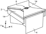
- FIG. 1 is a perspective view of an example of an accelerometer according to the invention.
- FIG. 2 is a bottom view of FIG. 1 , the cap not being represented.
- FIG. 3 is a perspective view of the accelerometer of FIG. 1 , a portion of the support being removed.
- FIG. 4 is a sectional view according to the plane A-A of FIG. 1 .
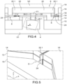
- FIG. 5 is a detail view of FIG. 3 , the nanoresonator being represented.
- FIG. 6 is a top view of FIG. 1 without the cap, the two nanoresonators being represented.
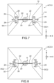
- FIG. 7 is a top view of another example of an accelerometer.
- FIG. 8 is a top view of another example of an accelerometer.
- FIG. 9 A is a perspective view of an example of an out-of-plane accelerometer.
- FIG. 9 B is a sectional view of the accelerometer of FIG. 9 A .
- FIG. 10 A is a perspective view of an example of a flowmeter.
- FIG. 10 B is a sectional view of the flowmeter of FIG. 10 A .
- FIG. 11 B is a sectional view of the flowmeter of FIG. 11 A .
- FIGS. 1 to 6 show an example of an accelerometer according to the invention partially represented.
- This accelerometer is configured to detect an acceleration in the plane.
- the accelerometer is made by microelectronics techniques by stacking and structuring layers.
- the plane of the accelerometer is defined by the directions X and Y in which the accelerometer primarily extends which are those in which the substrate and the different layers composing the accelerometer extend. In this example, it is supposed that it is desired to measure the acceleration according to the direction X.
- the accelerometer includes a support 2 , a seismic mass 4 hanging to the support 2 and means for measuring 6 ( FIGS. 4 , 5 and 6 ) the acceleration.
- the accelerometer includes a first volume V 1 within which the seismic mass 4 is accommodated, and a second volume V 2 within which the measuring means 6 are accommodated.
- the volumes V 1 and V 2 are tightly insulated from each other and at different pressures.
- the volume V 1 is at a pressure P 1 higher than the pressure P 2 of the volume V 2 .
- P 1 is at the atmospheric pressure and P 2 is at most at 10 mbar, advantageously lower than 1 mbar and even more advantageously lower than 10 ⁇ 2 mbar, and possibly the vacuum in the range of 10 ⁇ 6 mbar.
- the accelerometer includes means 8 for transmitting a force and a movement between the seismic mass and the measuring means, and by which the mass is hanging.
- FIG. 4 a sectional view of FIG. 1 can be seen.
- the accelerometer is made according to microelectronics processes from a substrate 10 referred to as “bulk”.
- the thickness of the bulk is comprised between 100 ⁇ m and 1,000 ⁇ m.
- the substrate is made of silicon.
- a stack of layers is formed over the substrate.
- the stack includes a layer 12 which forms a sacrificial layer and which contributes to sealing between the two volumes, the layer 12 is for example made of SiO 2 .
- the sacrificial layer has a thickness comprised for example between 3 ⁇ m and 5 ⁇ m.
- the stack also includes a conductive layer 14 with a nanometric thickness referred to as “nanometric layer” or “NEMS layer”.
- NEMS layer a conductive layer 14 with a nanometric thickness
- the thickness of the “NEMS layer” is comprised between 20 nm and 2 ⁇ m.
- the layer 14 is made of silicon. The layer 14 contributes to sealing between the two volumes and it is in this layer that the resonators are formed.
- the stack also includes a layer with a micrometric thickness 16 called “micrometric layer” or “MEMS layer”.
- MEMS layer a layer with a micrometric thickness 16
- the thickness of the “NEMS layer” comprised between 2 ⁇ m and 200 ⁇ m, and its thickness is selected so as to be at least twice as thick as the NEMS layer.
- an intermediate layer 18 between the NEMS layer 14 and the MEMS layer 16 is present ensuring upon manufacture the protection of the NEMS layer when structuring the MEMS layer.
- this protective layer has a thickness comprised between 1 ⁇ m and 5 ⁇ m.
- the protective layer is made of SiO 2 .
- the substrate forms a support for the accelerometer, and partially delimits the volume V 1 with the NEMS layer and the sacrificial layer which forms a sealing element between the NEMS layer and the substrate 10 .
- the sealing bead surrounds the mass.
- the volume V 2 is partially delimited by the surface of the substrate 10 covered by the sacrificial layer 12 , the NEMS layer 14 and the sacrificial layer 12 between the substrate 10 and the NEMS layer 14 . Furthermore, a cap 19 (schematically represented in dotted lines) is affixed on the stack of layers and closes the volume V 2 . In the represented example, the volume V 1 is at the atmospheric pressure and is open to the outside.
- the seismic mass 4 is formed in the substrate 10 , it has for example a planar section of 1 mm 2 ; the transmission device is formed in the sacrificial layer 12 , the MEMS layer 16 , and the intermediate layer 18 .
- the transmission device includes a transmission shaft 20 extending on either side of the NEMS layer 14 substantially in the out-of-plane direction and at least one transmission arm 22 , advantageously two in the represented example.
- the transmission shaft 20 includes a portion 20 . 1 in the volume V 1 is connected to the mass and a portion 20 . 2 in the volume V 2 is connected to the transmission arm.
- the two transmission arms 22 extend from the longitudinal end of the transmission shaft 20 located in the volume V 2 along the direction X.
- the transmission arms 22 extend along the direction X in opposite directions and each includes a longitudinal end 22 . 1 .
- the transmission shaft 20 is rotatably hinged about an axis of rotation Y 1 parallel to the direction Y by means of two beams 23 extending in the direction Y between the portion 20 . 2 of the transmission shaft and the rest of the MEMS layer 16 which surrounds the portion 20 . 1 .
- the two beams 23 are aligned and are deformable in torsion.
- the axis of rotation Y 1 is located substantially at the middle of the torsion beams in the direction Z. This rotation is made possible because of the small thickness of the NEMS layer 14 , which confers some flexibility thereon.
- the distance between the axis of rotation Y 1 and the transmission arms 22 is small so that the movement of the transmission arms is as similar as possible to a translational movement along the direction X alone.
- the centre of mass and the axis of rotation Y 1 of the transmission shaft are located in the same plane extending in the directions Y and Z.
- the mass is symmetrical with respect to a vertical plane passing through the axis of rotation and normal to the direction X.
- the transmission shaft 20 preferably has at its connection to the transmission shaft 20 an area with a reduced dimension in the direction X, which allows setting the length of the transmission arms and the dimensions of the mass independently to minimise the effect of rotation in the nanoresonators.
- This shape is not restrictive, and any other mass shape that meets the previously-described symmetry conditions will be functional, for example a mass with a circular shape or with a parallelepiped shape.
- the measuring means include two resonators 24 formed in the NEMS layer and each resonator 24 hangs between a free end 22 . 1 of a transmission arm and a fixed portion of the accelerometer.
- FIGS. 4 , 5 and 6 one can see the resonators.
- the resonators are mounted in differential.
- the sacrificial layer 12 and the rest of the NEMS layer 14 are not represented beneath and around nanoresonators for clarity, but these are nevertheless present.
- the sacrificial layer allows supporting the nanoresonators and the NEMS layer around the nanoresonators and is intended for the formation of the connection tracks of the nanoresonators, the contact pads and the decoupling means that will be described hereinbelow.
- FIG. 3 shows the NEMS layer cleared off the MEMS layer and the protective layer, the nanoresonators not being represented.
- FIG. 4 shows, represented in dotted lines, the seismic mass moved in rotation about the axis Y by the effect of an acceleration in the direction X, as well as the transmission device moved in the direction X, and the deformation of the resonators.
- the resonators are mounted in differential.
- the hinge device includes only one transmission arm and the measuring means include one single resonator.
- the measuring means also include means for setting the resonators in vibration at their resonance frequency. For example, it consists of a pair of electrodes on either side of each resonator. Furthermore, the measuring means include means for reading the variation of the resonance frequency of each resonator, for example capacitive means, piezoresistive means or piezoelectric means.
- the volume V 1 may be in communication with the external environment to set the pressure P 1 at the atmospheric pressure as is the case in the represented example.
- the pressure P 1 is lower or higher than the atmospheric pressure, and is higher than the pressure P 2 .
- An acceleration in the direction X is applied to the seismic mass 4 which is then set in rotation about the axis Y 1 ( FIG. 4 ).
- This rotation is transmitted via the transmission shaft 20 to the transmission arms 22 which move at least in translation in the direction X and apply a strain onto the resonators, one is compressed and the other is stretched.
- the transmission shaft 20 blocks the deflections in the direction Y because of the stiffness of the torsion beams in this direction.
- the resonators Prior to the acceleration, the resonators have been vibrating at a given resonance frequency. By the effect of the tensile and compressive strain, their resonance frequencies vary. The measuring means measure these frequency vibrations which allow deducing the acceleration.
- the seismic mass being accommodated within an environment at the atmospheric pressure, it is dampened.
- the movement of the mass for example in the event of an external impact, has a lower amplitude and the risks of damage or disturbance of the operation of the resonators are reduced.
- the resonators being disposed in a low-pressure environment, and possibly in vacuum, they have a high quality factor.
- the accelerometer is performant while protecting the nanoresonators from the resonance of the mass, from all vibrations of the seismic mass and from impacts applied thereon.
- FIG. 7 shows an advantageous example of an accelerometer ACC 2 according to the invention viewed from above, the cap being omitted.
- the accelerometer ACC 2 differs from the accelerometer ACC 1 in that it includes means allowing avoiding the parasitic modes of the seismic mass which degrade the operation of the sensor.
- Decoupling means DC 1 are interposed between each nanoresonator and the transmission arm connected to the mass so that the movement of the resonator at its resonance frequency in its frequency range of about one MHz or a few MHz cannot activate the parasitic modes of the mass.
- the means DC 1 include a carriage 26 with a square shape when viewed from above, fastened by one end to the free end of the transmission arm 22 and by the opposite face to a longitudinal end of the resonator 24 .
- the carriage 26 is guided in the direction X by means of two pairs of beams 28 on either side of the direction X, one end of which is anchored on the NEMS layer.
- the beams 28 are deformable in bending in the direction X.
- FIG. 8 shows an accelerometer ACC 3 including another example of decoupling means DC 2 .
- the decoupling means DC 2 include a double-lever system.
- the implementation of such a system allows for an amplification that allows compensating all or part of the sensitiveness loss that might result from the implementation of decoupling means.
- the double-lever system includes a first lever 30 and a second lever 32 , each hinged on the substrate at one point A and B respectively.
- Each lever 30 , 32 includes a large lever arm and a small lever arm.
- each of the rotational hinges is made by a beam deformable in bending anchored by one end on the NEMS layer and by another end to the lever.
- the large lever arm of the first lever 30 is connected by one end to the free end of a transmission arm 22
- the small lever arm of the first lever 30 is connected by one end to the large lever arm of the second lever 32 and the small lever arm of the second lever 32 is connected to the nanoresonator 24 .
- the force transmitted by the transmission arm 22 is amplified a first time and a second time.
- the double-lever system is symmetrical with respect to the direction X and includes two pairs of levers symmetrical with respect to the axis X.
- the sensitiveness can be amplified between 10 times and 100 times.
- FIGS. 9 A and 9 B show an embodiment of an out-of-plane accelerometer ACC 4 , i.e. measuring an acceleration according to the direction Z.
- This accelerometer ACC 4 differs from in-plane accelerometers in that the centre of mass of the seismic mass and the axis of rotation of the transmission shaft 120 are in planes extending in the distinct directions Y and Z, which results in creating a lever arm.
- the mass is then made sensitive to an out-of-plane acceleration a′, as represented in dotted lines in FIG. 9 B .
- One of the resonators 134 is stretched and the other resonator is compressed.
- the mass 104 is not symmetrical with respect to a vertical plane passing through the axis of rotation of the transmission shaft as shown in FIG. 9 B .
- the substrate 110 is structured so as to form a mass which surrounds a portion of the substrate which remains fixed.
- the mass includes an open-through passage 34 . This configuration allows making a large-sized mass.
- FIGS. 10 A and 10 B show an example of a flowmeter DB 1 implementing a force sensor according to the invention.
- the flowmeter DB 1 is suited to measure a flow in the plane of the sensor, i.e. the plane XY.
- the flowmeter DB 1 is configured so that the test body 104 is sensitive to the flow of a fluid (symbolised by the arrows FX).
- the support 102 of the flowmeter is configured to enable the flow of the fluid so that the fluid exerts a pressure on the surface 204 . 1 of the test body 204 .
- wafers are formed in the substrate 210 , for example over a portion of its height.
- test body 204 is configured so as to have a large surface that is sensitive to the flow of the fluid.
- the test body has a large dimension in the direction Y normal to the direction of the flow.
- the test body 204 has a reduced dimension in the direction X to reduce its mass.
- the sealed insulation between the two volumes protects the resonators from the fluid flowing in the volume V 2 .
- FIGS. 11 A and 11 B show another example of a flowmeter DB 2 , the latter differing from the flowmeter DB 1 in that the test body 304 is cleared so as to enable the fluid to come into contact with the lower portion of the sensitive face 304 . 1 of the test body remote from the axis of rotation of the transmission shaft.
- This clearance is obtained by etching the substrate 310 in order to reduce its thickness and let the test body 304 of the substrate 310 protrude in the direction Z.
- a test body measuring 1 mm in width, i.e. in the direction Y has a surface subjected to the pressure of the fluid of 1 mm ⁇ 0.5 mm. Thanks to an extended lever arm, this configuration allows profiting from an additional amplification.
- the measuring means include nanoresonators formed in the NEMS layer.
- the measuring means include microresonators formed in the MEMS layer. These resonators are mechanically connected to the transmission arms 22 of the transmission means.
- the measuring means include at least one piezoresistive gauge, advantageously two mounted in differential. All of the above-described examples can implement one or more piezoresistive gauge(s) instead of the resonator(s).
- the force sensor according to the invention is manufactured with the techniques of manufacturing microelectromechanical and nanoelectromechanical systems or M&NEMS (Micro&nanomicroelectromechanical systems).
- it may be manufactured using the method described in the document WO201148138.
- a Silicon on Insulate or SOI substrate including a substrate 10 made of silicon forming the bulk, a SiO 2 layer forming the sacrificial layer 12 and a monocrystalline silicon layer forming the NEMS layer.
- the NEMS layer 14 is structured in particular to form the nanoresonators.
- the protective layer 18 is formed over the NEMS layer 14 .
- the MEMS layer 16 is formed over the protective layer 18 .
- the MEMS layer 16 is structured, for example by etching, in particular to form the transmission arms 22 .
- the presence of the protective layer allows etching the MEMS layer without deteriorating the NEMS layer.
- the protective layer above the nanoresonators is suppressed.
- the nanoresonators are cleared by etching the sacrificial layer.
- Making of the transmission shaft may be done according to the following method. First of all, etching at the front face is done. For this purpose, the NEMS layer is protected over the entire area around the transmission shaft which ensures sealing. A growth of the MEMS layer at the centre of this area allows drawing the transmission shaft 20 as well as the transmission arms 22 . The protective NEMS layer is then cleared over the entirety of the sealing area of the NEMS layer except at its centre to keep the continuity of the transmission shaft 20 .
- the seismic mass is etched at the rear face. Trimming thereof is done on the bulk layer. Once the bulk layer is etched, the sacrificial layer 12 is etched in order to clear the mass except at its centre to keep the continuity of the transmission shaft 20 . Afterwards, a cap is affixed over the MEMS layer so as to form the volume V 2 . Affixing the cap is done in an environment at the pressure P 2 so that the pressure in the volume V 2 namely at the pressure P 2 .
- the transmission shaft is formed only in the MEMS layer.
Landscapes
- Physics & Mathematics (AREA)
- General Physics & Mathematics (AREA)
- Fluid Mechanics (AREA)
- Measuring Fluid Pressure (AREA)
- Force Measurement Appropriate To Specific Purposes (AREA)
Abstract
Description
Claims (18)
Applications Claiming Priority (2)
| Application Number | Priority Date | Filing Date | Title |
|---|---|---|---|
| FR2110059 | 2021-09-24 | ||
| FR2110059A FR3127566B1 (en) | 2021-09-24 | 2021-09-24 | HIGH SENSITIVITY RESONANT FORCE SENSOR WITH A TEST BODY AND AT LEAST ONE RESONANT ELEMENT DECOUPLED AND EACH ARRANGED IN A SUITABLE ENVIRONMENT |
Publications (2)
| Publication Number | Publication Date |
|---|---|
| US20230096612A1 US20230096612A1 (en) | 2023-03-30 |
| US12123792B2 true US12123792B2 (en) | 2024-10-22 |
Family
ID=81326333
Family Applications (1)
| Application Number | Title | Priority Date | Filing Date |
|---|---|---|---|
| US17/934,214 Active 2042-10-21 US12123792B2 (en) | 2021-09-24 | 2022-09-22 | Highly sensitive resonant force sensor with a test body and at least one resonant element decoupled and each disposed in a suitable environment |
Country Status (3)
| Country | Link |
|---|---|
| US (1) | US12123792B2 (en) |
| EP (1) | EP4155702A1 (en) |
| FR (1) | FR3127566B1 (en) |
Citations (5)
| Publication number | Priority date | Publication date | Assignee | Title |
|---|---|---|---|---|
| US20070022814A1 (en) * | 2005-07-27 | 2007-02-01 | Masami Seto | Semiconductor sensor |
| US20110234206A1 (en) * | 2010-03-26 | 2011-09-29 | Kabushiki Kaisha Toshiba | Acceleration sensor |
| US20150355221A1 (en) | 2009-10-23 | 2015-12-10 | Commissariat A L'energie Atomique Et Aux Energies Alternatives | In-plane piezoresistive detection sensor |
| US20200041538A1 (en) | 2018-06-19 | 2020-02-06 | Kionix, Inc. | Near-zero power wakeup electro-mechanical system |
| EP3766830A1 (en) | 2019-07-18 | 2021-01-20 | Commissariat à l'Energie Atomique et aux Energies Alternatives | Mechanical link for mechanical mems and nems structure, and mems and nems structure comprising such a mechanical link |
Family Cites Families (1)
| Publication number | Priority date | Publication date | Assignee | Title |
|---|---|---|---|---|
| GB0918484D0 (en) | 2009-10-22 | 2009-12-09 | Depuy Int Ltd | A medical implant device |
-
2021
- 2021-09-24 FR FR2110059A patent/FR3127566B1/en active Active
-
2022
- 2022-09-14 EP EP22195544.6A patent/EP4155702A1/en active Pending
- 2022-09-22 US US17/934,214 patent/US12123792B2/en active Active
Patent Citations (6)
| Publication number | Priority date | Publication date | Assignee | Title |
|---|---|---|---|---|
| US20070022814A1 (en) * | 2005-07-27 | 2007-02-01 | Masami Seto | Semiconductor sensor |
| US20150355221A1 (en) | 2009-10-23 | 2015-12-10 | Commissariat A L'energie Atomique Et Aux Energies Alternatives | In-plane piezoresistive detection sensor |
| US20110234206A1 (en) * | 2010-03-26 | 2011-09-29 | Kabushiki Kaisha Toshiba | Acceleration sensor |
| US20200041538A1 (en) | 2018-06-19 | 2020-02-06 | Kionix, Inc. | Near-zero power wakeup electro-mechanical system |
| EP3766830A1 (en) | 2019-07-18 | 2021-01-20 | Commissariat à l'Energie Atomique et aux Energies Alternatives | Mechanical link for mechanical mems and nems structure, and mems and nems structure comprising such a mechanical link |
| US20210018378A1 (en) | 2019-07-18 | 2021-01-21 | Commissariat A L'energie Atomique Et Aux Energies Alternatives | Mechanical link for mems and nems mechanical structure, and mems and nems structure comprising such a mechanical link |
Non-Patent Citations (5)
| Title |
|---|
| Ding et al., "A high-sensitivity biaxial resonant accelerometer with two-stage microleverage mechanisms", Journal of Micromechanics and Microengineering, 2016, 12 pages. |
| French Preliminary Search Report issued Jul. 27, 2022 in French Application 21 10059 filed on Sep. 24, 2021, 2 pages (with English Translation of Categories of Cited Documents). |
| Martin et al., "Strain Gauge Pressure and Volume-Flow Transducers Made by Thermoplastic Molding and Membrane Transfer", IEEE, 1998, 6 pages. |
| Mustafazade et al., "A vibrating beam MEMS accelerometer for gravity and seismic measurements", Scientific Reports, 2020, 8 pages. |
| Yucetas et al., "A High-Resolution Accelerometer With Electrostatic Damping and Improved Supply Sensitivity", IEEE Journal of Solid-State Circuits, vol. 47, No. 7, Jul. 2012, 10 pages. |
Also Published As
| Publication number | Publication date |
|---|---|
| FR3127566B1 (en) | 2023-11-17 |
| EP4155702A1 (en) | 2023-03-29 |
| FR3127566A1 (en) | 2023-03-31 |
| US20230096612A1 (en) | 2023-03-30 |
Similar Documents
| Publication | Publication Date | Title |
|---|---|---|
| US6484578B2 (en) | Vibrating beam accelerometer | |
| JP5825899B2 (en) | MEMS dynamic pressure sensor with special application to microphone manufacturing | |
| JP6053357B2 (en) | Pressure measuring device with optimized sensitivity | |
| US5996411A (en) | Vibrating beam accelerometer and method for manufacturing the same | |
| US6662658B2 (en) | Whiffletree accelerometer | |
| US8616059B2 (en) | Force sensor with reduced noise | |
| US6634231B2 (en) | Accelerometer strain isolator | |
| US6311556B1 (en) | Micro-accelerometer with capacitive resonator | |
| US20100089157A1 (en) | Micro-Machined Accelerometer | |
| JP2014512518A (en) | Inertial sensor assembly method | |
| US7104128B2 (en) | Multiaxial micromachined differential accelerometer | |
| EP3835794B1 (en) | Resonator including one or more mechanical beams with added mass | |
| JP5121765B2 (en) | MEMS device and manufacturing method thereof | |
| Miani et al. | Resonant accelerometers based on nanomechanical piezoresistive transduction | |
| US20020050167A1 (en) | Net zero isolator | |
| KR102668056B1 (en) | Sensor packages | |
| US12123792B2 (en) | Highly sensitive resonant force sensor with a test body and at least one resonant element decoupled and each disposed in a suitable environment | |
| CN113029321B (en) | Capacitive MEMS vector acoustic wave sensor capable of inhibiting vibration interference and processing method thereof | |
| JP6044607B2 (en) | Vibration sensor device | |
| Fain et al. | High-damped accelerometer based on squeeze-film damping and piezoresistive nanogauge detection for vibrating environments | |
| EP1034434B1 (en) | Vibrating beam accelerometer | |
| Maiwald et al. | Shoaling vibration amplifier with flattened transfer function and suppressed spurious modes | |
| US20200199923A1 (en) | Out-of-plane hinge for micro and nanoelectromechanical systems with reduced non-linearity | |
| Müller et al. | Two-level bulk microfabrication of a mechanical broadband vibration amplitude-amplifier with ten coupled resonators |
Legal Events
| Date | Code | Title | Description |
|---|---|---|---|
| FEPP | Fee payment procedure |
Free format text: ENTITY STATUS SET TO UNDISCOUNTED (ORIGINAL EVENT CODE: BIG.); ENTITY STATUS OF PATENT OWNER: LARGE ENTITY |
|
| STPP | Information on status: patent application and granting procedure in general |
Free format text: DOCKETED NEW CASE - READY FOR EXAMINATION |
|
| AS | Assignment |
Owner name: COMMISSARIAT A L'ENERGIE ATOMIQUE ET AUX ENERGIES ALTERNATIVES, FRANCE Free format text: ASSIGNMENT OF ASSIGNORS INTEREST;ASSIGNORS:MIANI, THEO;SANSA PERNA, MARC;REEL/FRAME:061896/0871 Effective date: 20221014 |
|
| STPP | Information on status: patent application and granting procedure in general |
Free format text: NON FINAL ACTION MAILED |
|
| STPP | Information on status: patent application and granting procedure in general |
Free format text: RESPONSE TO NON-FINAL OFFICE ACTION ENTERED AND FORWARDED TO EXAMINER |
|
| STPP | Information on status: patent application and granting procedure in general |
Free format text: NOTICE OF ALLOWANCE MAILED -- APPLICATION RECEIVED IN OFFICE OF PUBLICATIONS |
|
| ZAAB | Notice of allowance mailed |
Free format text: ORIGINAL CODE: MN/=. |
|
| STPP | Information on status: patent application and granting procedure in general |
Free format text: PUBLICATIONS -- ISSUE FEE PAYMENT VERIFIED |
|
| STCF | Information on status: patent grant |
Free format text: PATENTED CASE |