US12123789B2 - Method and device for temperature detection and thermal management based on power measurement - Google Patents
Method and device for temperature detection and thermal management based on power measurement Download PDFInfo
- Publication number
- US12123789B2 US12123789B2 US17/366,348 US202117366348A US12123789B2 US 12123789 B2 US12123789 B2 US 12123789B2 US 202117366348 A US202117366348 A US 202117366348A US 12123789 B2 US12123789 B2 US 12123789B2
- Authority
- US
- United States
- Prior art keywords
- temperature
- circuit
- power
- period
- electric circuit
- Prior art date
- Legal status (The legal status is an assumption and is not a legal conclusion. Google has not performed a legal analysis and makes no representation as to the accuracy of the status listed.)
- Active, expires
Links
Images


Classifications
-
- G—PHYSICS
- G01—MEASURING; TESTING
- G01K—MEASURING TEMPERATURE; MEASURING QUANTITY OF HEAT; THERMALLY-SENSITIVE ELEMENTS NOT OTHERWISE PROVIDED FOR
- G01K7/00—Measuring temperature based on the use of electric or magnetic elements directly sensitive to heat ; Power supply therefor, e.g. using thermoelectric elements
- G01K7/42—Circuits effecting compensation of thermal inertia; Circuits for predicting the stationary value of a temperature
- G01K7/425—Thermal management of integrated systems
-
- G—PHYSICS
- G05—CONTROLLING; REGULATING
- G05D—SYSTEMS FOR CONTROLLING OR REGULATING NON-ELECTRIC VARIABLES
- G05D23/00—Control of temperature
- G05D23/19—Control of temperature characterised by the use of electric means
-
- G—PHYSICS
- G06—COMPUTING OR CALCULATING; COUNTING
- G06F—ELECTRIC DIGITAL DATA PROCESSING
- G06F1/00—Details not covered by groups G06F3/00 - G06F13/00 and G06F21/00
- G06F1/16—Constructional details or arrangements
- G06F1/20—Cooling means
- G06F1/206—Cooling means comprising thermal management
-
- G—PHYSICS
- G06—COMPUTING OR CALCULATING; COUNTING
- G06F—ELECTRIC DIGITAL DATA PROCESSING
- G06F1/00—Details not covered by groups G06F3/00 - G06F13/00 and G06F21/00
- G06F1/26—Power supply means, e.g. regulation thereof
- G06F1/32—Means for saving power
- G06F1/3203—Power management, i.e. event-based initiation of a power-saving mode
- G06F1/3206—Monitoring of events, devices or parameters that trigger a change in power modality
-
- G—PHYSICS
- G06—COMPUTING OR CALCULATING; COUNTING
- G06F—ELECTRIC DIGITAL DATA PROCESSING
- G06F1/00—Details not covered by groups G06F3/00 - G06F13/00 and G06F21/00
- G06F1/26—Power supply means, e.g. regulation thereof
- G06F1/32—Means for saving power
- G06F1/3203—Power management, i.e. event-based initiation of a power-saving mode
- G06F1/3234—Power saving characterised by the action undertaken
- G06F1/3296—Power saving characterised by the action undertaken by lowering the supply or operating voltage
-
- G—PHYSICS
- G06—COMPUTING OR CALCULATING; COUNTING
- G06F—ELECTRIC DIGITAL DATA PROCESSING
- G06F11/00—Error detection; Error correction; Monitoring
- G06F11/30—Monitoring
- G06F11/3058—Monitoring arrangements for monitoring environmental properties or parameters of the computing system or of the computing system component, e.g. monitoring of power, currents, temperature, humidity, position, vibrations
-
- G—PHYSICS
- G06—COMPUTING OR CALCULATING; COUNTING
- G06F—ELECTRIC DIGITAL DATA PROCESSING
- G06F1/00—Details not covered by groups G06F3/00 - G06F13/00 and G06F21/00
- G06F1/26—Power supply means, e.g. regulation thereof
- G06F1/28—Supervision thereof, e.g. detecting power-supply failure by out of limits supervision
-
- G—PHYSICS
- G06—COMPUTING OR CALCULATING; COUNTING
- G06F—ELECTRIC DIGITAL DATA PROCESSING
- G06F1/00—Details not covered by groups G06F3/00 - G06F13/00 and G06F21/00
- G06F1/26—Power supply means, e.g. regulation thereof
- G06F1/32—Means for saving power
- G06F1/3203—Power management, i.e. event-based initiation of a power-saving mode
- G06F1/3234—Power saving characterised by the action undertaken
- G06F1/3237—Power saving characterised by the action undertaken by disabling clock generation or distribution
-
- G—PHYSICS
- G06—COMPUTING OR CALCULATING; COUNTING
- G06F—ELECTRIC DIGITAL DATA PROCESSING
- G06F1/00—Details not covered by groups G06F3/00 - G06F13/00 and G06F21/00
- G06F1/26—Power supply means, e.g. regulation thereof
- G06F1/32—Means for saving power
- G06F1/3203—Power management, i.e. event-based initiation of a power-saving mode
- G06F1/3234—Power saving characterised by the action undertaken
- G06F1/324—Power saving characterised by the action undertaken by lowering clock frequency
-
- G—PHYSICS
- G06—COMPUTING OR CALCULATING; COUNTING
- G06F—ELECTRIC DIGITAL DATA PROCESSING
- G06F11/00—Error detection; Error correction; Monitoring
- G06F11/30—Monitoring
- G06F11/3058—Monitoring arrangements for monitoring environmental properties or parameters of the computing system or of the computing system component, e.g. monitoring of power, currents, temperature, humidity, position, vibrations
- G06F11/3062—Monitoring arrangements for monitoring environmental properties or parameters of the computing system or of the computing system component, e.g. monitoring of power, currents, temperature, humidity, position, vibrations where the monitored property is the power consumption
-
- G—PHYSICS
- G06—COMPUTING OR CALCULATING; COUNTING
- G06F—ELECTRIC DIGITAL DATA PROCESSING
- G06F2123/00—Data types
- G06F2123/02—Data types in the time domain, e.g. time-series data
-
- G—PHYSICS
- G06—COMPUTING OR CALCULATING; COUNTING
- G06N—COMPUTING ARRANGEMENTS BASED ON SPECIFIC COMPUTATIONAL MODELS
- G06N20/00—Machine learning
-
- Y—GENERAL TAGGING OF NEW TECHNOLOGICAL DEVELOPMENTS; GENERAL TAGGING OF CROSS-SECTIONAL TECHNOLOGIES SPANNING OVER SEVERAL SECTIONS OF THE IPC; TECHNICAL SUBJECTS COVERED BY FORMER USPC CROSS-REFERENCE ART COLLECTIONS [XRACs] AND DIGESTS
- Y02—TECHNOLOGIES OR APPLICATIONS FOR MITIGATION OR ADAPTATION AGAINST CLIMATE CHANGE
- Y02D—CLIMATE CHANGE MITIGATION TECHNOLOGIES IN INFORMATION AND COMMUNICATION TECHNOLOGIES [ICT], I.E. INFORMATION AND COMMUNICATION TECHNOLOGIES AIMING AT THE REDUCTION OF THEIR OWN ENERGY USE
- Y02D10/00—Energy efficient computing, e.g. low power processors, power management or thermal management
Definitions
- the inventive concept relates to thermal management of a device, and more particularly, to a method and a device for temperature detection and device thermal management based on power measurement.
- User devices may include one or more integrated circuits (ICs) to perform various processing operations for user device functionality.
- An IC may include one or more electronic circuits located on a chip, called a system-on-chip.
- ICs are used to perform computer processing and calculations related to an input to a computer (e.g., ICs may perform processing operations in response to user input).
- Mobile phones, computers, GPS devices, and tablets may use ICs for processing, storage, and computer calculations, among other uses.
- ICs include temperature sensors that are used to determine the temperate of components of the IC.
- a temperature sensor may be a small device that is used to detect a surface temperature of an IC or a core (e.g., inner) temperature of an IC. In some cases, a temperature sensor may detect a combination of surface temperatures and core temperatures of an IC. The sensed temperature may then be used to adjust the temperature the IC with the use of fans, fluid, or power reduction, among other temperature control methods.
- power applied to the IC may influence the temperature of the IC. Therefore, power input and output of an IC can be monitored (e.g., and power input and output may be adjusted to adjust the temperature of the IC).
- a power monitor may measure the input power of an IC, the output power of an IC, or both. Dynamic power monitoring techniques may be implemented to determine power levels periodically, over time, where the timing of the monitoring may be adjusted based on a user's preferences.
- the temperature of the IC may become undesirable or unstable, which may cause damage to the IC or the user device. For example, if temperatures reach a threshold higher than a casing around a lithium-ion battery, the battery may be exposed to a moist atmosphere, resulting is an explosion. Therefore, there is a need in the art to periodically sense and accurately control the temperature of an IC.
- the inventive concept provides a method and a device for accurately detecting a temperature based on power measurement and optimally controlling a temperature of a device based on power and a temperature.
- a device including a first circuit configured to operate based on first input signals; a first power monitor configured to measure a first power of the first circuit according to a first period, wherein the first power of the first circuit is measured based on the first input signals; a temperature sensor configured to sense temperature of the device according to a second period; and a controller configured to estimate a first temperature of the first circuit according to the first period, receive a second temperature from the temperature sensor according to the second period, calculate a third temperature based on (e.g., by correcting) the first temperature and the second temperature, and determine a circuit temperature of the first circuit according to the first period based at least in part on the first temperature and the third temperature, wherein the first period is shorter than the second period.
- a method including measuring a first power of a first circuit based on input signals of the first circuit in a first period; estimating a first temperature of the first circuit based on the first power; calculating a third temperature by sensing a second temperature of a device including the first circuit and correcting the first temperature based on the second temperature in a second period; and determining a circuit temperature of the first circuit based on the first temperature and the third temperature in one or more instances of the first period, wherein the first period is shorter than the second period.
- a device including at least one circuit configured to operate based on input signals; at least one power monitor configured to measure power of the at least one circuit based on the input signals; at least one temperature sensor configured to sense temperature of the device; and a controller configured to estimate a first temperature of the at least one circuit based on the measured power, calculate a third temperature by correcting the first temperature based on a second temperature sensed by the temperature sensor, and control a temperature of the at least one circuit based on the measured power, the first temperature, and the third temperature.
- a method including estimating temperatures of a circuit at first time intervals according to a first period, wherein the temperatures are estimated at the first time intervals based on power consumed by the circuit; receiving temperature measurements of the circuit from a temperature sensor at second time intervals according to a second period longer than the first period; adjusting at least one of the estimated temperatures based on at least one of the received temperature measurements; and determining whether circuit temperature of the circuit satisfies a threshold at each of the first time intervals according to the first period, wherein the determination at one of the first time intervals is based on the at least one adjusted estimated temperatures.
- FIG. 1 is a block diagram showing a device according to an example embodiment
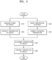
- FIG. 2 is a flowchart of a method for temperature detection and thermal management according to an example embodiment
- FIG. 3 is a message diagram showing a method of detecting a temperature according to an example embodiment
- FIG. 4 is a diagram showing a method of detecting a temperature according to an example embodiment
- FIG. 5 is a diagram showing a look-up table according to an example embodiment
- FIG. 6 is a block diagram showing a device according to an example embodiment
- FIG. 7 is a flowchart of a method of detecting a temperature according to an example embodiment
- FIG. 8 is a block diagram showing a device according to an example embodiment
- FIG. 9 is a diagram showing a method for thermal management according to an example embodiment
- FIGS. 10 A and 10 B are graphs showing changes in power and temperature of a circuit over time
- FIG. 11 is a flowchart of a method of detecting a temperature according to an example embodiment
- FIG. 12 is a flowchart of a method of detecting a temperature according to an example embodiment
- FIG. 13 is a block diagram showing a device according to an example embodiment.
- FIG. 14 is a block diagram showing a system according to an example embodiment.
- User devices may include one or more integrated circuits (ICs) to perform various processing operations for user device functionality.
- An IC may include one or more electronic circuits located on a chip, called a system-on-chip.
- ICs are used to perform computer processing and calculations related to an input to a computer (e.g., ICs may perform processing operations in response to user input).
- Mobile phones, computers, GPS devices, and tablets may use ICs for processing, storage, and computer calculations, among other uses.
- ICs include temperature sensors that are used to determine the temperate of components of the IC.
- a temperature sensor may be included in the IC.
- a temperature sensor may detect a temperature based on a temperature characteristic of an element.
- such temperature sensors may detect a temperature at according to a relatively long period (e.g., temperature sensors may monitor temperature less frequently than may be desirable).
- a temperature sensor may detect the temperature of a chip or IC at certain periods of time. The time periods may be extended (e.g., based on device settings, performance targets, etc.), supplying less frequent temperature information to control the temperature. Therefore, when the temperature of an IC is controlled based on a temperature sensed by a temperature sensor, the performance of the IC may be limited (e.g., due to excessive temperatures).
- the present disclosure relates generally to a device and method for sensing a temperature of an IC. More particularly, embodiments of the present disclosure relate to a device and method for estimating and correcting a temperature of an IC.
- the present disclosure estimates a temperature based on power measured by a dynamic power monitor (DPM).
- the estimated temperature may be corrected based on a temperature sensed by a temperature sensor on the IC.
- the power may be measured in shorter time periods and/or more frequent time periods compared to a traditional temperature sensor. Accordingly, the temperature of an IC may be detected and adjusted more frequently. Such may provide for finer control of IC temperature and may reduce a performance margin to comply with device temperature limits.
- Embodiments of the present disclosure include a device and methods used to control a temperature of an IC.
- the device may include a circuit (e.g., an IC), a power monitor, a temperature sensor, and a controller.
- the device may estimate a first temperature of a circuit at a first time interval of a first period, where the first temperature is estimated based on power consumed by the circuit.
- the device may further receive a temperature measurement of the circuit from a temperature sensor at a first time interval of a second period, where the second period is longer than the first period. Accordingly, the device may estimate a second temperature of the circuit at a second time interval of the first period and adjust the second estimated temperature based on the received temperature measurement.
- the device may determine, according to a periodicity having the shorter or reduced first period, whether circuit temperature should be adjusted.
- FIG. 1 is a block diagram showing a device 10 according to an example embodiment.
- the device 10 may include an electric circuit 11 , a power monitor 12 , a temperature sensor 13 , a voltage generator 14 , a clock generator 15 , and a thermal controller 16 .
- the device 10 may refer to any device that includes a heat-emitting component (e.g., 13 ).
- the device 10 may be an electronic system like a computing system, a memory system, a communication system, and a network system or a component included in the electronic system.
- the device 10 may be an IC manufactured through a semiconductor process, and components of the device 10 may be included in at least one package.
- the electric circuit 11 may operate based on an input signal IN.
- the electric circuit 11 may be a processing circuit configured to process a digital signal and/or an analog signal.
- the electric circuit 11 may include at least one of a programmable component like a central processing unit (CPU), a graphics processing unit (GPU), a neural processing unit (NPU), a component providing a fixed function like an intellectual property (IP) core, and a reconfigurable component like a field-programmable gate array (FPGA).
- the electric circuit 11 may be a circuit block included in one of the above-described components.
- the electric circuit 11 may receive a positive supply voltage VDD (may also be referred to as a supply voltage herein) from the voltage generator 14 and receive a clock signal CLK from the clock generator 15 .
- the electric circuit 11 may use power provided through the positive supply voltage VDD and may operate in synchronization with the clock signal CLK. Therefore, the power consumption of the electric circuit 11 may depend on the positive supply voltage VDD and the clock signal CLK. For example, the power consumption of the electric circuit 11 may increase as the positive supply voltage VDD increases and may increase as the frequency of the clock signal CLK increases.
- the electric circuit 11 may be referred to as a circuit.
- the power consumption of the electric circuit 11 may be used to estimate temperature of the electric circuit 11 (e.g., where more power consumed may be indicative of higher temperatures). As electric circuit 11 operates, it generates heat. For example, the temperature of the electric circuit 11 may depend on the power consumption of the electric circuit 11 , such that the temperature of the electric circuit 11 may increase based on processing large data loads, performing complex operations, processing speed (e.g., clock signal CLK frequency), etc. As such, power estimates may be used to estimate temperature of the electric circuit (e.g., where the temperature estimates may be adjusted based on any temperature measurements received from a temperature sensor 13 , as described in more detail herein).
- a method of thermal management may include estimating a first temperature of a circuit at a first time interval of a first period, wherein the first temperature is estimated based on power consumed by the circuit; receiving a temperature measurement of the circuit from a temperature sensor at a first time interval of a second period, wherein the second period is longer than the first period; estimating a second temperature of the circuit at a second time interval of the first period, wherein the second temperature is estimated based on power consumed by the circuit adjusting the second estimated temperature based on the received temperature measurement; and determining, according to a periodicity having the first period, whether circuit temperature of the circuit satisfies a threshold based at least in part on the estimated first temperature and the adjusted second estimated temperature.
- the power monitor 12 may receive an input signal IN provided to the electric circuit 11 and measure the power consumed by the electric circuit 11 based on the input signal IN.
- the power monitor 12 may include a dynamic power monitor (DPM) disclosed in U.S. patent application Ser. No. 15/931,043, filed by the same applicant as the present application and incorporated herein by reference in its entirety.
- DPM dynamic power monitor
- the power monitor 12 may receive a clock gating signal and/or an enable signal as the input signal IN.
- the power monitor 12 may accurately and quickly measure the power consumed by the electric circuit 11 based on a clock gating signal and/or an enable signal that determines the power consumption of the electric circuit 11 .
- the power monitor 12 may provide information regarding measured power (i.e., power information PWR) to the thermal controller 16 .
- the temperature sensor 13 may sense the ambient temperature of the electric circuit 11 and may provide information regarding the sensed temperature (i.e., temperature information TMP) to the thermal controller 16 .
- providing temperature information e.g., TMP
- TMP temperature information
- the temperature sensor 13 may be provided inside the electric circuit 11 in some embodiments and may be provided around the electric circuit 11 in some other embodiments.
- the temperature sensor 13 may have an arbitrary structure for sensing a temperature. For example, temperature sensor 13 may detect a temperature by detecting a characteristic of an element that varies according to temperatures. Due to temperature sensing based on the characteristics of an element, as described later with reference to FIG.
- a period in which the temperature sensor 13 provides the temperature information TMP to the thermal controller 16 may be longer than a period in which the power monitor 12 provides the power information PWR to the thermal controller 16 (may be referred to as a first period herein).
- a period may generally refer to a frequency in which time instances repeat.
- a time period may refer to the time taken for a complete cycle to occur.
- a period may refer to the time between two measurements to be taken (e.g., by a temperature sensor or a power monitor), the time between two calculations (e.g., the time between a first temperature estimate and a second temperature estimate, the time between temperature control determinations, etc.), among other examples.
- the thermal controller 16 may receive the power information PWR from the power monitor 12 and may receive the temperature information TMP of the device 10 from the temperature sensor 13 .
- the thermal controller 16 may estimate the temperature of the electric circuit 11 based on the power information PWR and correct an estimated temperature based on the temperature information TMP.
- the thermal controller 16 may estimate a temperature based on the power information PWR, and, when the temperature information TMP is received, correct an estimated temperature.
- the thermal controller 16 may determine the temperature of the electric circuit 11 based on an estimated temperature and a corrected temperature. Accordingly, the thermal controller 16 may more frequently detect an exact temperature of the electric circuit 11 .
- the thermal controller 16 may control the temperature of the electric circuit 11 based on a detected temperature of the electric circuit 11 . For example, when the detected temperature of the electric circuit 11 is low, the thermal controller 16 may increase the performance of the electric circuit 11 by increasing power consumption by the electric circuit 11 . Additionally, or alternatively, when the detected temperature of the electric circuit 11 is high, the thermal controller 16 may limit the performance of the electric circuit 11 by reducing the power consumption by the electric circuit 11 . As shown in FIG. 1 , the thermal controller 16 may control the voltage generator 14 and adjust the magnitude of the positive supply voltage VDD, through a first control signal CTR 1 . Additionally, or alternatively, the thermal controller 16 may control the clock generator 15 and adjust the frequency of the clock signal CLK, through a second control signal CTR 2 .
- Controlling a temperature and/or power consumption by adjusting the magnitude of a supply voltage and the clock frequency as described above may be referred to as dynamic voltage frequency scaling (DVFS).
- DVFS dynamic voltage frequency scaling
- the thermal controller 16 may frequently detect an exact temperature of the electric circuit 11 , thereby finely controlling the temperature of the electric circuit 11 in the time axis. As a result, the electric circuit 11 may provide optimum performance in a limited temperature range.
- the thermal controller 16 may have any structure for performing the above-described operations.
- the thermal controller 16 may include a processor configured to execute instructions and a memory for storing a series of instructions.
- the thermal controller 16 may include a state machine and may include an IP core that provides fixed functionality designed by logic synthesis and/or a reconfigurable logic circuit like an FPGA.
- the thermal controller 16 may be referred to as a controller.
- FIG. 2 is a flowchart of a method for temperature detection and thermal management according to an example embodiment.
- the method for temperature detection and thermal management may include a plurality of operations (operations S 10 to S 60 ), and operations S 10 and S 20 may be performed in parallel with operations S 30 and S 40 .
- the method of FIG. 2 may be performed by the device 10 of FIG. 1 , and FIG. 2 will be described below with reference to FIG. 1 .
- the power of a circuit may be measured in operation S 10 .
- the power monitor 12 may measure power consumed by the electric circuit 11 based on an input signal IN provided to the electric circuit 11 .
- the power monitor 12 may periodically measure power and provide power information PWR representing the measured power to the thermal controller 16 .
- An example of operation S 10 will be described later with reference to FIG. 11 .
- a temperature of the circuit may be estimated.
- the temperature of the electric circuit 11 may depend on the power consumption of the electric circuit 11 . Therefore, the thermal controller 16 may estimate the temperature of the electric circuit 11 based on the power information PWR provided from the power monitor 12 .
- a temperature estimated based on the power information PWR may be referred to as a first temperature. Examples of an operation for estimating a temperature based on the power information PWR will be described later with reference to FIGS. 4 , 5 , and 6 .
- the temperature of a device may be sensed.
- the temperature sensor 13 may be included in the device 10 including the electric circuit 11 and may sense the ambient temperature of the electric circuit 11 .
- the temperature sensor 13 may periodically sense a temperature and may provide the temperature information TMP representing the measured temperature to the thermal controller 16 .
- a temperature sensed by the temperature sensor 13 may be referred to as a second temperature.
- the estimated temperature may be corrected.
- the thermal controller 16 may receive the power information PWR more frequently than the temperature information TMP. Therefore, the temperature of the electric circuit 11 may be estimated every time the power information PWR is received.
- a temperature sensed by the temperature sensor 13 may have high reliability, and the thermal controller 16 may correct a temperature estimated based on the power information PWR based on the temperature information TMP. Therefore, an error of the temperature estimated based on the power information PWR may be eliminated.
- a temperature corrected based on the temperature information TMP from a temperature estimated based on the power information PWR may be referred to as a third temperature.
- the temperature of the circuit may be determined.
- the thermal controller 16 may determine the temperature of the electric circuit 11 based on a temperature estimated in operation S 20 (i.e., the first temperature) and a temperature corrected in operation S 40 (i.e., the third temperature).
- the thermal controller 16 may determine a temperature estimated based on the power information PWR as the temperature of the electric circuit 11 until the temperature information TMP is received, and, when the temperature information TMP is received, a temperature corrected from the estimated temperature may be determined as the temperature of the electric circuit 11 .
- a temperature determined by the thermal controller 16 may be referred to as a detected temperature of the electric circuit 11 .
- An example of operation S 50 will be described later with reference to FIG. 7 .
- FIG. 3 is a message diagram showing a method of detecting a temperature according to an example embodiment.
- the message diagram of FIG. 3 shows messages provided to a thermal controller 36 from a power monitor 32 and a temperature sensor 33 and operations of the thermal controller 36 over time.
- the power monitor 32 may measure the power of the circuit (e.g., 11 of FIG. 1 ) and the temperature sensor 33 may sense the ambient temperature of the corresponding circuit.
- the power monitor 32 may provide the power information PWR to the thermal controller 36 in every first period PER 1
- the temperature sensor 33 may provide the temperature information TMP to the thermal controller 36 in every second period PER 2 , the second period PER 2 being longer than the first period PER 1
- a power monitor 32 may be configured to measure a first power of the first circuit according to a first period (e.g., power monitor 32 may measure power information PWR in every first period PER 1 according to the first period PER 1 ).
- the power monitor 32 may estimate power based on an input signal provided to the circuit, and the first period PER 1 may be within the range from several ns (nanoseconds) to hundreds of ns. Additionally, or alternatively, as described above with reference to FIG. 1 , the temperature sensor 33 may sense a temperature based on the characteristics of an element, and the second period PER 2 may be within the range from several ⁇ s (microseconds) to hundreds of ⁇ s. Therefore, as described later, the thermal controller 36 may estimate the temperature of the circuit for each first period PER 1 and correct an estimated temperature for each second period PER 2 . In some embodiments, the first period PER 1 may vary.
- the power monitor 32 may operate in synchronization with a clock signal (e.g., CLK of FIG. 1 ) provided to the circuit. Therefore, when the thermal controller 36 adjusts the frequency of the clock signal to control the temperature of the circuit, the operation speed of the power monitor 12 may fluctuate, and the first period PER 1 may vary.
- a clock signal e.g., CLK of FIG. 1
- the power monitor 32 may provide the power information PWR to the thermal controller 36 , and, in operation S 1 , the thermal controller 36 may estimate the temperature of the circuit based on the power information PWR received in operation S 0 .
- the power monitor 32 may provide new power information PWR to the thermal controller 36 in operation S 2 .
- the thermal controller 36 may estimate the temperature of the circuit based on the power information PWR received in operation S 2 . Therefore, the thermal controller 36 may detect the temperature of the circuit in every first period PER 1 , the first period PER 1 being shorter than the second period PER 2 .
- the temperature sensor 33 may provide the temperature information TMP to the thermal controller 36 , and, in operation S 5 , the thermal controller 36 may correct the temperature estimated in operation S 3 based on the temperature information TMP.
- estimation of a temperature (e.g., T EST of FIG. 4 ) based on the power information PWR may be based on a previously estimated temperature (e.g., T EST ′). Therefore, an error of an estimated temperature may propagate to subsequently estimated temperatures.
- the thermal controller 36 may correct a temperature estimated based on the power information PWR in every second period PER 2 based on the temperature information TMP provided from the temperature sensor 33 . Therefore, propagation of errors of an estimated temperature may be prevented.
- the power monitor 32 may provide the power information PWR to the thermal controller 36 , and, in operation S 7 , the thermal controller 36 may estimate the temperature of the circuit based on the power information PWR received in operation S 6 .
- the thermal controller 36 may estimate the temperature of the circuit based on the temperature corrected in operation S 5 , instead of the temperature estimated in operation S 3 .
- the temperature sensor 33 may provide new temperature information TMP to the thermal controller 36 in operation S 8 .
- the thermal controller 36 may correct, based on the temperature information TMP received in operation S 8 , a temperature estimated before operation S 8 .
- inventions of the present disclosure include a device and methods used to control a temperature of an IC.
- the device includes a first circuit, a power monitor 32 , a temperature sensor 33 , and a controller 36 .
- the first circuit is configured to operate based on first input signals.
- the power monitor 32 is configured to measure first power of the first circuit based on the first input signals in every first period (e.g., at S 1 , S 3 , etc.).
- the temperature sensor 33 is configured to sense a temperature of the device in every second period (e.g., at S 4 , S 8 , etc.).
- the controller 36 is configured to estimate a first temperature of the first circuit in every first period, receive a second temperature from the temperature sensor in every second period, calculate a third temperature by correcting the first temperature based on the second temperature, and determine the temperature of the first circuit based on the first temperature and the third temperature in every first period.
- the first period may be shorter than the second period.
- the controller 36 may calculate a third temperature (e.g., at S 5 ) by correcting the first temperature (e.g., from S 3 ) based on the second temperature (e.g., from S 4 ).
- FIG. 4 is a diagram showing a method of detecting a temperature according to an example embodiment.
- FIG. 4 schematically shows an operation of estimating a temperature T EST based on measured power P MEA of the electric circuit 11 , identified by the thermal controller 16 of FIG. 1 from the power information PWR, by using operators.
- an operator Z ⁇ 1 may correspond to a unit delay and may provide a value input in a previous estimation operation.
- the thermal controller 16 may include hardware components corresponding to operators shown in FIG. 4 , e.g., adders, multipliers, and buffers. Additionally, or alternatively, in some embodiments, the thermal controller 16 may sequentially perform operations corresponding to the operators shown in FIG. 4 by executing a series of instructions.
- n is a positive integer and may be a variable that increases according to the number of estimations (or the number of times of reception of the power information PWR).
- P MEA (n) is a currently measured power (for example, a value included in currently received power information PWR) and may correspond to P MEA of FIG. 4 .
- P MEA (n ⁇ 1) is previously measured power (for example, a value included in previously received power information PWR) and may correspond to P MEA ′ of FIG. 4 .
- T EST (n) is a currently estimated temperature and may correspond to T EST of FIG. 4 .
- T EST (n ⁇ 1) is a previously estimated temperature and may correspond to T EST ′ of FIG. 4 .
- Equation 1 a 1 and a 2 are coefficients, and the thermal controller 16 may obtain a1 and a2 in various ways. Examples in which the thermal controller 16 obtains a 1 and a 2 will be described later with reference to FIGS. 5 and 6 .
- the currently estimated temperature T EST may be calculated based on the previously estimated temperature T EST ′. Therefore, when the estimated temperature T EST has an error, the error may propagate to subsequently estimated temperatures. However, as described above with reference to FIG. 3 , the thermal controller 16 may correct T EST periodically (for example, in every second period PER 2 ) based on the highly reliable temperature information TMP provided from the temperature sensor 13 , thereby preventing propagation of errors.
- FIG. 5 is a diagram showing a look-up table 50 according to an example embodiment.
- FIG. 5 shows the look-up table 50 providing the coefficients of FIG. 4 .
- a 1 and a 2 For example, a 1 and a 2 .
- FIG. 5 will be described with reference to FIG. 1 .
- the device 10 of FIG. 1 may include the look-up table 50 of FIG. 5 .
- the device 10 may include a non-volatile memory that does not lose data even when power supply is cut off (e.g., flash memory, one-time programmable (OTP) memory, etc.), and the look-up table 50 may be stored in the non-volatile memory.
- the thermal controller 16 may obtain a 1 and a 2 of FIG. 4 from the look-up table 50 by accessing the non-volatile memory.
- values of a 1 and a 2 included in the look-up table 50 may be determined by testing the device 10 and may be externally applied during a manufacturing process of the device 10 .
- the look-up table 50 may include values of a 1 and a 2 corresponding to a plurality of combinations of operation parameters of the electric circuit 11 .
- the look-up table 50 may include values of a 1 and a 2 corresponding to a plurality of combinations of the positive supply voltage VDD and the clock signal CLK.
- the look-up table 50 may include X11 and Y11 as values of a 1 and a 2 corresponding to the positive supply voltage VDD, which may be a first voltage V1, and the clock signal CLK with a first frequency f1.
- the look-up table 50 may include X12 and Y12 as values of a 1 and a 2 corresponding to the positive supply voltage VDD, which may be the first voltage V1, and the clock signal CLK with a second frequency f2.
- the look-up table 50 may include X21 and Y21 corresponding to a second voltage V2 and the first frequency f1 and may include X22 and Y22 corresponding to the second voltage V2 and a second frequency f2.
- the thermal controller 16 may identify operation parameters of the electric circuit 11 and may obtain coefficients corresponding to identified operation parameters from the look-up table 50 .
- the thermal controller 16 which controls the voltage generator 14 through the first control signal CTR 1 and controls the clock generator 15 through the second control signal CTR 2 , may identify the magnitude of the positive supply voltage VDD and the frequency of the control signal CLK provided to the electric circuit 11 .
- the thermal controller 16 may obtain values of a 1 and a 2 corresponding to the current magnitude of the positive supply voltage VDD and the frequency of the clock signal CLK from the look-up table 50 and estimate the temperature of the electric circuit 11 from the power information PWR based on the obtained values and Equation 1.
- FIG. 6 is a block diagram showing a device 60 according to an example embodiment.
- FIG. 6 is a block diagram showing the device 60 including a thermal controller 62 that obtains coefficients a 1 and a 2 of FIG. 4 based on a machine learning model ML.
- the device 60 may include the thermal controller 62 and a processor 68 .
- the thermal controller 62 may provide operation parameters PAR representing a state of the electric circuit 11 to the processor 68 and receive the coefficients of FIG. 4 (for example, a 1 and a 2 ) from the processor 68 .
- the operation parameters PAR may include, as non-limiting examples, the magnitude of the positive supply voltage VDD, the frequency of the clock signal CLK, current measured power of the electric circuit 11 , and/or a detected temperature.
- the processor 68 may execute the machine learning model ML.
- the processor 68 may be dedicated hardware designed to execute the machine learning model ML like an NPU or may be a multi-purpose hardware executing the machine learning model ML like a CPU and a GPU.
- the processor 68 may include a memory for storing data to execute the machine learning model ML or may access a memory outside the processor 68 .
- the machine learning model ML may be in a state trained by using a plurality of samples of operation parameters of the electric circuit 11 . Therefore, the processor 68 may generate a 1 and a 2 from an output provided by the machine learning model ML in response to the operation parameters PAR provided from the thermal controller 62 and provide a 1 and a 2 to the thermal controller 62 .
- the machine learning model ML may be an arbitrary model trained by using a plurality of samples of operation parameters.
- the machine learning model ML may be a model based on an artificial neural network, a decision tree, a support vector machine, a regression analysis, a Bayesian network, a genetic algorithm, etc.
- the artificial neural network may include, as non-limiting examples, a convolution neural network (CNN), a region with convolution neural network (R-CNN), a region proposal network (RPN) a recurrent neural network (RNN), a stacking-based deep neural network (S-DNN), a state-space dynamic neural network (S-SDNN), a deconvolution network, a deep belief network (DBN), a restricted Boltzmann machine (RBM), a fully convolutional network, a long short-term memory (LSTM) network, and a classification network.
- CNN convolution neural network
- R-CNN region with convolution neural network
- RPN region proposal network
- RNN recurrent neural network
- S-DNN stacking-based deep neural network
- S-SDNN state-space dynamic neural network
- deconvolution network a deep belief network
- DBN deep belief network
- RBM restricted Boltzmann machine
- LSTM long short-term memory
- LSTM long short-term memory
- the processor 68 may train the machine learning model ML.
- the thermal controller 62 may provide a finally determined temperature of the electric circuit 11 (for example, a detected temperature T DET ) to the processor 68 .
- the processor 68 may obtain a temperature estimated based on the operation parameters PAR and a 1 and a 2 provided to the thermal controller 62 and may train the machine learning model ML based on a difference between the obtained temperature and the detected temperature T DET provided by the thermal controller 62 .
- a temperature sensor e.g., 13 in FIG. 1
- the thermal controller 62 may provide a temperature sensed by the temperature sensor to the processor 68
- the processor 68 may also train the machine learning model ML based on the temperature provided from the thermal controller 62 .
- FIG. 7 is a flowchart of a method of detecting a temperature according to an example embodiment.
- the flowchart of FIG. 7 shows an example of operation S 50 of FIG. 2 .
- a temperature of a circuit may be determined in operation S 50 ′ of FIG. 7 .
- operation S 50 ′ may include operation S 52 and operation S 54 .
- operation S 50 ′ may be performed by the thermal controller 16 of FIG. 1 , and FIG. 7 will be described below with reference to FIG. 1 .
- weights may be set based on a difference between an estimated temperature (i.e., a first temperature) and a sensed temperature (i.e., a second temperature) in operation S 52 , and, in operation S 54 , a detected temperature may be determined as a weighted sum of the estimated temperature and the sensed temperature.
- T EST may be a temperature estimated based on the power information PWR
- T SEN may be a temperature corresponding to the temperature information TMP provided from the temperature sensor 13 .
- the thermal controller 16 may determine a first weight w 1 and a second weight w 2 of Equation 2 based on a difference between the estimated temperature T EST and the sensed temperature T SEN . For example, the thermal controller 16 may set the second weight w 2 that increases as the difference between the estimated temperature T EST and the sensed temperature T SEN increases and may set the first weight w 1 that decreases as the difference between the estimated temperature T EST and the sensed temperature T SEN increases. Accordingly, an error of the estimated temperature T EST may be eliminated early.
- operation S 52 may be omitted.
- the thermal controller 16 may determine a temperature as a weighted sum of an estimated temperature and a sensed temperature based on pre-defined weights. For example, when the temperature sensor 13 is provided apart from the electric circuit 11 , a temperature sensed by the temperature sensor 13 (for example, the sensed temperature T SEN ) may be different from an temperature of the electric circuit 11 .
- the first weight w 1 and the second weight w 2 may be calculated in advance based on the characteristics of a medium (e.g., thermal conductivity) between the electric circuit 11 and the temperature sensor 13 or may be determined in advance through a test, and the thermal controller 16 may determine the detected temperature T DET based on the first weight w 1 and the second weight w 2 determined in advance. Additionally, or alternatively, in some embodiments, when the temperature information TMP is received from the temperature sensor 13 , the thermal controller 16 may determine whether the detected temperature T DET is equal to the sensed temperature T SEN indicated by the temperature information TMP. In other words, the thermal controller 16 may set the first weight w 1 to zero and the second weight w 2 to one in Equation 2.
- a medium e.g., thermal conductivity
- FIG. 8 is a block diagram showing a device 80 according to an example embodiment.
- the block diagram of FIG. 8 shows the device 80 including a plurality of temperature sensors.
- descriptions identical to those given above with reference to FIG. 1 will be omitted.
- the device 80 may include a first temperature sensor 81 , a second temperature sensor 82 , a third temperature sensor 83 , an electric circuit 84 , a power monitor 85 , and a thermal controller 86 .
- the device 80 may further include a voltage generator and/or a clock generator controlled by the thermal controller 86 .
- the device 80 may include two or more temperature sensors.
- the thermal controller 86 may receive first temperature information TMP 1 from the first temperature sensor 81 , receive second temperature information TMP 2 from the second temperature sensor 82 , and receive third temperature information TMP 3 from the third temperature sensor 83 .
- the thermal controller 86 may receive the power information PWR, which may be generated by the power monitor 85 by measuring the power of the electric circuit 84 , from the power monitor 85 .
- the device 80 includes a plurality of temperature sensors (for example, the first temperature sensor 81 , the second temperature sensor 82 , and the third temperature sensor 83 ) to sense temperatures due to a plurality of other heat-emitting components as well as a temperature due to the electric circuit 84 . Temperatures sensed by the first temperature sensor 81 , the second temperature sensor 82 , and the third temperature sensor 83 may depend on heat emitted by the electric circuit 84 . Therefore, the thermal controller 86 may correct a temperature, which may be estimated based on the power information PWR, based on the temperatures sensed by the first temperature sensor 81 , the second temperature sensor 82 , and the third temperature sensor 83 .
- a temperature sensors for example, the first temperature sensor 81 , the second temperature sensor 82 , and the third temperature sensor 83 to sense temperatures due to a plurality of other heat-emitting components as well as a temperature due to the electric circuit 84 . Temperatures sensed by the first temperature sensor 81 , the
- the thermal controller 86 may correct a temperature, which may be estimated based on the power information PWR, based on each of the first temperature information TMP 1 , the second temperature information TMP 2 , and the third temperature information TMP 3 and calculate an average of corrected temperatures, thereby detecting the temperature of the electric circuit 84 .
- the thermal controller 86 may detect the temperature of the electric circuit 84 as a weighted sum of temperatures, respectively indicated by the first temperature information TMP 1 , the second temperature information TMP 2 and the third temperature information TMP 3 , and a temperature estimated based on the power information PWR.
- FIG. 9 is a diagram showing a method for thermal management according to an example embodiment.
- FIG. 9 shows pseudo-code corresponding to a method of controlling a temperature of a circuit based on a detected temperature T DET and measured power P MEA .
- the method of FIG. 9 may be performed by the thermal controller 16 of FIG. 1 , and FIG. 9 will be described below with reference to FIG. 1 .
- the thermal controller 16 may perform DVFS when the temperature of the electric circuit 11 exceeds a certain temperature. For example, as shown in line 11 of FIG. 9 , the detected temperature T DET may be compared with a first threshold value THR 1 . When the detected temperature T DET of the electric circuit 11 is less than or equal to the first threshold value THR 1 , the thermal controller 16 may not limit the performance of the electric circuit 11 . Therefore, the electric circuit 11 may operate based on the maximum performance. Additionally, or alternatively, when the detected temperature T DET of the electric circuit 11 exceeds the first threshold value THR 1 , the thermal controller 16 may adjust power consumed by the electric circuit 11 as described below, thereby controlling the temperature of the electric circuit 11 . In some embodiments, the first threshold value THR 1 may be lower than a temperature limit or a critical temperature (e.g., T C of FIGS. 10 A and 10 B ) of the electric circuit 11 .
- T C of FIGS. 10 A and 10 B critical temperature
- the thermal controller 16 may predict an increase in temperature when the power consumption of the electric circuit 11 is high and predict a decrease in temperature when the power consumption of the electric circuit 11 is low. Therefore, the thermal controller 16 may adjust the power consumption of the electric circuit 11 based on the measured power P MEA of the electric circuit 11 . For example, as shown in line 12 of FIG. 9 , the measured power P MEA may be compared with a second threshold value THR 2 . When the measured power P MEA of the electric circuit 11 exceeds the second threshold value THR 2 , the thermal controller 16 may reduce the power consumption of the electric circuit 11 , as shown in line 13 of FIG. 9 . For example, power exceeding the second threshold value THR 2 may increase the temperature of the electric circuit 11 .
- the thermal controller 16 may reduce the power consumption of the electric circuit 11 .
- the performance of electric circuit 11 may be limited.
- the thermal controller 16 may increase the power consumption of the electric circuit 11 , as shown in line 15 of FIG. 9 .
- power less than or equal to the second threshold value THR 2 may be insufficient to increase the temperature of the electric circuit 11 , and thus, the thermal controller 16 may increase the power consumption of the electric circuit 11 .
- the performance of electric circuit 11 may be improved.
- the second threshold value THR 2 may dynamically vary.
- the thermal controller 16 may adjust the magnitude of the positive supply voltage VDD and/or the frequency of the clock signal CLK through the first control signal CTR 1 and/or the second control signal CTR 2 , and thus, the power consumption of the electric circuit 11 may be adjusted.
- Increasing of the power consumption of the electric circuit 11 through the first control signal CTR 1 and/or the second control signal CTR 2 by the thermal controller 16 may be referred to as DVFS up-scaling
- reduction of the power consumption of the electric circuit 11 through the first control signal CTR 1 and/or the second control signal CTR 2 by the thermal controller 16 may be referred to as DVFS down-scaling.
- the thermal controller 16 may adjust the second threshold value THR 2 based on an amount of change (or a rate of change or a slope) of the detected temperature T DET .
- the thermal controller 16 may decrease the second threshold value THR 2 to actively reduce the power consumption of the electric circuit 11 .
- a difference between a current detected temperature T DET and a previous detected temperature T DET ′ may be compared with a third threshold value THR 3 .
- the difference between the current detected temperature T DET and the previous detected temperature T DET ′ exceeds the third threshold value THR 3 , as shown in line 19 of FIG.
- the second threshold value THR 2 may be decreased by u (u is a positive real number).
- u is a positive real number.
- FIGS. 10 A and 10 B are graphs showing changes in power and temperature of a circuit over time.
- the graph of FIG. 10 A shows changes in power and temperature of a circuit according to a comparative example
- FIG. 10 B shows changes in power and temperature of a circuit according to an example embodiment.
- descriptions of FIGS. 10 A and 10 B are identical to each other and will be omitted.
- a temperature 10 a of the circuit may increase, and, as the power consumption of the circuit decreases, the temperature 10 a of the circuit may decrease.
- the temperature of the circuit may rise beyond the critical temperature T C or the performance of the circuit may be excessively limited.
- a certain period e.g., an operation period of a temperature sensor
- high power consumption may be maintained during periods like a first period P 11 a , a second period P 12 a , and a third period P 13 a . Therefore, the temperature 10 a of the circuit may rise beyond the critical temperature T C , thereby causing a malfunction and/or a failure of the circuit and/or a device including the circuit and damage to a user of the device.
- power consumption of a circuit may be more finely adjusted in the time axis, and a temperature 10 b of the circuit may be maintained below the critical temperature T C .
- a temperature 10 b of the circuit may be maintained below the critical temperature T C .
- the first period P 11 b , the second period P 12 b , and the third period P 13 b may be extended, but the power consumption of the circuit may be reduced early. Therefore, the rise of the temperature 10 b of the circuit may be limited, and the temperature 10 b of the circuit may be maintained below the critical temperature T C .
- FIG. 11 is a flowchart of a method of detecting a temperature according to an example embodiment.
- the flowchart of FIG. 11 shows an example of operation S 10 of FIG. 2 .
- the power of the circuit may be measured in operation S 10 ′ of FIG. 11 .
- operation S 10 ′ may include operation S 12 and operation S 14 .
- operation S 10 ′ may be performed by the power monitor 12 of FIG. 1 , and FIG. 11 will be described below with reference to FIG. 1 .
- a clock gating signal and/or an enable signal may be received in operation S 12 .
- the clock gating signal When the clock gating signal is activated, cycles of the clock signal CLK provided to the electric circuit 11 may be blocked, and thus, the operation of the electric circuit 11 may be suspended. Additionally, or alternatively, when the enable signal is deactivated, the electric circuit 11 may be disabled, and power consumption by the electric circuit 11 may be reduced or eliminated. Therefore, the clock gating signal and/or enable signal may be used to measure the power of the electric circuit 11 , and the power monitor 12 may receive the clock gating signal and/or the enable signal provided to the electric circuit 11 .
- the power of the circuit may be identified based on a state of a received signal.
- the power monitor 12 may reference a plurality of power ranges corresponding to states of a clock gating signal and/or an enable signal.
- the power monitor 12 may store the states of the clock gating signal and/or the enable signal, received in operation S 12 , and identify a power range corresponding to stored states from among a plurality of power ranges as the power of the electric circuit 11 .
- the power monitor 12 may generate the power information PWR representing the identified power and may provide the power information PWR to the thermal controller 16 .
- operation S 10 ′ may be performed periodically.
- the power monitor 12 may identify the power of the electric circuit 11 based on a clock gating signal and/or an enable signal received during the first period PER 1 and generate the power information PWR in every first period PER 1 .
- the first period PER 1 may be shorter than a period in which the temperature sensor 13 senses a temperature (for example, the second period PER 2 ). Therefore, the thermal controller 16 may detect the temperature of the electric circuit 11 more frequently.
- FIG. 12 is a flowchart of a method of detecting a temperature according to an example embodiment.
- FIG. 12 is a flowchart showing an example of operation S 20 of FIG. 2 .
- a temperature of a circuit may be estimated in operation S 20 ′ of FIG. 12 .
- operation S 20 ′ may include operation S 22 and operation S 24 .
- operation S 20 ′ may be performed by the power monitor 12 of FIG. 1 , and FIG. 12 will be described below with reference to FIG. 1 .
- power values corresponding to a series of measurements may be collected in operation S 22 .
- the thermal controller 16 may collect power values corresponding to the power information PWR received every first period PER 1 .
- the power monitor 12 may be used by the thermal controller 16 as well as other components of the device 10 , and thus the first period PER 1 may be shorter than a period used for the thermal controller 16 to control the temperature of the electric circuit 11 . Therefore, the thermal controller 16 may collect power values corresponding to a series of measurements during a period corresponding to a plurality of first periods PER 1 , and the period for collecting power values may still be shorter than the second period PER 2 .
- the temperature of the circuit may be estimated based on the collected power values.
- the thermal controller 16 may calculate an average value of the power values collected in operation S 22 and determine the measured power of the electric circuit 11 as the average value.
- the thermal controller 16 may estimate a temperature based on the determined power, as described above with reference to FIG. 4 .
- FIG. 13 is a block diagram showing a device 130 according to an example embodiment.
- the block diagram of FIG. 13 shows the device 130 including a plurality of power monitors.
- descriptions identical to those given above with reference to FIG. 1 will be omitted.
- the device 130 may include a first electric circuit 131 , a first power monitor 132 , a second electric circuit 133 , a second power monitor 134 , a third electric circuit 135 , a third power monitor 136 , a temperature sensor 137 , and a thermal controller 138 .
- the device 130 may further include a voltage generator and/or a clock generator controlled by the thermal controller 138 .
- the device 80 may include two or more power monitors.
- the thermal controller 138 may receive first power information PWR 1 from the first power monitor 132 , second power information PWR 2 from the second power monitor 134 , and third power information PWR 3 from the third power monitor 136 . Additionally, or alternatively, the thermal controller 138 may receive the temperature information TMP from the temperature sensor 137 .
- the device 130 may include a plurality of circuits each designed to perform various functions.
- the first electric circuit 131 , the second electric circuit 133 , and the third electric circuit 135 may be included in device 130 .
- the device 130 may be a system-on-chip like an application processor (AP), and the thermal controller 138 may be included in the system-on-chip.
- AP application processor
- the first electric circuit 131 , the second electric circuit 133 , and the third electric circuit 135 may each correspond to one of the components of a system-on-chip communicating with one another through a bus, e.g., a processor, a hardware accelerator, a memory device, a memory controller, an input/output interface device, a display driver device, a network interface device, etc., or may correspond to circuit blocks included in the above-described components.
- a bus e.g., a processor, a hardware accelerator, a memory device, a memory controller, an input/output interface device, a display driver device, a network interface device, etc.
- the first power monitor 132 , the second power monitor 134 , and the third power monitor 136 may measure power consumptions of the first electric circuit 131 , the second electric circuit 133 , and the third electric circuit 135 , respectively.
- the thermal controller 138 may estimate local temperatures of the device 130 based on the first power information PWR 1 , the second power information PWR 2 , and the third power information PWR 3 , and the estimated local temperatures may be corrected based on the temperature information TMP. Therefore, even when a plurality of temperature sensors are not dispersed throughout the device 130 , the thermal controller 138 may detect temperatures of local regions. For example, regions in which the first electric circuit 131 , the second electric circuit 133 , and the third electric circuit 135 are arranged.
- FIG. 14 is a block diagram showing a system 200 according to an example embodiment.
- the system 200 may include a desktop computer, a workstation, a server, a laptop computer, a tablet computer, a mobile phone, and a wearable device, or may include a data processing device, a home appliance, a dashboard camera, or a drone that uses or supports an interface protocol used by the Mobile Industry Processor Interface Alliance (MIPI).
- MIPI Mobile Industry Processor Interface Alliance
- the system 200 may include a system-on-chip 210 , a display 260 , and an image sensor 270 .
- the system-on-chip 210 may include devices described above with reference to the drawings.
- the system-on-chip 210 includes a DigRF master 211 , a display serial interface (DSI) host 212 , a camera serial interface (CSI) host 213 , and a physical layer 214 .
- the DSI host 212 may communicate with a DSI device 261 of the display 260 according to a DSI.
- a serializer SER may be included in the DSI host 212 , and a deserializer DES may be included in the DSI device 261 .
- the CSI host 213 may communicate with a CSI device 271 of the image sensor 270 according to a CSI.
- the CSI host 213 may include a deserializer DES, and the CSI device 271 may include a serializer SER.
- the system 200 may further include a radio frequency (RF) chip 240 that communicates with the system-on-chip 210 .
- the RF chip 240 may include a physical layer 241 , a DigRF slave 242 , and an antenna 243 .
- the physical layer 241 of the RF chip 240 and the physical layer 214 of the system-on-chip 210 may transmit and receive data to and from each other through a DigRF interface used by the MIPI Alliance.
- the system 200 may communicate with an external device and/or an external system through a communication module like a world interoperability for microwave access (Wimax) module 221 , a wireless local area network (WLAN) module 222 , an ultra wideband (UWB) module 223 , etc.
- the system 200 may further include a working memory 234 and embedded/card storage devices 233 .
- the working memory 234 and the embedded/card storage devices 233 may store data related to the system-on-chip 210 .
- An embedded storage device may be embedded in the system 200 , and a card storage device may be detachably connected to the system 200 .
- the system 200 may further include a speaker 231 , a microphone 232 , a global positioning system (GPS) device 251 , a bridge chip 252 , and a power management integrated circuit (PMIC) 253 .
- the PMIC 253 may provide a supply voltage to the system-on-chip 210 and may be controlled by a thermal controller included in the system-on-chip 210 .
Landscapes
- Engineering & Computer Science (AREA)
- Theoretical Computer Science (AREA)
- General Physics & Mathematics (AREA)
- Physics & Mathematics (AREA)
- General Engineering & Computer Science (AREA)
- Computing Systems (AREA)
- Human Computer Interaction (AREA)
- Quality & Reliability (AREA)
- Software Systems (AREA)
- Automation & Control Theory (AREA)
- Computer Vision & Pattern Recognition (AREA)
- Data Mining & Analysis (AREA)
- Evolutionary Computation (AREA)
- Medical Informatics (AREA)
- Artificial Intelligence (AREA)
- Mathematical Physics (AREA)
- Power Sources (AREA)
- Control Of Temperature (AREA)
Abstract
Description
T EST(n)=a 1*(P MEA(n)+P MEA(n−1))+a 2 *T EST(n−1) (1)
T DET =w 1 *T EST +w 2 *T SEN (1)
Claims (13)
Applications Claiming Priority (2)
| Application Number | Priority Date | Filing Date | Title |
|---|---|---|---|
| KR1020200144597A KR102891516B1 (en) | 2020-11-02 | 2020-11-02 | Method and device for temperature detection and thermal management based on power measurement |
| KR10-2020-0144597 | 2020-11-02 |
Publications (2)
| Publication Number | Publication Date |
|---|---|
| US20220136909A1 US20220136909A1 (en) | 2022-05-05 |
| US12123789B2 true US12123789B2 (en) | 2024-10-22 |
Family
ID=81362267
Family Applications (1)
| Application Number | Title | Priority Date | Filing Date |
|---|---|---|---|
| US17/366,348 Active 2043-03-16 US12123789B2 (en) | 2020-11-02 | 2021-07-02 | Method and device for temperature detection and thermal management based on power measurement |
Country Status (3)
| Country | Link |
|---|---|
| US (1) | US12123789B2 (en) |
| KR (1) | KR102891516B1 (en) |
| CN (1) | CN114443412A (en) |
Cited By (1)
| Publication number | Priority date | Publication date | Assignee | Title |
|---|---|---|---|---|
| US20220114318A1 (en) * | 2021-12-20 | 2022-04-14 | Intel Corporation | Methods and apparatus for in-field thermal calibration |
Families Citing this family (10)
| Publication number | Priority date | Publication date | Assignee | Title |
|---|---|---|---|---|
| JP7226424B2 (en) * | 2020-12-14 | 2023-02-21 | 横河電機株式会社 | Abnormal temperature detection device, abnormal temperature detection method, and abnormal temperature detection program |
| JP7473074B2 (en) * | 2021-03-10 | 2024-04-23 | 日本電信電話株式会社 | TEMPERATURE ESTIMATION METHOD, TEMPERATURE ESTIMATION PROGRAM, AND TEMPERATURE ESTIMATION DEVICE |
| US11989005B2 (en) * | 2021-04-15 | 2024-05-21 | Mediatek Inc. | Adaptive thermal ceiling control system |
| JP7070775B1 (en) * | 2021-08-30 | 2022-05-18 | トヨタ自動車株式会社 | Model management device and model management method |
| US12524059B2 (en) | 2022-01-06 | 2026-01-13 | Nvidia Corporation | Techniques for controlling computing performance for power-constrained multi-processor computing systems |
| CN114995545B (en) * | 2022-05-31 | 2024-03-26 | 中国第一汽车股份有限公司 | Control method, device, equipment and medium of vehicle thermal management system |
| JP2024088393A (en) * | 2022-12-20 | 2024-07-02 | キヤノン株式会社 | Electronic device and control method thereof |
| JP2024173696A (en) * | 2023-06-01 | 2024-12-12 | 株式会社アドバンテスト | Temperature control system, control device, electronic component handling device, tester, and electronic component testing device |
| US20250224787A1 (en) * | 2024-01-09 | 2025-07-10 | Qualcomm Incorporated | Performing thermal management based on temperature evolution models in processor devices |
| CN119645208B (en) * | 2024-10-31 | 2025-10-10 | 苏州元脑智能科技有限公司 | Heat dissipation control method, device, equipment and medium |
Citations (25)
| Publication number | Priority date | Publication date | Assignee | Title |
|---|---|---|---|---|
| US7257464B2 (en) * | 2002-08-21 | 2007-08-14 | Watlow Electric Manufacturing Co. | Variable wattage control system |
| US7464278B2 (en) * | 2005-09-12 | 2008-12-09 | Intel Corporation | Combining power prediction and optimal control approaches for performance optimization in thermally limited designs |
| USRE42195E1 (en) * | 2004-05-26 | 2011-03-01 | Hewlett-Packard Development Company, Lp. | Energy efficient crac unit operation using heat transfer levels |
| US20120053897A1 (en) * | 2010-08-31 | 2012-03-01 | Naffziger Samuel D | Determining transistor leakage for an integrated circuit |
| US20130235689A1 (en) * | 2012-03-07 | 2013-09-12 | Semiconductor Energy Laboratory Co., Ltd. | Semiconductor device |
| US20140164800A1 (en) * | 2012-12-07 | 2014-06-12 | Hon Hai Precision Industry Co., Ltd. | Electronic device with operating frequency adjuting function and method for adjusting operating frequency |
| US8766704B2 (en) * | 2012-09-05 | 2014-07-01 | Apple Inc. | Adaptive voltage adjustment based on temperature value |
| US8930724B2 (en) * | 2011-08-17 | 2015-01-06 | Broadcom Corporation | Semiconductor device predictive dynamic thermal management |
| US9037882B2 (en) * | 2013-02-27 | 2015-05-19 | Qualcomm Incorporated | System and method for thermal management in a portable computing device using thermal resistance values to predict optimum power levels |
| US20160092617A1 (en) * | 2014-09-30 | 2016-03-31 | Kyungsoo Lee | Integrated circuit for estimating power of at least one node using temperature and a system including the same |
| JP2017021513A (en) | 2015-07-09 | 2017-01-26 | 富士通株式会社 | Multi-core processor, clock control method of multi-core processor and clock control program |
| US20180005687A1 (en) * | 2016-07-01 | 2018-01-04 | Fujitsu Limited | Semiconductor device and method of controlling semiconductor device |
| US20180038611A1 (en) * | 2013-08-30 | 2018-02-08 | James Leych Lau | Energy saving controller |
| US10061331B2 (en) * | 2015-01-22 | 2018-08-28 | Qualcomm Incorporated | Systems and methods for detecting thermal runaway |
| US20180321718A1 (en) * | 2017-05-04 | 2018-11-08 | Silicon Laboratories Inc. | Energy estimation for thermal management |
| US10309838B2 (en) | 2016-09-08 | 2019-06-04 | Qualcomm Incorporated | Temporal temperature sensor position offset error correction |
| US10309833B2 (en) * | 2010-03-30 | 2019-06-04 | Lawrence Livermore National Security, Llc | Room-temperature quantum noise limited spectrometry and methods of the same |
| US10474209B2 (en) * | 2015-11-20 | 2019-11-12 | Samsung Electronics Co., Ltd. | Integrated circuit for implementing a cooling algorithm and a mobile device including the same |
| US20200021502A1 (en) * | 2019-04-30 | 2020-01-16 | Intel Corporation | Technologies for thermal and power awareness and management in a multi-edge cloud networking environment |
| US10588043B2 (en) * | 2018-04-30 | 2020-03-10 | Intel Corporation | Brownout prevention for mobile devices |
| KR20200029082A (en) | 2018-09-07 | 2020-03-18 | 삼성전자주식회사 | System and method for measuring the working speed of a semiconductor chip and the semiconductor chip applying the method |
| US20200132774A1 (en) * | 2017-07-19 | 2020-04-30 | Mitsubishi Electric Corporation | Storage battery system charging control device, storage battery system, and storage battery charging control method |
| US10884475B1 (en) * | 2017-09-07 | 2021-01-05 | Amazon Technologies, Inc. | Method for determining battery available power for an electronic device |
| US10936030B2 (en) * | 2014-11-19 | 2021-03-02 | Samsung Electronics Co., Ltd. | Method and device for controlling temperature |
| US20210116955A1 (en) | 2019-10-16 | 2021-04-22 | Samsung Electronics Co., Ltd. | Dynamic power monitor monitoring power basted on clock cycle, processor, and system on chip |
Family Cites Families (2)
| Publication number | Priority date | Publication date | Assignee | Title |
|---|---|---|---|---|
| KR102327145B1 (en) * | 2014-09-30 | 2021-11-16 | 삼성전자주식회사 | Integrated circuit for estimating power of at least one node using temperature and system having the same |
| KR102325564B1 (en) * | 2017-03-08 | 2021-11-12 | 삼성전자주식회사 | Method of dynamic thermal management for electronic device |
-
2020
- 2020-11-02 KR KR1020200144597A patent/KR102891516B1/en active Active
-
2021
- 2021-07-02 US US17/366,348 patent/US12123789B2/en active Active
- 2021-10-21 CN CN202111228263.4A patent/CN114443412A/en active Pending
Patent Citations (26)
| Publication number | Priority date | Publication date | Assignee | Title |
|---|---|---|---|---|
| US7257464B2 (en) * | 2002-08-21 | 2007-08-14 | Watlow Electric Manufacturing Co. | Variable wattage control system |
| USRE42195E1 (en) * | 2004-05-26 | 2011-03-01 | Hewlett-Packard Development Company, Lp. | Energy efficient crac unit operation using heat transfer levels |
| US7464278B2 (en) * | 2005-09-12 | 2008-12-09 | Intel Corporation | Combining power prediction and optimal control approaches for performance optimization in thermally limited designs |
| US10309833B2 (en) * | 2010-03-30 | 2019-06-04 | Lawrence Livermore National Security, Llc | Room-temperature quantum noise limited spectrometry and methods of the same |
| US20120053897A1 (en) * | 2010-08-31 | 2012-03-01 | Naffziger Samuel D | Determining transistor leakage for an integrated circuit |
| US8930724B2 (en) * | 2011-08-17 | 2015-01-06 | Broadcom Corporation | Semiconductor device predictive dynamic thermal management |
| US20130235689A1 (en) * | 2012-03-07 | 2013-09-12 | Semiconductor Energy Laboratory Co., Ltd. | Semiconductor device |
| US8766704B2 (en) * | 2012-09-05 | 2014-07-01 | Apple Inc. | Adaptive voltage adjustment based on temperature value |
| US20140164800A1 (en) * | 2012-12-07 | 2014-06-12 | Hon Hai Precision Industry Co., Ltd. | Electronic device with operating frequency adjuting function and method for adjusting operating frequency |
| US9037882B2 (en) * | 2013-02-27 | 2015-05-19 | Qualcomm Incorporated | System and method for thermal management in a portable computing device using thermal resistance values to predict optimum power levels |
| US20180038611A1 (en) * | 2013-08-30 | 2018-02-08 | James Leych Lau | Energy saving controller |
| US20160092617A1 (en) * | 2014-09-30 | 2016-03-31 | Kyungsoo Lee | Integrated circuit for estimating power of at least one node using temperature and a system including the same |
| US9903764B2 (en) * | 2014-09-30 | 2018-02-27 | Samsung Electronics Co., Ltd. | Integrated circuit for estimating power of at least one node using temperature and a system including the same |
| US10936030B2 (en) * | 2014-11-19 | 2021-03-02 | Samsung Electronics Co., Ltd. | Method and device for controlling temperature |
| US10061331B2 (en) * | 2015-01-22 | 2018-08-28 | Qualcomm Incorporated | Systems and methods for detecting thermal runaway |
| JP2017021513A (en) | 2015-07-09 | 2017-01-26 | 富士通株式会社 | Multi-core processor, clock control method of multi-core processor and clock control program |
| US10474209B2 (en) * | 2015-11-20 | 2019-11-12 | Samsung Electronics Co., Ltd. | Integrated circuit for implementing a cooling algorithm and a mobile device including the same |
| US20180005687A1 (en) * | 2016-07-01 | 2018-01-04 | Fujitsu Limited | Semiconductor device and method of controlling semiconductor device |
| US10309838B2 (en) | 2016-09-08 | 2019-06-04 | Qualcomm Incorporated | Temporal temperature sensor position offset error correction |
| US20180321718A1 (en) * | 2017-05-04 | 2018-11-08 | Silicon Laboratories Inc. | Energy estimation for thermal management |
| US20200132774A1 (en) * | 2017-07-19 | 2020-04-30 | Mitsubishi Electric Corporation | Storage battery system charging control device, storage battery system, and storage battery charging control method |
| US10884475B1 (en) * | 2017-09-07 | 2021-01-05 | Amazon Technologies, Inc. | Method for determining battery available power for an electronic device |
| US10588043B2 (en) * | 2018-04-30 | 2020-03-10 | Intel Corporation | Brownout prevention for mobile devices |
| KR20200029082A (en) | 2018-09-07 | 2020-03-18 | 삼성전자주식회사 | System and method for measuring the working speed of a semiconductor chip and the semiconductor chip applying the method |
| US20200021502A1 (en) * | 2019-04-30 | 2020-01-16 | Intel Corporation | Technologies for thermal and power awareness and management in a multi-edge cloud networking environment |
| US20210116955A1 (en) | 2019-10-16 | 2021-04-22 | Samsung Electronics Co., Ltd. | Dynamic power monitor monitoring power basted on clock cycle, processor, and system on chip |
Non-Patent Citations (3)
| Title |
|---|
| Kalyanam, et al., "Randomized Pulse-Modulating Instruction-Issue Control Circuit for a Current and Temperature Limiting System in a 7nm Hexagon™ Compute DSP", 4 pages. |
| Touzelbaev, et al., "High-Efficiency Transient Temperature Calculations for Applications in Dynamic Thermal Management of Electronic Devices", Journal of Electronic Packaging, Sep. 2013, vol. 135, pp. 031001-1-031001-8. |
| Wolf, "Processors and Systems", Thermal Capacitance—an overview; ScienceDirect Topics, 16 pages. |
Cited By (1)
| Publication number | Priority date | Publication date | Assignee | Title |
|---|---|---|---|---|
| US20220114318A1 (en) * | 2021-12-20 | 2022-04-14 | Intel Corporation | Methods and apparatus for in-field thermal calibration |
Also Published As
| Publication number | Publication date |
|---|---|
| US20220136909A1 (en) | 2022-05-05 |
| KR20220059243A (en) | 2022-05-10 |
| KR102891516B1 (en) | 2025-11-25 |
| CN114443412A (en) | 2022-05-06 |
Similar Documents
| Publication | Publication Date | Title |
|---|---|---|
| US12123789B2 (en) | Method and device for temperature detection and thermal management based on power measurement | |
| US10884475B1 (en) | Method for determining battery available power for an electronic device | |
| CN108507699B (en) | Method for estimating surface temperature of portable device and portable device | |
| US7535020B2 (en) | Systems and methods for thermal sensing | |
| JP6437442B2 (en) | All platform power control | |
| US11719718B2 (en) | System and method for determining whether an electronic device is located on a stationary or stable surface | |
| US10474209B2 (en) | Integrated circuit for implementing a cooling algorithm and a mobile device including the same | |
| CN108268082B (en) | Power control method and device | |
| US20180052506A1 (en) | Voltage and frequency scaling apparatus, system on chip and voltage and frequency scaling method | |
| CN114325315B (en) | Chip aging compensation method, device, SOC chip and electronic equipment | |
| WO2017099987A1 (en) | Accurate hotspot detection through temperature sensors | |
| US9117511B2 (en) | Control circuits for asynchronous circuits | |
| US12189415B2 (en) | Providing deterministic frequency and voltage enhancements for a processor | |
| CN102681450A (en) | Method and equipment for controlling chip | |
| JP5956090B2 (en) | Method for performing adaptive voltage scaling (AVS) and integrated circuit configured to perform AVS | |
| CN105823971A (en) | Chip operation state monitoring system and monitoring method | |
| US20220335280A1 (en) | Artificial intelligence semiconductor processor and operating method of artificial intelligence semiconductor processor | |
| CN109324941A (en) | A kind of temperature acquisition method, terminal and storage medium | |
| CN112804741B (en) | Method and apparatus for power control | |
| US20250035668A1 (en) | Systems and methods for on-stationary surface detection | |
| CN114111846B (en) | Compensation method, device and storage medium suitable for Hall sensor | |
| CN112098867B (en) | Method, device and medium for determining remaining capacity and capacity display information of battery | |
| US20250035665A1 (en) | Systems and methods for on-stationary surface detection | |
| US12449884B1 (en) | User-configurable adaptive voltage scaling (AVS) | |
| CN118914847A (en) | Battery state detection method and device, electronic equipment and storage medium thereof |
Legal Events
| Date | Code | Title | Description |
|---|---|---|---|
| AS | Assignment |
Owner name: SAMSUNG ELECTRONICS CO., LTD., KOREA, REPUBLIC OF Free format text: ASSIGNMENT OF ASSIGNORS INTEREST;ASSIGNORS:KIM, BYUNGSU;IM, YUNHYEOK;BAEK, INHWAN;AND OTHERS;SIGNING DATES FROM 20210429 TO 20210511;REEL/FRAME:056742/0637 |
|
| FEPP | Fee payment procedure |
Free format text: ENTITY STATUS SET TO UNDISCOUNTED (ORIGINAL EVENT CODE: BIG.); ENTITY STATUS OF PATENT OWNER: LARGE ENTITY |
|
| STPP | Information on status: patent application and granting procedure in general |
Free format text: DOCKETED NEW CASE - READY FOR EXAMINATION |
|
| STPP | Information on status: patent application and granting procedure in general |
Free format text: NON FINAL ACTION MAILED |
|
| STPP | Information on status: patent application and granting procedure in general |
Free format text: RESPONSE TO NON-FINAL OFFICE ACTION ENTERED AND FORWARDED TO EXAMINER |
|
| STPP | Information on status: patent application and granting procedure in general |
Free format text: NOTICE OF ALLOWANCE MAILED -- APPLICATION RECEIVED IN OFFICE OF PUBLICATIONS |
|
| ZAAB | Notice of allowance mailed |
Free format text: ORIGINAL CODE: MN/=. |
|
| STPP | Information on status: patent application and granting procedure in general |
Free format text: PUBLICATIONS -- ISSUE FEE PAYMENT VERIFIED |
|
| STCF | Information on status: patent grant |
Free format text: PATENTED CASE |